1. Introduction
As lithium ion batteries (LIBs) have become one of the most powerful sources for many applications such as smart mobile devices and electric vehicles, the batteries with long cycle stability, high power, and energy density are strongly required [1]. However, conventional LIBs are at high risk of explosion owing to their large amount of flammable liquid electrolyte [2,3]. Therefore, safety becomes a crucial issue for the application of high-power rechargeable lithium batteries. One of possible ways to improve battery safety is to use an organic solvent-free SPE [4,5].
From the first report by Wright in 1973 [6], PEO-based polymer electrolytes are known as a potential solid electrolyte because of high ionic conductivity at elevated temperature and good electrochemical stability [7,8]. However, PEO-based SPEs have low ionic conductivity compared with liquid electrolytes, and they are difficult to apply at room temperature [9-11]. In order to increase the ionic conductivity, most of approaches relate to modify PEOs with other monomers such as star-shaped polymer [12] and cross-linked networks [13]. In previous works, a semi-interpenetrating polymer network (semi-IPN) SPE utilizing cross-linkable acrylate functional groups has been reported [14,15]. The semi-IPN PEO-based SPE combines an oligomeric ionic conductor and a cross-linked polymer network with mechanical stability [16]. Other disadvantage of PEO-based SPEs was insufficient stability at high voltage [17,18]. It was reported that LiNi0.8Co0.2O2 was used for cathode materials, cyclability was poor due to the oxidation potential of PEO-based SPE around 4 V [18]. Therefore, most studies of lithium batteries using PEO-based SPEs have used 3 V electrode materials such as LiFePO4 (LFP) [19,20]. However, high energy density batteries require higher specific capacity cathode materials. Among active cathode materials, LCO has received much attention because it has provided a good balance between high energy density and cyclability. By using liquid electrolyte, LCO can deliver reversible capacities of 160 mA h g-1 at the cut-off voltage of 4.3 V (vs. Li/Li+) [21]. With those outstanding properties, LCO becomes one of the most promising 4 V cathode materials to apply for SPE-based lithium polymer batteries.
It is known that the lithium (bis(trifluoromethane) sulfonamide (LiTFSI) has insensitivity with moisture and good thermal stability. Moreover, the LiTFSI-based electrolyte has higher ionic conductivity compared to other Li salts electrolyte. Thus, LiTFSI is commonly used for SPE [5]. However, LiTFSI causes the Al current collector corrosion at about 3.7 V (vs. Li/Li+) because of the formation of Al(TFSI)3 during cycling [22-24]. Therefore, protecting the surface of Al is a significant way to suppress the Al corrosion process. In previous reports, carbon coating of Al foils has been used as such surface modification, leading to resist the chemical corrosion and enhance the electrochemical performance [25-27].
In this paper, a semi-IPN PEO-based SPE containing poly(ethylene glycol) dimethyl ether as an ionic conducting plasticizer, bisphenol A ethoxylate diacrylate as cross-linker, and LiTFSI as lithium salt was used for room-temperature-operated LCO cathodebased lithium metallic polymer batteries, and battery performances with different cut-off voltages are reported. In addition, the effect of using carboncoated aluminum as current collector on suppressing the Al corrosion and enhancing the cycle life of batteries was also investigated.
2. Experimental
2.1 Materials
Poly(ethylene glycol) dimethyl ether (PEGDME, Mn ~500, Sigma-Aldrich) was dried until the moisture was less than 5 ppm. LiTFSI (99.95%, Sigma-Aldrich) was dried in a vacuum oven at 120oC before use. Bisphenol A ethoxylate diacrylate (Sigma-Aldrich), t-Butyl peroxypivalate (t-BPP, Seki Arkema Co., Japan), poly(vinylidene fluoride) (PVDF, Kynar®), LCO (MTI Korea), 1-Methyl-2-pyrrolidinone (NMP, anhydrous, 99.5%, Sigma-Aldrich), were used as purchased. Li foil (Honjo metal, Japan) with 300 μm of thickness was used as anode.
2.2 Preparation of solid polymer electrolyte
A homogeneous precursor solution of a lithium salt (LiTFSI), a plasticizer (PEGDME), a cross-linker (bisphenol A ethoxylate diacrylate), and a thermal initiator (t-butyl peroxypivalate (t-BPP)) was prepared and cross-linked for 30 minutes at 90oC to obtain the semi-IPN SPE. The weight ratio of the plasticizer and the cross-linker was 8:2 and thermal radical initiator was 1 wt % based on the cross-linker. The [EO]/[Li+] molar ratio was 20.
2.3 Electrochemical characterization and cell fabrication
The electrochemical stability of the SPEs was measured by linear sweep voltammetry (LSV) at room temperature with a voltage range between 2 and 5.5 V at a sweep rate of 0.5 mV s-1 using the stainless-steel (Sus)/SPE/Li metal 2032 coin-type cell configuration. The Al corrosion was also investigated at room temperature by cyclic voltammetry (CV) of the Al/SPE/Li coin cells using carbon-coated and bare Al, where the voltage range was applied from open circuit voltage (OCV) to 4.5 V at a scanning rate of 0.5 mV s-1.
The composite LCO cathode was prepared from a mixture of 70 wt% LCO, 22 wt% polymer electrolyte binder (PVDF and SPE with LiTFSI, [EO]/[Li+] = 20), and 8 wt% super-P in NMP. The slurry was then casted on carbon-coated and bare Al foil, followed by drying in vacuum oven overnight at 120°C before punching (14 mm in diameter). The LCO/SPEs/Li metal coin cells were fabricated for investigation of the LIB performance. The tapped density of used cathode and loaded cathode active material weight were 0.8 g cm-3 and 1.3 mg cm-2, respectively. All battery performance was tested at room temperature.
3. Results and Discussion
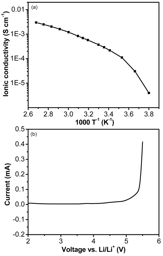
PEO-based SPEs generally exhibit low ionic conductivity from 10-8 to 10-5 S cm-1 at room temperature [9-11]. Therefore, one of the most important parameters dominating LIBs is to enhance the ionic conductivity. The temperature dependence of the ionic conductivity of the SPE at temperature range from -10 to 100°C is shown in Fig. 1a. The result shows that the semi-IPN PEO-based SPE had high ionic conductivity of about 2.9 × 10⁻⁴ S cm-1 at room temperature. In addition, the electrochemical stability of the SPE is also a crucial property for high charging voltage of LCO-based LIBs. The electrochemical stability was examined by LSV using a stainless-steel/SPE/Li metal coin cell with a sweep rate of 0.5 mV s-1 from 2 to 5.5 V (vs. Li/Li+). As shown in Fig. 1b, the SPE started to degrade at 5 V (vs. Li/Li+), indicating the SPE can be stable up to 5 V. The values of ionic conductivity and electrochemical stability are higher than that of the previous reports [14,20], meaning that the prepared semi-IPN SPE was stable enough to apply for most LIBs at high voltage.
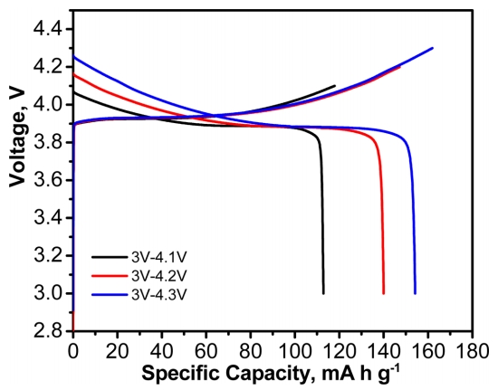
Knowing the semi-IPN PEO-based SPE had high ionic conductivity and electrochemical stability window, LCO is used for cathode materials using prepared SPE. The charge-discharge characteristics of LCO/SPE/Li metal cells at different cut-off voltages were investigated. As shown in Fig. 2, the discharge capacity at 0.1 C was about 113, 140, and 154 mA h g-1 with cut-off voltages from 3 to 4.1, 4.2, and 4.3 V, respectively. These values are similar to the discharge capacities of liquid electrolytes [21]. This result demonstrates that the PEO-based SPE is suitable for room-temperature-operated LCO/SPE/Li metal cells without significant loss of capacity.
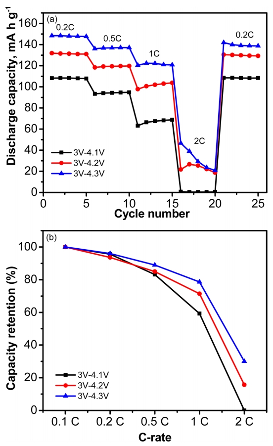
For practical application in lithium polymer batteries, we examined the rate capability performance from 0.2 to 2 C at different cut-off voltages. The charge-discharge profiles of LCO/SPE/Li metal cells are exhibited in Fig. 3 and Fig. S1. As shown in Fig. 3a, the cell in the voltage range of 3.0 - 4.3 V delivers a discharge capacity of 148 mA h g-1, 137 mA h g-1, 121 mA h g-1, and 46 mA h g-1 at 0.2 C, 0.5 C, 1C, and 2 C, respectively. For comparison, the cell with a voltage range of 3.0 - 4.2 V has a discharge capacity of 131 mA h g-1, 119 mA h g-1, 100 mA h g-1, and 22 mA h g-1 at 0.2 C, 0.5 C, 1C, and 2 C, respectively. And the cell voltage between 3.0 and 4.1 V has a discharge capacity of 108 mA h g-1 at 0.2 C, 94 mA h g-1 at 0.5 C, 67 mA h g-1 at 1 C, and 0 mA h g-1 at 2 C. Fig. 3b exhibit the capacity retention values at various discharge rates. The cell with a voltage range of 3.0 - 4.3 V has the highest rate performance compared with cells having other cut-off voltages because the higher the charging voltage that is applied, the more capacity that can be delivered. The semi-IPN PEO-based SPE showed outstanding rate performance of LCO-based LIB at room temperature up to 4.3 V, which can be attributed to the high ionic transport capability as well as decreasing electrode/electrolyte interfacial resistance by means of in-situ cross-linking reaction [13,15].
With the cells having a high rate performance, we continued investigating the dependence of cell cycle performance on different voltage ranges. Fig. 4a shows the cycling performance of LCO/SPE/Li metal cells using a bare Al current collector with different cut-off voltages at a current density 0.5 C. The cell with cut-off voltages from 3 to 4.3 V has an initial discharge capacity about 133 mA h g-1. The discharge capacity gradually decreases during cycling and then it becomes unstable after 27 cycles. For comparison, the cell with a cut-off voltage from 3 to 4.2 V has an initial discharge capacity about 118 mA h g-1 and begins to be unstable after 60 cycles. On the other hand, the initial discharge capacity of the cell with voltage range between 3.0 and 4.1 V is about 94 mA h g-1, and it is stable up to 90 cycles then the capacity starts to decrease. Even though they had a high initial discharge capacity, the poor cyclability of the cells in the voltage range of 3.0 - 4.3 V and of 3.0 - 4.2 V can be attributed to the Al corrosion resulting from the formation of Al(TFSI)3 at high voltage [22-24]. Therefore, to further improve the cycle life of cells at high voltage, one of the most important issues is to suppress the Al corrosion during cycling.
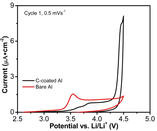
It is known that carbon coating of Al foils can protect the Al from corrosion at high cut-off voltages [25-27]. Therefore, we applied carbon-coated Al (C-coated Al) as a current collector for the PEO-based SPE and investigated the cycling performance of the cells. Fig. 4b shows the cyclability of the LCO/SPE/Li cells using C-coated and bare Al current collectors between 3 and 4.2 V with a charge-discharge rate of 0.5 C. It can be seen that the cell with C-coated Al has an initial discharge capacity about 122 mA h g-1 with higher stability up to 70 cycles compared with the cell using bare Al. The Al corrosion was investigated by means of a CV using Al/SPE/Li metallic half-cells with bare Al and C-coated Al at a voltage range from OCV to 4.5 V (vs. Li/Li+) and under a scan rate of 0.5 mV s-1. As shown in Fig. 5 that the current density increased rapidly at about 3.3 V (vs. Li/Li+) and the current peak was seen at about 3.6 V (vs. Li/Li+) for the bare Al. This current variation may be attributed to the corrosion of Al [28]. On the other hand, this peak was not seen with the C-coated Al sample. However, the current response of the C-coated Al sample quickly increased at 4.25 V (vs. Li/Li+) compared with bare Al sample. These results indicate that although using C-coated Al can significantly suppress the Al corrosion in the cells, it actually accelerates the electrolyte oxidation reaction [29], resulting in the stability of the cell only reaching 70 cycles.
Finally, to further examine the effect of high voltage range on the performance of LCO-based lithium polymer batteries, electrochemical impedance spectroscopy of the LCO/SPE/Li cells using C-coated and bare Al current collectors was investigated. Battery impedance comprises the bulk resistance (Rbulk) related to the ionic conductivity and the interfacial resistance (Rintf) that includes solid electrolyte interface resistance (Rf) and the charge transfer resistance (Rct) [30]. At the high frequency, the intercept with the real axis is Rbulk and the distorted semicircle exhibits Rintf [31]. Fig. 6 shows the Nyquist plots of a LCO/SPE/Li metal cell using C-coated and bare Al after 1, 20, 40, and 60 cycles with voltage ranges between 3 and 4.2 V. For both samples, Rbulk remained constant during cycling, indicating that the ionic conductivity of SPE was very stable. In addition, the Rintf reduced significantly from the 1st cycle to the 20th cycle, which can be attributed for the stable formation of electrode/electrolyte interface resistance, leading the Rct was decreased. From the 20th cycle to 60th cycle, the Rintf value of the C-coated Al sample remained the same value, but the Rintf of the bare Al sample increased and had a higher value compared with that of the C-coated Al sample. This phenomenon indicates again that C-coated Al can suppress Al corrosion in the cell, leading to stable resistance of the cell. In contrast, the cell with bare Al suffered Al corrosion during cycling, leading to increased resistance of the cell.
4. Conclusions
In conclusion, a semi IPN PEO-based SPE was prepared by thermally cross-linked reaction. The SPE had high electrochemical stability window up to 5 V and it could be applied to a 4 V class cathode material of LCO at room temperature. The LCO/SPE/Li metal cell showed good electrochemical rate performance at a high cut-off voltage up to 4.3 V due to high ionic transport capability as well as decreasing electrode/electrolyte interfacial resistance. However, the cycle life of the SPE-based cells was very poor because of Al corrosion process during cycling. By using the C-coated Al current collector, the Al corrosion was suppressed, leading to improved cycling performance of the cell.