1. Introduction
After a long development period, a molten carbonate fuel cell (MCFC) has reached the commercial stage in the US and Korea. It could potentially be used for a large proportion of the world’s fuel cells, but to increase its utilization, a longer life and a more economic fuel must be developed. Natural gas is a common fuel for MCFCs, but it is a high price fuel.
To overcome the fuel cost problem, direct use of carbon for the fuel cell has been attempted. Since carbon is a conductive material, it is considered as an electrode as well as a fuel. To oxidise solid carbon the fuel cell generally requires a high temperature of over 700 ℃. A recent report has suggested that carbon is gasified to CO with molten carbonate, and then the CO is oxidised to CO
2 [1]. A 100 cm
2 class MCFC was used for direct carbon fuel, and it was concluded that carbon oxidation had occurred via CO
[2].
Another possible fuel is AFC. It can be prepared by two methods; one is a solvent extraction of organic components from coal followed by separation of solvent and organic materials. The other is dissolution of ash components by acids or bases. AFC has a very low ash content and relatively low gasification temperature compared with carbon. Since AFC has no electric conductivity, it only works as a fuel by gasification to H
2 and CO. Most AFC oxidation was carried out in a DCFC (direct carbon fuel cell) based on SOFC (solid oxide fuel cell) technology
[3,
4]. To date, no report is available for a DCFC run by AFC based on MCFC technology.
Hydrogen oxidation in molten carbonates is shown in Eq. (1):
However, the oxidation reaction comprises several reaction steps
[5]:
H2 + 2M = 2MH
MH + OH− = H2O + M + e−
Due to these reaction steps, the reaction rate has the following relationship for H
2, CO
2 and H
2O (Eq. 2)
[5]:
The relationship shown in Eq. 2 indicates that the H2O and CO2 species participate in the oxidation with positive reaction orders. In general, it is considered CO2 is supplied to the anode to prevent carbonate decomposition (Eq. 3).
Moreover, H2O is also fed to reduce carbon deposition by the water-gas shift reaction (Eq. 4).
Besides the reasons indicated by Eq. 3 and 4, Eq. 2 explains that CO
2 and H
2O are necessary components for H
2 oxidation. Therefore, the much smaller amounts of them than H2 in conventional hydrogen fuel gives rise to a significant overpotential due to the CO
2 and H
2O species
[6].
In this work, the oxidation behaviours of AFC and carbon were investigated by comparison with hydrogen fuel in a coin type MCFC. The overpotential was analysed in terms of gas composition with a gas chromatograph (GC) and current densities with the electrochemical analysis methods of steady state polarisation, step chronopotentiometry (SC) and electrochemical impedance spectroscopy (EIS).
2. Experimental Section
A coin type MCFC was built with electrodes ca. 4 cm in diameter. The anode was a porous Ni alloy, and the cathode was porous in-situ oxidised NiO. The matrix was made of LiAlO
2 powder and the electrolyte was a Li
2CO
3-K
2CO
3 eutectic. The coin cell was installed in a furnace and the anode had a long alumina tube of 3 cm I.D. to introduce the coal fuel. More details were described in a previous work
[1].
The AFC was prepared from a bituminous Indonesian Berau coal. It was extracted with a microwave at 202 ℃ with an organic solvent of NMP (N-methyl-2-pyrrolidinone)
[7]. The carbon was home-made from oak at 400 ℃ in a N
2 environment. The AFC or carbon was used to fill a small alumina tube of O.D. 1.5 cm, and then it was supplied to the anode chamber. Specifically, 3 g of carbon was supplied to the fuel cell as a eutectic mixture with 3 g of 38 mol% Li
2CO
3 and 62 mol% K
2CO
3. Prior to the introduction of AFC or carbon, the cell was operated with a normal H
2 fuel (0.125 L min
−1 H
2 + 0.025 L min
−1 CO
2 + 14 % H
2O) and a cathode gas (0.150 L min
−1 air + 0.100 L min
−1 CO
2). The H
2 fuel was used to check the cell performance. When the AFC or carbon was introduced, the H
2 fuel was stopped while the cathode gas was kept constant. To prevent O
2 diffusion into the anode, the anode chamber was maintained at a higher pressure than outside by flowing N
2 into the anode. More detailed preparation and operation procedures were described in a previous work
[1,
7].
Gas composition from the AFC was measured with a GC (Model HP G1530A). The AFC and carbonate mixture (3 g AFC and 3 g Li-K carbonates) were placed in a closed alumina tube, which was heated to 850 ℃. To measure the gas generation rate, nitrogen at 0.1 L min−1 was flowed into the tube. Then the outlet gas compositions were measured with the GC and gas generation rates were obtained by comparison with the nitrogen composition.
Electrochemical methods of steady state polarisation, SC, and EIS were employed. The steady state polarisation was carried out with a potentiostat (PAR 2273) in the current range up to 150 mA cm−2. The SC showed voltage relaxations by 50 mA cm−2 steps in the current for 60 s up to 150 mA cm−2. There were therefore three steps in the SC measurement. The EIS was measured in an open circuit state by applying 5 mV rms in the frequency range from 1 kHz to 0.01 Hz.
3. Results and Discussion
Fig. 1 compares current-voltage behaviours of AFC+N
2 fuel (AFC 3 g + N
2 0.1 L min
−1), AFC+CO
2 fuel (AFC 3 g + CO
2 0.025 L min
−1), and H
2 fuel (H
2 0.125 L min
−1 + CO
2 0.025 L min
−1 + 14 % H
2O) at 850 ℃. The equilibrium constant (
Keq) of the water-gas shift reaction (Eq. 5) is about 0.91 at 850 ℃. The value was obtained by the interpolation of Gibbs energy of the reaction (5) between 1100 and 1200 K
[8].
Fig. 1.
Current-voltage behaviours of 3 g AFC + 0.1 L min−1 N2 (AFC+N2), 3 g AFC + 0.025 L min−1 CO2 (AFC+CO2), and 0.125 L min−1 H2 + 0.025 L min−1 CO2 + 14 % H2O (H2+CO2+H2O) fuels at 850 ℃.

Thus, the calculated open circuit voltage (EOCV) of the H2 fuel at 850 ℃ is 1.053 V according to Eq. 6.

The measured
EOCV of the H
2 fuel of 1.052 V is very close to the theoretical one. On the other hand, the
EOCVs of the AFC fuels are 1.300 V for AFC+N
2 and 0.885 V for AFC+CO
2 fuel. Since the
EOCV is determined by temperature and gas composition as shown in Eq. 6, the
EOCVs for AFC represent a deviation of gas compositions from the H
2 fuel. In particular, the high
EOCV of 1.300 V for AFC+N
2 was due to the very small amounts of CO
2 and H
2O at the anode because the AFC was fed in a dry state. The addition of CO
2 to the AFC+CO
2 fuel raised the CO
2 partial pressure, and the lowest
EOCV of 0.885 V was obtained. The H
2 fuel shows clear linearity by applying current, which indicates that the MCFC reactions are mass transfer control processes
[9]. The mildest slope was also observed for the H
2 fuel, representing the lowest mass transfer resistance among the fuels. The steepest slope is obtained for AFC+N
2 fuel although it has the highest
EOCV. It means the AFC+N
2 fuel has the largest mass transfer resistance among them. An interesting point is that the AFC+N
2 fuel had milder slopes at higher current densities. This indicates that the resistance had been changed by the current and less resistance existed at higher currents. However, the AFC+CO
2 fuel had a consistent slope much milder than that of AFC+N
2.
Fig. 2 shows gas generation rates for AFC. H
2 and CO are the main gases from AFC, and CO
2 and CH
4 are the minor components. Those gases are mostly generated for 30 min, however the cell continued for several hours with 3 g of AFC. Since the current density of 150 mA cm
−2 is 1.05 A, which corresponds to ca. 7.3 mL min
−1 of H
2, thus the cell could be operated for several hours. H
2O could not be detected by the GC, but the amount must be very small because the AFC was kept dry and the H
2O composition in the AFC was about 2 wt%
[7]. Identical gas generation behaviour for AFC has also been reported
[3]. Therefore it is clear that the large mass transfer resistance of the AFC+N
2 fuel shown in
Fig. 1 was due to the low amounts of CO
2 and H
2O. Although the steady state polarisation in
Fig. 1 was measured within 30 min of the AFC being supplied, the steep decrease of gas generation rates resulted in a large mass transfer resistance, especially due to CO
2 species. Consequently, the CO
2-added fuel of AFC+CO
2 had much less resistance than AFC+N
2 fuel because the added CO
2 raised its partial pressure and reduced resistance according to Eq. 2.
Fig. 2.
Gas generation rates of various gases from AFC at 850 ℃.

Fig. 3 compares SC results for the three fuels −H
2 fuel, AFC+N
2, and AFC+CO
2 - at 850 ℃. The SC method reveals reaction characteristics by voltage relaxation. The H
2 fuel showed consistent and very fast voltage relaxations at the three current steps, showing that H
2 oxidation is very fast with a low mass transfer resistance. However, AFC+N
2 fuel had a very large and very slow voltage relaxation for the first current step up to 50 mA cm
−2, indicating that AFC oxidation is very slow with a large mass transfer resistance. A possible reason for this large resistance is due to the lack of CO
2 and H
2O species in the reactant gases because AFC generates very small amounts of CO
2 as seen in
Fig. 2, and H
2O as mentioned above. In particular, the voltage relaxations of the AFC+N
2 fuel become faster and smaller at higher current densities. This can be explained by the production of H
2O and CO
2 in the reaction at the anode as shown in Eq. 1. A higher current density generates more H
2O and CO
2 at the anode, which reduces mass transfer resistances of the species. The effect of CO
2 at the anode is confirmed by the AFC+CO
2 fuel, which shows much smaller and faster voltage relaxations at the current steps than those of the AFC+N
2 fuel. Consequently, the addition of CO
2 reduces its mass transfer resistance, although
EOCV is decreased according to Eq. 6.
Fig. 3.
Step chronopotentiometric results of 3 g AFC + 0.1 L min−1 N2 (AFC+N2), 3 g AFC + 0.025 L min−1 CO2 (AFC+CO2), and 0.125 L min−1 H2 + 0.025 L min−1 CO2 + 14 % H2O (H2+CO2+H2O) fuels at 850 ℃.

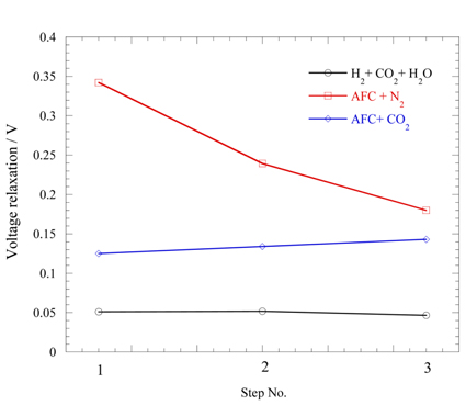
Fig. 4 shows the voltage relaxation values for each of the current steps for the three fuels. They were measured by voltage relaxation for 60 s. Steps 1, 2, and 3 mean the current steps from 0 to 50 mA cm
−2, 50 to 100 mA cm
−2, and 100 to 150 mA cm
−2, respectively. The H
2 fuel has the lowest values for the steps, indicating it has a very low overvoltage. The AFC+N
2 fuel shows a decrease in the values with increasing current. As mentioned before, the product species of H
2O and CO
2 reduce the mass transfer resistance, so that the relaxation values decrease. The AFC+CO
2 fuel shows much lower and more stable values than AFC+N
2. It shows that the addition of CO
2 to AFC significantly reduces the mass transfer resistance of the species. Much larger voltage relaxations for AFC+CO
2 than those for the H
2 fuel would be due to the insufficient gas generation from AFC, thus a larger mass transfer resistance exists for the AFC+CO
2 fuel.
Fig. 4.
The relaxed voltages for 60 s at every current step of Fig. 3. Step 1 is that at the current step from 0 to 50 mA cm−2, step 2 to 100 mA cm−2, and step 3 to 150 mA cm−2.

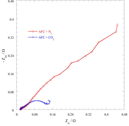
Fig. 5 shows the EIS results for the two fuels AFC+N
2 and AFC+CO
2 at 850 ℃. Since the real values at the highest frequency are the same in both fuels, the cell has identical internal resistance for both fuels. In particular, the AFC+N
2 fuel shows very large impedance in the low frequency region. This shows that a very large mass transfer resistance exists for the fuel. The reason is the very small amount of H
2O and CO
2 species at the anode compared with the H
2 fuel. This can be confirmed by addition of CO
2 to AFC. The CO
2-added fuel of AFC+CO
2 gives very small impedance compared with AFC+N
2 because the addition of CO
2 reduces the resistance.
Fig. 5.
Electrochemical impedance spectroscopy results of 3 g AFC + 0.1 L min−1 N2 (AFC+N2) and 3 g AFC + 0.025 L min−1 CO2 (AFC+CO2) fuels at 850 ℃, open circuit voltage state.

The CO
2 addition effect was also attempted for carbon fuel.
Fig. 6 shows the SC results for carbon and 0.1 L min
−1 of N
2 (C+N
2), carbon and 0.025 L min
−1 of CO
2 (C+CO
2), and H
2 (H
2 0.125 L min
−1 + CO
2 0.025 L min
−1 + 14% H
2O) fuels at 850 ℃. Carbon is also a solid fuel, so that its direct oxidation to CO
2 would be difficult
[1]. In general, it is accepted that carbon oxidation in a fuel cell proceeds via carbon monoxide
[1,
10]. The carbon is gasified with molten carbonates over 700 ℃ and CO is the main species
[11]. Therefore, 3 g of carbon and 3 g of carbonates were mixed and supplied to the anode as a carbon fuel in this work. Since the C+N
2 fuel has a very small CO
2 and H
2O content, the mass transfer from them would be significant. Therefore, much larger voltage decreases are observed for C+N
2 compared with the H
2 fuel. However, faster and smaller voltage relaxation is also observed at the higher current density steps. This behaviour is very similar to that of AFC, showing they have similar oxidation paths, and a deficiency of CO
2 produces a large mass transfer resistance. On the other hand, the CO
2-added fuel (C+CO
2) shows very stable voltage relaxations, although the
EOCV is decreased for the same reason as for AFC+CO
2. The consistent voltage relaxations for the C+CO
2 fuel indicate that the added CO
2 sufficiently reduced the resistance.
Fig. 6.
Step chronopotentiometric results of 3 g C + 0.1 L min−1 N2 (C+N2), 3 g C + 0.025 L min−1 CO2 (C+CO2), and 0.125 L min−1 H2 + 0.025 L min−1 CO2 + 14 % H2O (H2+CO2+H2O) fuels at 850 ℃.

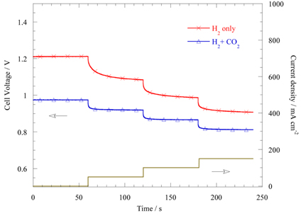
Fig. 7 shows the SC results for H
2 only and H
2+CO
2 fuels at 850 ℃. When the anode was supplied only with H
2, smaller and faster voltage relaxation was observed at higher current densities. This is very similar to the AFC+N
2 fuel due to a larger mass transfer resistance with a smaller amount of CO
2. Therefore, deficiency of CO
2 species at the anode results in significant mass transfer resistance regardless of fuel species. The CO
2-added fuel of H
2+CO
2 shows a much faster and smaller voltage relaxation than H
2 only fuel, although CO
2 addition decreases the
EOCV.
Fig. 7.
Step chronopotentiometric results of 0.125 L min−1 H2 (H2 only) and 0.125 L min−1 H2 + 0.025 L min−1 CO2 + 14 % H2O (H2+CO2+H2O) fuels at 850 ℃.


