1. Introduction
Electrochemical CO2 reduction reaction (CO2RR) and hydrogen evolution reaction (HER) are recognized as promising strategies for storing renewable energy as chemical feedstock [1,2]. However, practical applications of CO2RR and water electrolysis have suffered from the anodic oxygen evolution reaction (OER) [3–5], which requires a high overpotential because of the kinetically slow four-coupled electron and proton transfer pathways. Several OER electrocatalysts have been developed to reduce the overpotential. In particular, precious-metal-based Ir or Ru catalysts are predominantly used at present [6]. Therefore, inexpensive electrocatalysts with high activity are extensively studied to realize economically feasible energy-conversion electrolysis.
Recently, transition-metal-based OER catalysts such as metal oxides, metal sulfides, and layered double hydroxides have been reported [7–9]. Among these, naturally abundant Ni catalysts have received considerable attention [10,11]. However, Ni catalysts generally undergo changes concerning the charge state and atomic structure during electrocatalysis [12,13]; therefore, correlating the catalytic activities with their structures is challenging. In addition, cutting-edge Ni-based OER catalysts typically require thermal treatment, significantly increasing the cost of production [14–16].
Recently, atomically precise metal nanoclusters (NCs) have been studied in various electrochemical systems [17–23]. They can be isolated as single species with molecular purity and show well-defined structures, as confirmed by X-ray crystallography [24]. Among them, Ni NCs are typically synthesized in the formula Nin(SR)2n, where SR is a thiolate ligand (abbreviated as Nin) [25–27]. The Ni NCs are stable because of ligand protection and delocalized electrons on the cyclic ring structure [28,29]. In previous studies, Ni NCs have been exploited as OER electrocatalysts, typically immobilized on carbon substrates [30–33]. Kauffman et al. reported that Ni6 NC exhibits higher activity than Ir or NiO. Using density functional theory calculations, they ascribed the high OER activity of the Ni6 NC to the enhanced kinetics in the first electron transfer step [30]. Hussain et al. also reported the OER activities of Ni4 and Ni6 NCs, which exhibited higher OER activities than typical Ni-based electrodes [31]. Recently, Jin et al. reported the size-dependent OER activities of Ni4, Ni5, and Ni6 NCs [32].
Although Ni NCs have been extensively studied as efficient electrocatalysts for water oxidation, their OER activity is far below the commercially viable level. Although carbon supports offer high electronic conductivity, they are prone to corrosion under electrochemical oxidation [34,35]. Although graphitized carbon species show relatively slow corrosion rates compared with typical carbon black [36], they also gradually corrode at high anodic potentials during long-term operations. Therefore, carbon-free OER catalysts with high durability are in high demand.
This study reports the preparation and OER activity of Ni-foam (NF)-supported Ni6 NCs (Ni6/NF) fabricated using the dip-coating method. The Ni6 NC exhibited extraordinary OER activity on an NF substrate in an alkaline electrolyte. It showed high OER activity with a current density ( j) of 500 mA/cm2 at a low overpotential (η) of 0.39 V, outperforming the commercial IrO2 electrocatalysts. Electrokinetic studies revealed that the high OER activity of Ni6/NF originates from facile electron transfer on the non-corrosive substrate. In this study, an NC-based zerogap CO2 electrolyzer was constructed using a Au25-immobilized gas diffusion electrode (Au25/GDE) and Ni6/NF electrodes as the cathode and anode, respectively, which exhibited highly active and stable CO2RR and OER operations.
2. Experimental
2.1 NC Synthesis
The Ni6(SEtPh)12 NCs were synthesized following a previously reported method [37]. Briefly, NiCl2·6H2O (Merck, reagent grade, 0.42 mmol) and tetraoctylammonium bromide (Merck, 98%, 0.89 mmol) were dissolved in tetrahydrofuran (100 mL). After stirring for 30 min, 2-phenylethanethiol (HSEtPh) (Merck, 98%, 2.17 mmol) was added. NaBH4 (Merck, 99%, 4.23 mmol) dissolved in cold water (14 mL) was added after 5 min, and the solution was stirred for an additional 24 h. The product was evaporated using a rotary evaporator. The organic phase was then separated and washed several times with methanol. The product was extracted using dichloromethane (CH2-Cl2) and crystallized by layering ethanol (10 mL) over the NC solution in CH2Cl2 (10 mL).
Au25(SC6H13)18 NC was prepared according to the previously reported procedure [38].
2.2 Characterizations of NCs
Ultraviolet-visible (UV-vis) absorption spectra of the NCs in CH2Cl2 were obtained using a Shimadzu UV-vis-NIR spectrophotometer (UV-3600). Electrospray ionization (ESI) mass spectra were acquired using the negative ion mode in an ESI mass spectrometer (Agilent 6230 TOF LC/MS).
Single-crystal X-ray diffraction (SC-XRD) analysis was conducted on the crystals of Ni6(SEtPh)12 NCs grown at 25°C by layering hexanes over CH2-Cl2 solution of Ni6(SEtPh)12 NCs (Fig. S1). The PAL BL2DSMDC program [39] was used for data collection. Cell refinement, reduction, and absorption correction were performed using HKL3000sm (Version 716.7) [40]. The crystal structure of Ni6(SEtPh)12 NCs was solved using the direct method with SHELX-XT (Ver. 2014/5) [41] and refined by full-matrix least-squares calculations with the SHELXXL (Ver. 2016/4) [42] in the Olex2 [43] program package. The diffused electrons in large solvent-accessible void were treated using the SQUEEZE procedure (PLATON) [44,45].
After electrolysis experiments, the Ni6 NCs and Nafion were extracted from the Ni6/NF electrode using a mixture of CH2Cl2 and methanol. Pure Ni6 NCs were further extracted with CH2Cl2 with approximately 50% of the recovery. The recovered NCs were analyzed using UV-vis absorption spectroscopy and mass spectrometry (Bruker, Autoflex Max).
2.3 Preparation and Characterization of Electrodes
The Ni6 suspension for the 1 cm2-electrode was prepared by mixing Ni6 NC (1.0 mg) and Nafion (10 μL) (5 wt.%, Merck) in methanol (1.0 mL) and sonicating for 10 min. For large-scale fabrication, the suspension was scaled up proportionally to the electrode area. The Ni6/NFs were prepared by dipping the NF (29-04275-01, Invisible Inc.) in the prepared suspension for 5 s and drying it for 1 h under a dynamic vacuum. We determined the loading amount of Ni6 NC on the NF by measuring the weight change of the NF after the dipping process. Typical NC loading was determined to be 0.089±0.008 mg/cm2. In addition, the loading amount was controllable (0.02, 0.05, and 0.1 mg/cm2) by changing the Ni6 concentration (0.2–1.0 mg/mL) in the dipping solution. Scanning electron microscopy (SEM), and energy-dispersive X-ray spectroscopy (EDS) analyses of the Ni6/NF electrodes were performed using a JEOL scanning electron microscope (JEOL-7800F). For the EDS analysis of sulfur of the Ni6/NF electrodes, the same weight of polyvinylidene fluoride (PVDF) binder was used instead of the sulfur-containing Nafion. The Ni6-immobilized GDE (W1S1011, Ce-Tech) (Ni6/GDE) was fabricated by spreading Ni6 NC solution (0.5 mg of Ni6 NC in 0.16 mL of acetone and 0.16 mL of CH2Cl2) on the microporous layer of 1 cm2-GDE. To compare the OER activities, commercial IrO2-coated GDEs (IrO2/GDEs) were purchased from Dioxide Materials.
The Au25/GDE was prepared according to the procedure reported in a previous study [19].
2.4 Electrochemical Measurements
The half-cell measurement of the electrochemical OER was conducted using a three-electrode system in a one-compartment cell containing 20 mL of 1.0 M KOH solution with vigorous stirring to remove the generated O2 bubbles and promote mass transport. The prepared anodes were used as the working electrodes; the typical anode area was 1 cm2. A Pt foil cathode (1 cm2) and Ag/AgCl (1.0 M KCl) were employed as the counter and reference electrodes, respectively.
Linear sweep voltammetry (LSV), chronopotentiometry (CP), and electrochemical impedance spectroscopy (EIS) measurements were performed using a potentiostat (ZIVE BP2, WonATech). The NF anodes were pre-activated by conducting CP at 100 mA for 2 h before measuring their OER activity. LSV was conducted at a scan rate of 20 mV/s. The impedance spectra were recorded in a potentiostatic mode at various applied potentials in the frequency range of 100 kHz to 0.01 Hz with an amplitude of 10.0 mV.
The anode potentials recorded on the Ag/AgCl scale (EAg/AgCl) were converted to the reversible hydrogen electrode (RHE) scale (ERHE) and η using the following equations:
The potential (E) was iR-compensated.
To measure the Faradaic efficiency of O2 (FEO2), a laboratory-made, gas-tightened H-cell was used [20]. Residual air was purged with Ar gas, and the cell was tightly sealed. CP was performed at 50 mA for 1 h. After electrolysis, the headspace of the anode was analyzed by gas chromatography (GC) (GC 7890B, Agilent) equipped with a thermal conductivity detector and a flame ionization detector.
The full-cell measurement for CO2RR-OER co-electrolysis was conducted in a zero-gap CO2 electrolyzer [46], and the active areas of the cathode and anode were confined to 5 cm2 by a flow field. CO2 gas (200 sccm, humidified at 25°C) was fed into the cathode flow field, and fresh 1.0 M KOH was supplied to the anode line. In all CO2RR experiments, CO and H2 were produced as cathodic reaction products.
3. Results and Discussion
Ni6(SEtPh)12 NC was prepared according to a previously report (see the Experimental section for details) [37]. The Ni6 NC was synthesized as a single species (Fig. 1a) with a yield of ~50% based on Ni. The SC-XRD analysis clearly revealed the atomic structure of the Ni6(SEtPh)12 NC, which is composed of six hexagonally arranged Ni atoms and twelve thiolate ligands located at intervals of the Ni ring (Fig. 1b). The atomic structure is consistent with that reported previously [37]. The Ni6 NC showed exceptional stability owing to its protecting ligands and electron delocalization following the ring structure [28,29].
The synthesized Ni6 NCs were further characterized using ESI mass spectrometry and UV-vis absorption spectroscopy. The single peak in the ESI mass spectrum (Fig. 1c) indicates that the obtained NC exists with molecular purity. The peak observed at m/z of 2034 Da was assigned to the NC-chloride adduct of [Ni6(SEtPh)12]Cl− formed during ionization, by matching the simulated isotope pattern (Fig. 1c, inset). The UV-vis absorption spectrum of the Ni6 NC (Fig. 1d) exhibits four characteristic absorption peaks at 339, 410, and 535 nm, indicating that the Ni6 NC has a discrete energy level.
The Ni6 NCs are very small (ca. 1.6 nm in diameter, including the ligand chain) and stable; therefore, they can be directly immobilized on NF electrodes even without support such as carbon black. The dip-coating process is considered an easily processable catalyst coating method [47,48]. Ni6/NF was prepared by simply dipping the NF into a Ni6 dipping solution (Fig. 2a). Methanol, in which the Ni6 NC is poorly soluble, was chosen as the suspension medium to make Ni6 NC weakly interact with the solvent and thereby anchor on NF. The use of a binder, either PVDF or Nafion, assisted the dispersion of the Ni6 NCs (Fig. S2), resulting in a uniform suspension. Despite short dipping time, the loading amount was found to be consistent in the reproducible test (Fig. S3).
To confirm the distribution of Ni6 NCs on the NF, we performed the SEM and corresponding EDS of the Ni6/NF. The existence of the Ni6 NC can be tracked by the sulfur atoms of the thiolate ligands in the EDS elemental mapping image. Therefore, we used PVDF as a binder instead of Nafion for the SEM-EDS measurements to avoid interference from sulfur of Nafion. SEM images show some aggregates of Ni6 NCs on the NF substrate (Figs. 2b and S4a). However, the SEM-EDS elemental mapping images of Ni6/NF show that the Ni6 NCs were uniformly distributed throughout the NF, as monitored by the sulfur atoms (Figs. 2b and S5).
The OER activity of Ni6/NF was measured by LSV in a 1.0 M KOH electrolyte solution. Before measuring the OER activity, the electrodes were pretreated by conducting CP at an anodic current of 100 mA/cm2 for 2 h. A significant increase in the oxidative current was observed after CP (Fig. S6a), suggesting that Ni6/NF underwent some kind of activation process during CP. After CP electrolysis, Ni6/NF displayed a clean surface without NC aggregates (Fig. S4b). Extracting NCs from Ni6/NF after electrolysis, the electrode exhibited OER activity similar to that of bare NF (Fig. S6b), and the retrieved NCs showed nearly identical profiles to the intact NCs (Fig. S7). These results suggest that the activation can be attributed to the uniform spreading of Ni6 NCs on the NF substrate during CP electrolysis.
As shown in Fig. 2c, Ni6/NF showed a higher OER activity than bare NF. The OER current on Ni6/NF started from an η of 0.30 V and reached 500 mA/cm2 at a low η of 0.39 V. The OER activity of Ni6/NF was slightly higher with the Nafion binder than with the PVDF binder because of the enhanced ion conductivity of the electrode [49]. Thus, OER experiments were conducted on Ni6/NF with a Nafion binder. The OER activity of Ni6/NF increased with increasing Ni6 loading (Fig. S8a), showing the highest activity at a loading of 0.1 mg/cm2. Both η values for achieving 10 and 100 mA/cm2 were decreased as increasing the loading amount (Fig. S8b).
The high processability of the dipping method enables large-scale preparation of Ni6/NF. Fig. 2d shows the OER activity of various sized Ni6/NF. Evidently, the total oxidative current increases with increasing electrode area. The dip-processed 9 cm2 of Ni6/NF shows an OER current of 2.0 A at an η of 0.38 V. Normalized to the area, the j-E profile of the electrodes was nearly identical (Fig. 2d, inset), indicating that the unit activity is similar for different-sized electrodes. This suggests that large-area Ni6/NF electrodes can be readily fabricated by scaling up the dipping process.
Though Ni NCs have been exploited as OER electrocatalysts in previous reports [30–32], they were supported by carbon substrates. However, carbonaceous materials easily corrode under electro-oxidation conditions [34]. Therefore, Ni6/NF is a promising electrode for sustainable OER. To compare the effect of the carbon substrate, a carbon-based GDE was used as the substrate for the Ni6 and IrO2 catalysts. IrO2/GDE exhibited a lower η (0.27 V) for the onset of the catalytic current than Ni6/NF; however, its OER activity was lower than that of Ni6/NF over 100 mA/cm2 (Fig. 3a). Surprisingly, Ni6/GDE showed extremely low catalytic activity compared to Ni6/NF and IrO2/GDE (Fig. 3a). The OER activity obtained for Ni6/GDE was in a similar range to those obtained in other studies [30–33].
To investigate the origin of the difference in OER activities, we quantitatively measured the FEO2 on the electrodes (Fig. 3b) using GC analysis. IrO2/GDE produced a FEO2 of 98% despite using a carbon substrate. This is attributed to the high loading (4.8 mg) of the IrO2 catalyst, which can prevent the electrooxidation of GDE. However, the FEO2 measured for Ni6/GDE was significantly low (82%), indicating that the GDE was actively corroded during electrochemical OER (Fig. S9). In contrast, Ni6/NF only performs OER with FEO2 of 100%, indicating that all the produced electrons originate from water oxidation without any side reactions. This result suggests that corrosion-free electrodes can lead to highly active OER activities.
To further investigate the origin of the high OER activity of Ni6/NF, electrokinetic studies were performed. First, Tafel analysis was performed by plotting log j vs. η in the kinetically controlled region. In Fig. 3c, IrO2/GDE shows a Tafel slope of 79 mV/dec, which is consistent with the reported values [50–52]. The Tafel slope obtained for Ni6/GDE is high (130 mV/dec) owing to carbon degradation. In contrast, the slope of Ni6/NF was very low at 41 mV/dec, indicating that Ni6/NF can initiate the OER with fast kinetics. In particular, the OER in a neutral-alkaline solution involves four concerted proton-electron transfers described by the following elementary steps (here, * indicates the active site) [53]:
The theoretical Tafel slopes were 120 and 40 mV/dec when steps (3) and (4) were the rate-determining steps (RDSs), respectively [54]. Thus, the low Tafel slope of ~40 mV/dec observed for Ni6 NC suggests that step (4) is the RDS of the OER on the Ni6/NF electrode. This implies that the first hydroxide adsorption is facilitated on the Ni6/NF with fast electron transfer. This result is in good agreement with previously reported theoretical predictions for the OER on Ni6 NC [30].
EIS was performed to compare the electron transfer kinetics of the electrodes. Fig. 3d shows the Nyquist plots obtained on IrO2/GDE, Ni6/GDE, and Ni6/NF at 1.64 V in 1.0 M KOH. IrO2/GDE shows two semicircles; the small semicircle in the high-frequency region represents the internal charge transfer of the electrode (Rct-int), and the second semicircle in the low-frequency region is accompanied by external charge transfer between the electrode and reactants (Rct-ex) [55]. Rct-int was absent on the Ni6/GDE and Ni6/NF electrodes. The electron transfer rate constant (kET) [56] extracted from the sum of (Rct-int+Rct-ex) is shown in Fig. S10. Ni6/NF exhibits the largest kET magnitude compared to IrO2/GDE and Ni6/GDE, indicating that electron transfer from the reactants to Ni6/NF is facile. These electrokinetic results strongly corroborate the extraordinary OER activity of Ni6/NF.
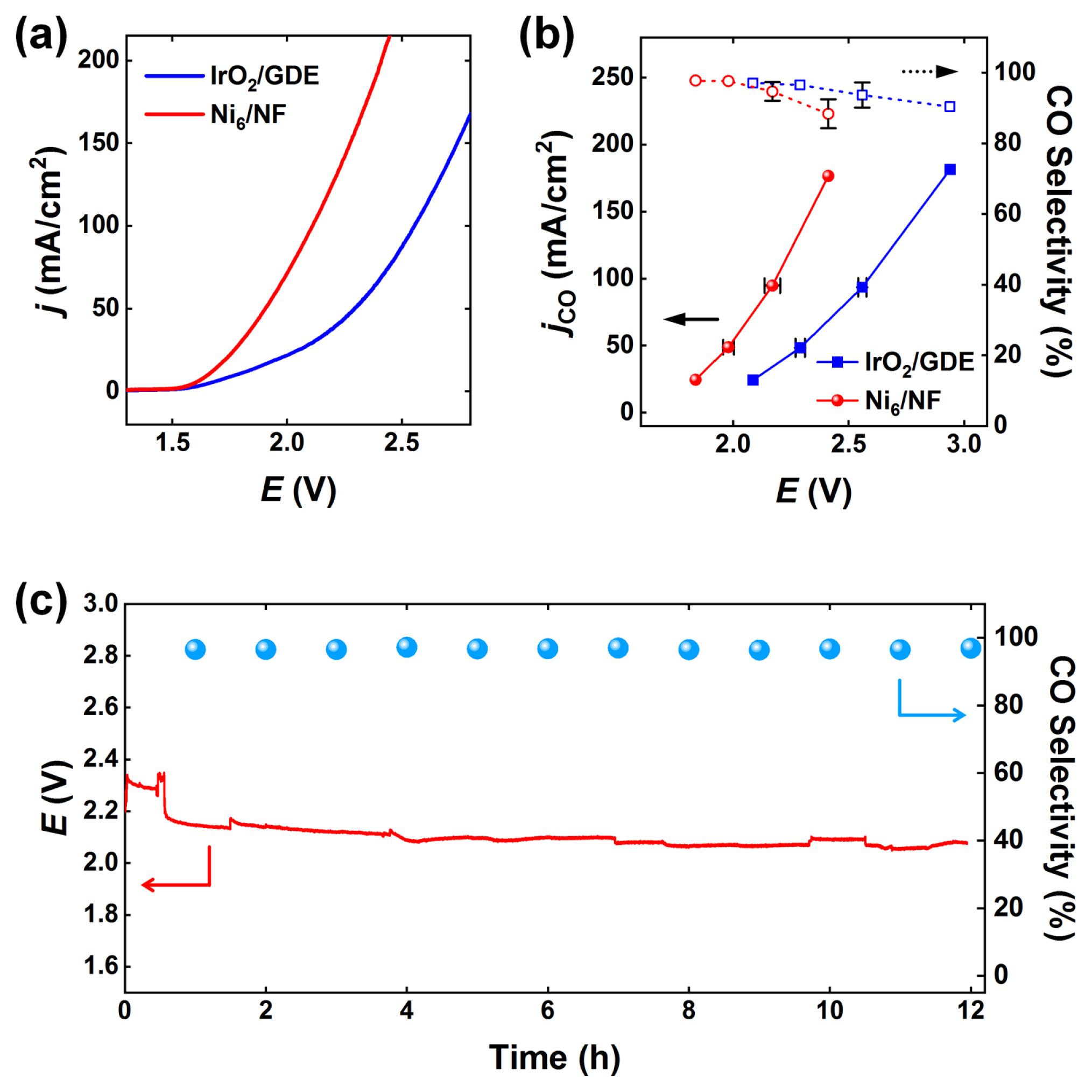
To evaluate the feasibility of Ni6/NF in CO2 electrolysis, the Ni6/NF anode was coupled with a Au25/GDE cathode in a zero-gap CO2 electrolyzer (see the Experimental Section for details). Ni6/NF exhibits higher cell activity than that of the IrO2/GDE (Fig. 4a). The cell potential obtained using the Ni6/NF anode was approximately 0.4 V smaller than that of IrO2/GDE at a current density of 100 mA/cm2. We performed CP experiments and GC analyses to confirm the origin of the cathodic currents. Fig. 4b shows the partial current densities and selectivities for CO and H2 measured using the zero-gap CO2 electrolyzer. Regardless of the anodes, Au25/GDE exhibits high selectivity for CO production; however, the cell potentials were reduced by more than 0.4 V with Ni6/NF due to reduced OER overpotentials. Furthermore, a long-term stability test of Ni6/NF was conducted at 100 mA/cm2 (Fig. 4c). During the initial operation (~2 h), the cell potential gradually decreased owing to the activation of the electrodes. The electrolyzer then sustained its reactions at a cell potential of ~2.0 V for 12 h, maintaining a CO selectivity above 95%. The energy efficiency of CO2-to-CO conversion at 100 mA/cm2 is above 63%, which is higher than those reported for the most efficient electrocatalysts to the best of our knowledge [57–60].
4. Conclusions
We demonstrated that the dip-processed Ni6/NF electrode exhibits exceptional OER activity in alkaline media. The Ni6/NF electrode was fabricated by simply dipping NF into the NC suspension. The Ni6/NF electrode showed higher OER activity than those of IrO2/GDE and Ni6/GDE without corrosion under oxidative conditions. Tafel analysis and EIS revealed that fast electron transfer on Ni6/NF resulted in enhanced kinetics during the OER. The zero-gap CO2 electrolyzer with the Ni6/NF anode was stably operated at a current density of 100 mA/cm2 for 12 h while maintaining a cell potential of ~2.0 V and CO selectivity above 95%. This study provides a useful methodology for the facile and uniform preparation of NC-catalyst-coated electrodes.