1. Introduction
Renewable electricity will dominate future energy infrastructure to replace conventional fossil fuels. Electricity-associated services, such as production, storage, and applications, supply the demands of human daily life and well-being, industries, and economic progress. Therefore, securing sustainable and carbon-neutral electricity generation is very important in the future. Extensive research has been conducted to replace the conventional fossil fuel-based power station with more sustainable and environmentally friendly alternative renewable energy systems that alleviate pollutants released to the environment [1].
Bioelectrochemical systems (BES) have been highlighted as potential converters for renewable electrical energy [2ŌĆō5]. Microbial fuel cells (MFCs) produce bioelectricity from various organic matter, including biomass and wastewater. The electroactive bacteria convert various organic feedstock into bioelectricity. Therefore, MFCs have been applied to sustainable wastewater systems since the 1990s. On the other hand, the scalability and commercial viability of MFCs have been a concern regarding cost-effective materials and reactor configuration [6]. The proton exchange membrane (PEM) is one of the essential components in determining the MFC performance and capital cost. The proton and cations produced in anode chambers by the bacterial oxidation of organics should be transported to the cathode chamber through an ion exchange membrane while being able to prevent oxygen and substrate crossover [7ŌĆō9]. NafionTM is the most widely used membrane for MFC applications owing to its good stability and electrochemical performance. Nafion consists of a perfluorinic acid (PFSA) structure with SO3H (sulfonic acid) groups that provide ideal properties, such as high proton transfer and ion exchange capacity, thermal and chemical stability, with an appropriate mechanical strength [7,10ŌĆō13].
Nafion membranes account for approximately 40% of the total cost of an MFC reactor [14,15], which has motivated researchers to develop alternative ion exchange membranes and separators. Chitosan (CS) is a natural biopolymer and the second largest abundant biomass on earth [16]. CS has been considered a potential replacement for Nafion because of its biodegradability, high biocompatibility, thermal and chemical stability, and low cost [17ŌĆō19]. Therefore, CS has been investigated as an alternative membrane for MFCs [16,20ŌĆō22]. On the other hand, poly(vinyl alcohol) (PVA) is a non-toxic, low-cost polymer with excellent mechanical properties that can be molded easily into flexible and resistant films. On the other hand, PVA exhibits low proton conductivity and electrochemical properties because it lacks charged functional groups within the structure [23]. In previous studies, PVA blended and crosslinked with CS increases the conductivity and physiochemical properties of the ion exchange membrane [14,24]. The PVA/CS polymer-composite membrane was used as an ion exchange membrane for various fuel cells [23ŌĆō28] to show advantages, such as low fabrication costs [25] and reduced environmental impact because of biodegradability and low disposal cost [29]. Gonz├Īlez-Pab├│n et al. used PVA/CS in a microbial electrolysis cell among various bioelectrochemical systems for hydrogen production as an ion exchange membrane (H2 production rate of 1277┬▒46 mL H2LcatŌłÆ1dayŌłÆ1) [26]. The optimal mixing ratio between PVA and CS needs to be determined for use in bioelectrochemical systems, such as MFC.
This study is the first to evaluate the performance of PVA:CS membranes as an alternative to Nafion for bioelectricity production in MFCs and optimize the mixing ratios of PVA and CS for higher performance. Five different membranes (PVA:CS with different ratios of 1:1, 2:1, and 3:1 and CS-only and PVA-only as controls) were synthesized and examined. The water uptake, ion exchange capacity, Fourier transform infrared spectra, surface morphology, and MFC applications were compared with the commercialized Nafion membrane.
2. Experimental
Poly(vinyl alcohol) (PVA, 99.0ŌĆō99.8 mol% hydrolyzed) and chitosan (CS, deacetylated chitin (poly ╬▓-1,4-D-glucosamine, Ōēź75% deacetylated) were acquired from Sigma-Aldrich. Sulfuric and acetic acids from Samchun Pure Chemicals (South Korea) and Acron Organics (Czech Republic) were used as the synthesis solutions. All solvents and chemicals for the experiment were of analytical reagent grade. Distilled and deionized water from a Millipore Milli-Q system were used to prepare all experimental solutions and electrolytes. The Nafion membrane from DuPont Co. was used as received.
PVA-only, CS-only, and PVA:CS membranes were synthesized by casting the solutions on a Petri glass dish and the solvent evaporation technique, based on methodologies reported by Mukoma et al. [21], Rudra et al. [28] and Gonz├Īlez-Pab├│n et al. [25]. The synthesized membranes were washed thoroughly with deionized water and stored in Petri glass dishes at room temperature before the experiments.
The CS-only membrane was prepared by dissolving six grams of chitosan powder in 300 mL of a 2% v/v acetic acid solution to produce a 2% w/v aqueous chitosan solution and stirred at 1000 rpm at 40┬░C. Once the chitosan was dissolved, the solution was centrifuged at 8500 rpm for 60 minutes to allow the undissolved particles to settle. The resulting solution was kept at 4┬░C for 24 h. Subsequently, 20 g of the CS solution were cast on a Petri glass dish, kept at room temperature for 24 h, and dried in an oven at 60┬░C for 6 h. A 2 M solution of NaOH was used to neutralize the dried membranes for five minutes, followed by washing with deionized water. The membranes were then immersed in 0.5 M H2SO4 for 24 h to crosslink.
The PVA-only membrane was prepared by dissolving 30 g of PVA powder in 300 mL of deionized water to produce a 10% w/v aqueous solution of poly(vinyl alcohol) and stirred at 500 rpm at 80┬░C for 2 h. The PVA film that formed on top of the solution was removed and discarded. Once the PVA was dissolved completely, the solution was cooled to room temperature before being kept at 4┬░C for 12 h. Subsequently, 20 g of the PVA solution were cast on a Petri glass dish and dried at 60┬░C for 6 h in an oven. A 10% v/v H2O2 solution was used to prevent the dissolution of the PVA membrane during crosslinking with sulfuric acid. The membrane was immersed for one hour and washed with deionized water. The membranes were immersed in H2SO4 0.5 M for 24 h to crosslink.
The aqueous CS and PVA solutions were mixed at different proportions (PVA: CS 1:1, 2:1, and 3:1), stirred at room temperature at 500 rpm for 2 h, and the resulting solutions were kept at 4┬░C for 24 h. Twenty grams of all PVA:CS solutions were cast on a Petri glass dish, kept at room temperature for 24 h, and dried in the oven at 60┬░C for 6 h. A 2 M NaOH solution was used to neutralize the dried membranes for 5 min, followed by washing with deionized water. The membranes were then immersed in 0.5 M H2SO4 for 24 h to crosslink.
A two-chamber microbial fuel cell reactor was assembled to evaluate the performance of each PVA: CS membrane as PEM, and the commercialized Nafion membrane was compared. The MFC reactor consisted of two 250 mL borosilicate glass chambers, where 4 cm2 of each membrane were used. Both chambers were joined by a clamp and separated by the synthesized membranes (PVA:CS). The anode and cathode electrodes consisted of graphite felt with dimensions of 4 cm├Ś3 cm (G200, Fuel Cell Store, USA) and connected to a 1 k╬® resistance through a titanium wire working as a current collector by an external circuit. In the anodic chamber, the anolyte solution consisted of the following: CH3COONa, 3.28 g LŌłÆ1; NH4Cl, 0.23 g LŌłÆ1; NaCl, 0.04 g LŌłÆ1; MgSO4┬ĘH2O, 0.01 g LŌłÆ1; KCl, 0.02 g LŌłÆ1; yeast extract, 0.01 g LŌłÆ1. A 50 mM K3[Fe(CN)6] solution in 50 mM phosphate buffer was used for the catholyte. The anodic chamber was bubbled with 100% N2 for 20 min to achieve anaerobic conditions. The inoculum was a secondary anaerobic digester sludge collected from a wastewater treatment plant (Suyeong WWT Plant, Busan, Korea). The MFC reactors were operated in an incubator (SW-90S, Sangwoo, Korea) at 30┬░C in batch mode. The voltage of the MFC was monitored using a multimeter connected in parallel to the electrodes to measure the voltage values.
The water uptake was assessed by comparing the changes in the weight of the membrane in wet and dry states using the methodologies reported by Srinophakun et al. [16], Kim et al. [30], and Gonz├Īlez-Pab├│n et al. [25]. Membrane samples of 1 cm2 were left to dry at 60┬░C for 6 h and weighed as the dry weight (wdry). They were immersed in deionized water to rehydrate at ambient temperature for 1 min. The excess water was wiped off using tissue paper. The membranes were weighed again, and the wet weight (wwet) was recorded. This process was repeated at different times to determine and evaluate any significant changes in the water absorption after prolonged periods to emulate the batch operation conditions. The wet weight was recorded after 1, 5, 10, 60, and 1,440 min (24 h). Equation (1) shows the calculation of the water uptake percentage (W %):
The protocol described by Wang et al. [31] involving an acidŌĆōbase titration was followed to determine the ion exchange capacity (IEC) of the membranes. Square samples of the dry membrane (4 cm2 in size), were cut, weighed, and immersed in a 1 M H2SO4 solution for 24 h for protonation. Subsequently, they were washed and immersed in 50 mL of a 1 M NaCl solution for another 24 h, where the H+ protons were released. The membranes were removed, and the NaCl solution was titrated using a 0.01 M NaOH solution as the titrant with two drops of phenolphthalein as an indicator. The titration was performed in triplicate. The ion exchange capacity of the membranes, expressed in milliequivalents of H+ per gram of mass, was determined using Equation (2):
where V is the volume of titrant used in mL; C is the concentration of the titrant used for the titration; w is the dry weight of the membrane in grams.
FT-IR (Spectrum GX, PerkinElmer) spectroscopy using the attenuated total reflection technique (ATR) was used to identify the functional groups present in the CS, PVA, and PVA:CS blends to determine the chemical properties of the membranes. The measurements were conducted within the wavenumber range of 400ŌĆō4000 cmŌłÆ1. Scanning electron microscopy (SEM, VEGAII LMU, Tescan, Czech) was carried out to analyze the surface morphology of the PVA:CS Membrane. The samples were coated with gold nanoparticles using a sputter coater (E-1010, Hitachi). The SEM images were obtained at 5 kV.
Bioelectricity generation of the MFCs was measured manually using a multimeter connected in parallel to each reactor. The current (I) was calculated, as shown in Equation (3):
where I is the current; V is the voltage; R is the external resistance. Power (P) was calculated, as shown in Equation (4):
The polarization data (Power density) were also obtained manually using an external load resistance box (RBOX 408, Lutron, Taiwan) from 100 k╬® to 100 ╬® with sufficient transition time (from 30 min to 1 h). The power density was obtained based on the fuel cell dimensions expressed in mW cmŌłÆ2. These values were obtained using the geometrical area (A) of the electrode (12 cm2).
3. Results and Discussion
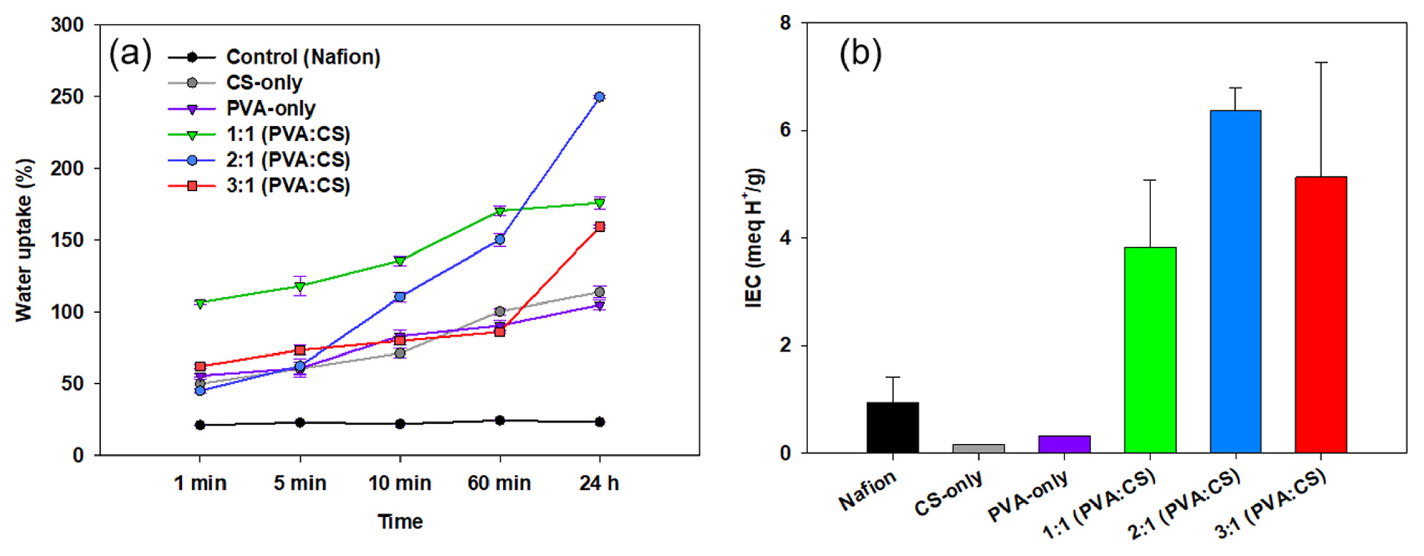
Fig. 1(a) presents the water uptakes of all the prepared membranes compared to Nafion. The PVA:CS composite membranes immediately absorbed water within several minutes compared to Nafion. The membranes with a larger proportion of PVA to CS (2:1 and 3:1) gained 53.3┬▒7.4% of their dry weight within the first minute after immersion into water. In contrast, the 1:1 membrane gained more than 100% of its dry weight within the same time frame. The three composite membranes (1:1, 2:1, 3:1 of PVA:CS) displayed a water uptake percentage of more than 100% after 24 h of hydration. The 2:1 PVA:CS membrane was the highest percentage of 249.9%. The water uptake of Nafion was only 22.9┬▒1.2%, which can be attributed to the low concentration of hydrophilic groups in the structure, compared to PVA:CS [25]. The water uptake is an important characteristic of an IEM as water molecules facilitate the transport of protons through the membrane [32] and are closely related to the ion exchange capacity of the membrane within the electrochemical system [33]. The hydration capacity of the membranes is generally determined by their hydrophilic groups, as the presence of hydroxyl (ŌĆōOH) and amine (ŌĆōNH3) groups increases ionic transport [23].
The ion exchange capacity (IEC) provides an estimation of the proton conductivity through the polymer structure, significant ly influencing the electrochemical performance of an ion exchange membrane in electrochemical systems [34]. The membranes with a high proportion of PVA to CS displayed a higher IEC than the CS-only and PVA-only membranes (Fig. 1(b)). The IEC of Nafion in this work was close to the values reported by Witt et al. of 0.8 to 1.0 mEq. H+ gŌłÆ1 [23]. The CS-only membrane showed a similar value to that reported by Holder et al. of 0.24┬▒0.28 mEq. H+ gŌłÆ1 [20]. The PVA-only also showed a similar value to Rudra et al. (0.16 to 0.25 mEq. H+ gŌłÆ1) [28]. The PVA-only membrane has a low value of IEC, which can be attributed to the major ŌĆōOH groups, but there were no polarizable sites within the structure [27]. The PVA:CS composite membranes showed high IEC values, which can be introduced to the ŌĆōSO3H group by crosslinking.
All the synthesized PVA:CS membranes had higher water uptakes and IEC values than Nafion. The higher hydration capacity facilitates the formation of hydrophilic tunnels between clusters to increase the proton and ion transportation within the membrane structure [35,36] as the hydrophilicity of the synthesized membrane reduces the ion transport resistance to increase ion conduction [37]. In addition to the hydration capacity and IEC, the mechanical properties of the membrane are important factors to consider for applications in realistic electrochemical systems. The water uptake increases swelling and morphological deformation of the membrane by decreasing the tensile strength, which could lead to the crossover of oxygen and substrate and simultaneously reduce the selectivity of proton crossover. Holder et al. reported that a low water uptake (below 59.5%) could reduce the risk of cation crossover [20]. The mechanical strength of the PVA:CS membrane is relatively lower than the Nafion due to high hydration. On the other hand, it may be applicable to MFC applications, which generate low power and voltages under mild operating conditions.
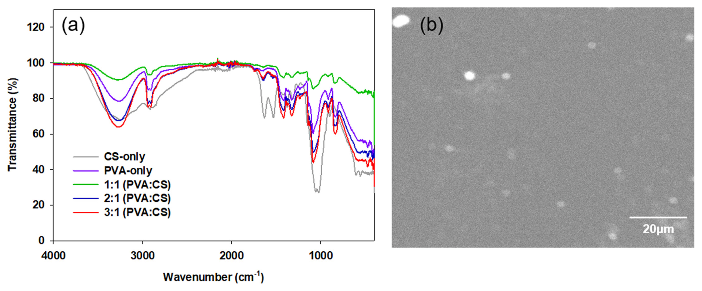
FTIR-ATR spectroscopy was carried out to identify the functional groups of the membranes. Fig. 2(a) shows the FTIR spectra of CS-only, PVA-only, and PVA:CS membranes. The broad bands visible at approximately 3200 to 3300 cmŌłÆ1 were assigned to the NH and polymeric OH stretching vibrations and intra-molecular hydrogen bonds [38,39]. The bands between 2950 and 2900 cmŌłÆ1 indicated the methylene CŌĆōH asymmetric/symmetric stretching vibrations. The peaks at 1550 and 1470 cmŌłÆ1 were attributed to the stretching vibrations of primary (1550 cmŌłÆ1) and secondary (1470 cmŌłÆ1) amide groups [40]. The peaks at 1100ŌĆō1030 cmŌłÆ1 were attributed to the ŌĆōSO3H group symmetric stretch introduced by crosslinking, which confirms the presence of sulfonic acid [41,42]. The IEC values and FTIR-ATR results support the crosslinking reactions in all membranes caused by NH2 groups and their interactions with chitosan and the SO42ŌłÆ group [25]. The spectra of the PVA:CS membranes presented the distinctive peaks of its components due to the signals of CS, PVA, and SO3H as the crosslinking agent. The usual bands of absorption associated with the CH2 methylene groups of PVA and CS, as well as the OH stretching in PVA and the -NH stretching in CS, were also observed.
The SEM image of the 3:1 PVA:CS membrane revealed a smooth and non-porous surface that was attributed to the PVA, whereas a rough and porous structure with some crystals was observed from CS-only (Data not shown) (Fig. 2(b)) similar to Gonz├Īlez-Pab├│n et al. [25]. The smooth and uniform morphology is believed to increase ion transport and conductivity, as reported previously [43,44]. Such a smooth surface of the composite membrane is also expected to prevent biofouling in the MFC system [25]. Antolini et al. reported that smoother membrane surfaces resulted in less probability of biofouling than the rough and porous counterparts [45]. The composition of PVA and CS can provide a better morphological structure to implement into MFCs and other electrochemical systems.
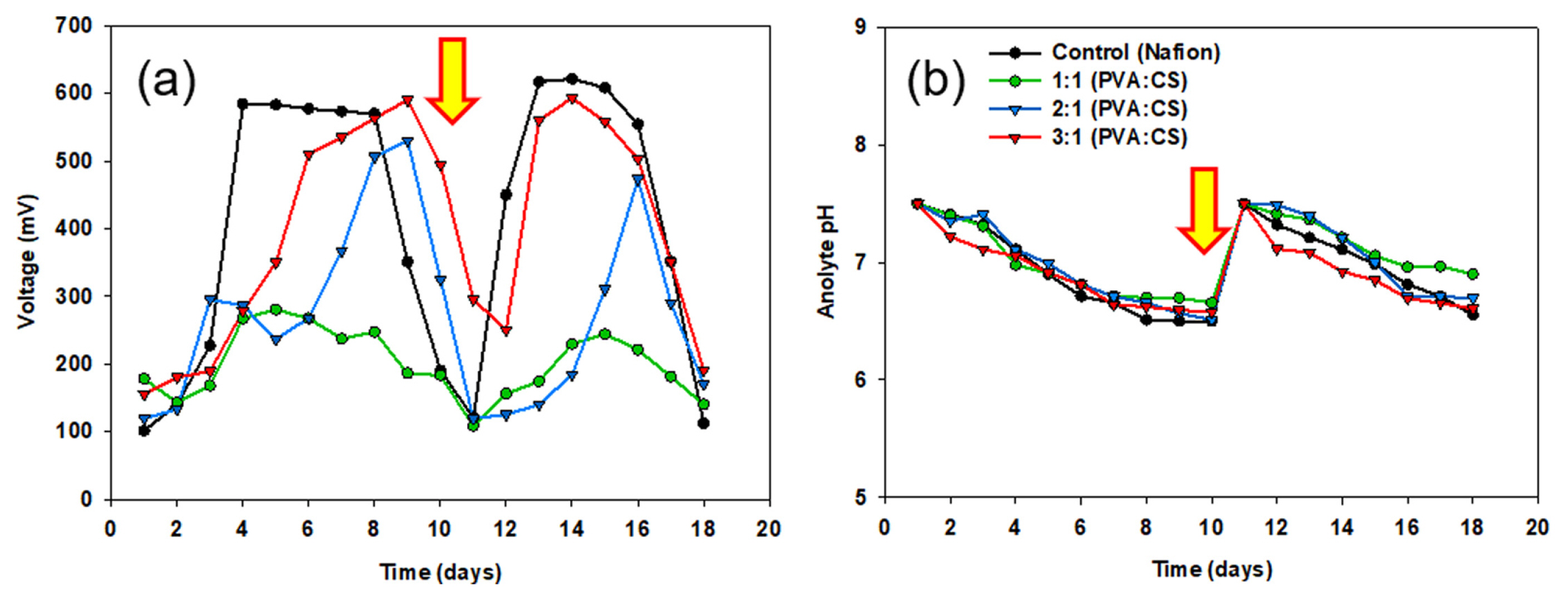
The developed PVA:CS membranes were applied to two-chamber MFC reactors to examine bioelectricity generation. The performance of each reactor was evaluated in two batch cycles (9 days each) for 18 days. The voltage of the MFC with the 3:1 (PVA:CS) membrane reached 510 mV in the first cycle, and the maximum voltage was 590 mV. In contrast, the 1:1 and 2:1 membranes showed relatively lower voltage generation (280ŌĆō530 mV), and slower start-up, as shown in Fig. 3(a). The 2:1 PVA:CS membrane has the highest water uptake and IEC values but is unsuitable as an MFC. Sigwadi et al. assessed zirconium phosphate (ZrP) incorporated in Nafion for improved ion exchange membrane properties for fuel cell applications. Among the various mixing ratios of Nafion/7.5% ZrP, the water uptake and IEC value were the highest, but for the fuel cell performance, the cell performance was lower than that of Nafion/5% ZrP with a low mixing ratio (112.6 mW cmŌłÆ2 vs. 145 mW cmŌłÆ2) due to mechanical defects, such as agglomeration [46]. From this, the water uptake, IEC values, and mechanical strength should be harmonized for functionalized as an ion exchange membrane. At the end of the cycle, the voltage decreased due to the depletion of the carbon substrate in the anodic chamber. In the second cycle, after media replacement with substrate supplementation, the MFC with Nafion membrane achieved a maximum voltage of 621 mV, whereas the 3:1 PVA:CS membrane reached 593 mV, which was comparable to Nafion. The bioelectricity generation of PVA:CS was maintained throughout the repeated medium replacement in MFC.
All the MFC reactors showed a decrease in pH in the anodic chamber by acidification because of substrate oxidation at the end of each batch cycle (Fig. 3(b)), whereas the pH of the cathodic chamber increased in all reactors. A similar pH gradient was reported elsewhere [15,47], and it was expected during the operation of an MFC because of the different electrochemical processes in each compartment. At the anode, the microorganisms use organic matter as an energy source, producing protons (H+) and electrons (eŌłÆ) as byproducts of an oxidation reaction. The protons released into the anolyte frequently increase the acidity to lower the pH. At the cathode, however, the electrons introduced from the anode through an external circuit react with oxygen; simultaneously, the protons are consumed to form water molecules. This oxygen reduction reaction (ORR) increases the pH by consuming protons in the catholyte with increasing alkalinity.
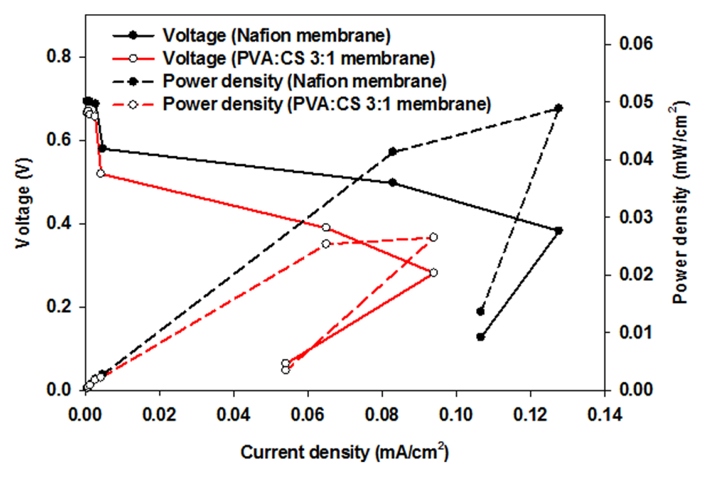
Fig. 4 shows the power density and polarization curve of composite membrane-implemented MFCs. The maximum power density was achieved by the 3:1 PVA:CS membrane of 0.026 mW cmŌłÆ2, which was lower than that of Nafion (0.048 mW cmŌłÆ2). Considering the manufacturing cost and use of biodegradable materials, the PVA:CS composite membrane is applicable to MFC systems to generate bioelectricity from organic matter. Further improvement of the electrochemical performance by fabricating and casting composite membranes will provide a strategy for realistic applications of MFC.
4. Conclusions
Different mixing ratios of PVA to CS were examined to optimize the ratio for bioelectricity generation for the MFCs system. The PVA:CS membranes showed higher water uptake efficiencies and IEC values than Nafion. The optimal PVA:CS mixing ratio was 3:1 to produce comparable bioelectricity generation during MFC operation (18 days). The maximum power density of the PVA:CS membrane was 0.026 mW cmŌłÆ2, which is comparable to Nafion (0.048 mW cmŌłÆ2). These results show that PVA:CS composite membrane can be an alternative option to the commercialized Nafion membrane because of their low cost, high biodegradability, and eco-friendly manufacturing.