1. Introduction
Global production of Li-ion batteries has increased exponentially with increase of market share of the electric mobility, portable electronic devices, health care tool kits and energy storage solution. The global market of Li-ion batteries is estimated to be over $115 billion by 2030 [1]. The global climatic policies are encouraging to harness the renewable energy. Consequently, demand for storage of this energy for effective utilization of renewable energy is high. Globally, the large storage capability (of Li-ion) technologies with high volumetric and high gravimetric energy densities are gaining momentum for eliminating the range anxiety of e-vehicles (EV).
Currently, lithium cobalt oxide (LCO), also known as mature cathode chemistry, is the most common consumer electronics battery technology. This chemical, however, is not suited for EV applications because to its structural instability in terms of excess delithiation [2]. Also, other chemistries are abundant resources, stable crystal structures, and low price, such as lithium iron phosphate (LFP), lithium nickel manganese cobalt oxide (NMC), lithium nickel cobalt aluminium oxide (NCA), and spinal lithium manganese oxide (LMO) have become dominant battery materials for automotive applications compared to LCO. Among the wide range of Li-ion cathode chemistries, researchers are focusing on Ni-rich (Ōēź80%) ternary layered metal oxides systems such as LiNixCoyMnzO2 (NCM) and LiNixCoyAlzO2 (NCA). Over the last two decades, layered Ni-rich (NCA) cathodes have been widely developed to satisfy the energy density criterion due to their high theoretical capacity of 275 mAh/g [3ŌĆō5]. The main reason for power fade and capacity decay are mostly caused by high interfacial resistance at the cathode, whereas polarisation and overpotential are primarily caused by the development of NiO structures on the surface at extreme temperatures (>60┬░C). NCA is safer than other battery materials in a certain condition, owing to its high tolerance of overcharge and somewhat lower potential at full charge. Additionally, compared to NMC811, the removal of manganese improves capacity retention while the addition of aluminium ions (Al3+) seeks to reduce harmful phase transition, enhance thermal stability, and raise operation voltage (via the weakening of the Ni-O bond by the stronger Al-O bond) while lowering overall cost [6]. Tesla launched its first Roadster ŌĆ£long-range EVsŌĆØ in 2006, powered by Panasonic cylindrical 18,650-type Li-ion batteries with NCA cathodes. Tesla vehicles (the Model S-2010, Model X-2015, and Model 3-2017) and other cars like as the Mercedes-Benz S400, Toyota RAV4 Hybrid, and VW E-Golf use the NCA/C chemistry [7]. To date, At the cell level (18650-type cells), the largest volumetric and gravimetric energy densities to date are 670 Wh/L and 250 Wh/kg, respectively [8]. By 2025, the energy density of NCA technology is expected to reach 700 Wh/L and 300 Wh/kg [9].
Preparation of the electrode and assembly to cell production are both critical to achieving optimal performance of the Li-ion battery as designed. Li-ion cell manufacturing methods include various phases, from electrode formula preparation through final cell finishing. Among the procedures, one of the most crucial phases is the creation of the cathode electrode slurry, which has a considerable impact on the attributes of the Li-ion cell. The charge transfer kinetics are directed by both electronic and ionic transportation, which is determined by the electrode composition and technique of manufacture [10]. Therefore, effective mixing of the electrode slurry is to optimize the processes for improving performance of the cell and benefit the scale up of production.
NCA cathode is considered in this current study to investigate the slurry fundamental characteristics. Cathode electrode slurry is a non-equilibrium mixture of solid content and liquid solvents. Particles of solid material are distributed from micron to submicron size in the composite containing an active material, conductive carbons, along with polymer binder solution. The cathode electrode consisting of the active material is the major percentage in the cell which contribute to the capacity of the cell. Conductive additives and polymeric binder in the electrode vary from 3 to 10% to the total weight of the cathode electrode solid composition. Therefore, the electrode slurry properties depend on the composition, particle size, electrode slurry preparation process and rheology properties of the electrode slurry. Hence, achieving well dispersed slurry with viscous N-methyl-2-pyrrolidone (NMP) solvent has gained attention in the slurry preparation process [11,12].
Man Kim et al., reported the benefit of mixing the solid Lithium cobalt oxide (LiCoO2; LCO) electrode mixture with the binder solution (PVDF+NMP) and then adding the solvent for a homogeneous mixture. The test results showed improved cycle performance as compared to the other method of mixing [13]. Lee et al., studies also revealed the superior capacity and stability in case of multi-step addition of the NMP solvent to the LCO electrode slurry [14]. Further, multiple-step addition of solvent using high shear processes have shown controlled dispersion of the particles in the electrode slurry.
As far as concerns, Ni rich Lithium-ion batteries shows higher specific capacity and higher operating voltage. Ni rich NCA has higher rate capabilities than other Ni rich chemistries [15]. However, at a high working temperature, the increase of impedance and the poor thermal stability of NCA often lead to a significant capacity fading, especially high charge/discharge rates [16]. Recently, more investigation on NCA for capacity fading mechanism and new trends on addition of gel-electrolyte for superior capacity and safety [17,18]. NCA materials are more prone to deleterious cracking than NMC. The facts that solving these Ni-rich chemistries are subject to analyses.
However, up to our knowledge no research was conducted to determine what function on step wise addition of NMP in enabling electrochemical performance. The interactions between PVDF, NCA, and the other electrode components are investigated in this work to offer a better scientific explanation of why this binder was effective in early testing. Because step-by-step addition is a reasonably simple, drop-in solution that might be used in industry, actual cell conditions are taken into account. Cathode areal capacities of 1.5Ah for cylindrical cell and pouch was based fabrication with graphite anode with a negative-to-positive capacity (N:P) ratio of 1:1.15, and calendared electrodes with 32ŌĆō33% porosity are employed.
In this paper, we report sequential addition of NMP solvent to prepare the Ni-rich NCA electrode slurry and its effect on slurry rheology and cell performance. The Li-ion cells are tested at ambient temperature and the multi-mode/sequential addition of NMP solvent to the electrode slurry shows an improved performance as compared with single step process by electrochemical impedance spectroscopy analysis. The benefit of multi-step addition over the single step addition of solvent to the electrode slurry while stirring, rheology of the resulting slurry and its impact on the cell performance are discussed.
2. Experimental
2.1 The slurry preparation
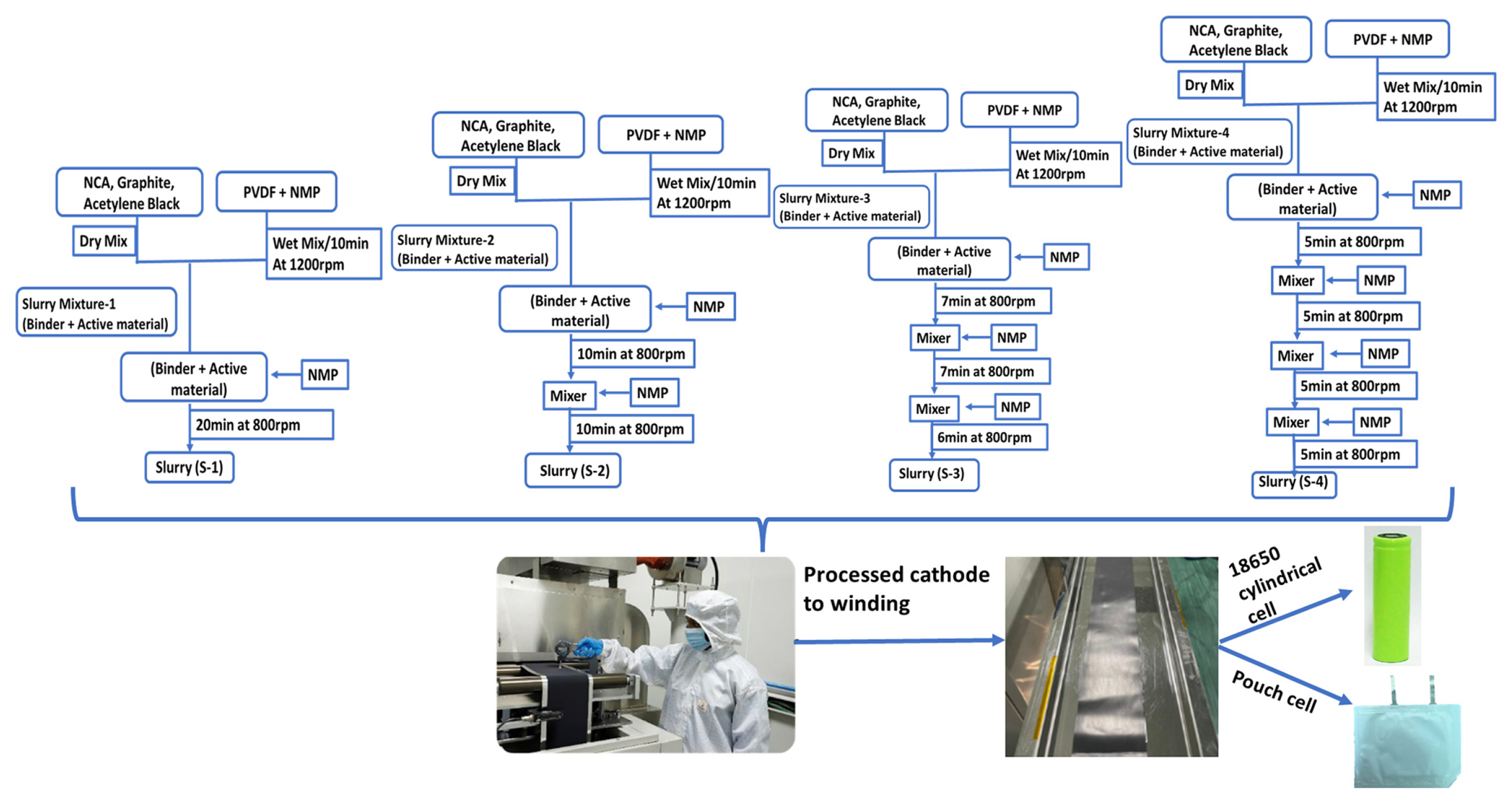
In order to prepare the 500 g of total solid material contained cathode slurry, a solid composition of Ni80Co15Al0.5 (NCA 90 wt.% (Toda, Japan), 1% Graphite (G) (Graphite KROPFMUHLAG, Germany), 3% acetylene black (AB) (SN2A, France) and 6% PVDF (Kureha Corporation, Japan) was chosen. Accordingly, NMP (Sigma Aldrich) was added to the slurry preparation. The solid to liquid composition ratio was maintained as 60:40 (wt.%). The slurry preparation was initiated with a binder preparation by dissolving required amount of the binder (6% PVDF) in ~195 mL (60 vol.% of total 324 mL NMP). In addition, the solution was mixed at 1200 rpm for 10 min to prepare homogeneous binder using the planetary orbital mixture (Thinky Corporation, ARV-930 twin model, Japan).
The mixture of NCA, G and AB were dry mixed separately during the binder preparation using a dry mixture. The resultant dry mixed solid composition mixture was added to the binder solution and allowed for stirring with the sequential addition of NMP. Left over 129 mL NMP (40 vol.% in total NMP volume) was added to the slurry at different time intervals. Four different addition processes were tried to identify the effect of the sequential addition of NMP. The total planetary stirring/mixing time and the total added volume of NMP are kept constant and the interval time and NMP volume at each interval were varied as shown in Fig. 1. In the first method and the single step method, the required (129 mL) NMP was added to the slurry after stirring of binder and the dry mixed cathode solid composition (slurry mixture-1) and then allowed for 20 min planetary stirring at 800 rpm. In the two-step process, the total NMP was separated into two equal parts and the first addition was done into the slurry mixture-1 initially and allowed for 10 min stirring at 800 rpm and then the remaining amount was added and allowed for second 10 min stirring. Three and four step NMP addition process was done. The finally prepared four resultant cathode slurries were denoted as S-1, S-2, S-3, and S-4 (where S indicates the sequence and the number (1 to 4)) represents the number of NMP addition sequence steps in Fig. 1.
2.2 Rheology studies
The electrode slurry properties are primarily evaluated by measuring the slurry viscosity and viscoelasticity. These properties are critical for understanding the fluid flow properties of the electrode slurry while pasting on the Al current collector. Viscosity measurements were carried out on Anton Paar Rheometer MCR 72ŌĆō92 with a cone and plate configuration. The system is set at an angle of 4o, radius of 20 mm, truncation of 40 mm, and measuring position gap of 0.4 mm. Viscosity measurements were conducted at a constant temperature of 25┬░C controlled by several air-cooled Peltier temperature units. For each sample, ~3 mL of slurry sample was used and measured the viscosity was in a shear rate of 0.1 to 100/S. Viscoelasticity study carried out with angular frequency sweep test was in the range of 0.1 to 100 rad/s.
2.3 Characterization of electrode materials
2.3.1 Sample preparation for peel strength and calendaring
The cathode electrode slurry coated on Al current collector and pasted on stainless plate with tape. In order to employed with UTM Tinius Oslen 25ST and standard of ASTM D903. The length and width of electrode 150 mm and 25 mm with applied tension of 5N holder with take up load of 1 N and test speed 20 mm/min. By averaging the horizontal forces experienced during the peel mode and dividing that result by the blade width, the adhesion strength can be determined. In order to get more accurate findings, at least three measurements were made for each sample.
The electrodes were calendared by a pilot scale two roll with continuous process (Sunte, China). The two identical rolls measure 300 mm in diameter and 210 mm in width. The maximal applicable line load is 15 kN/mm and speed are 0.5 m/min. The applicable electrodes were calendared at dry room conditions and had 180 mm coating width of electrode with variable thickness. In order to apply the various line loads, the spacing size between the rollers was changed. Once compaction process completed the material kept for drying vacuum drying at 80┬░C.
The density of the electrode is defined by volumetric mass density of the electrode material (mixture of active material, binder, and conductive agent). Ensure the thickness of the electrode ╬┤E and mass loading of electrode mL. The density of electrode Žü measured in the given below equation [19]:
2.3.2 Sample preparation for SEM
The cathode electrode slurry was coated on the Al current collector using reverse coma coating machine. This electrode film was dried in the vacuum oven at 80┬░C for 12 h and resultant electrodes were calendared for densification of the electrode. In order to examine the morphology of the electrode samples, the scanning electron microscopy (SEM) (JSM-7800F, JEOL) was employed to identify the morphology and material distribution in the cathode. The samples were prepared by sputtering gold on the coated electrodes. The samples with dimensions of 10 mm circular diameter electrode were used for capturing the images of electrode samples. The SEM images were obtained using a secondary electron detector at accelerating voltages in the range between 4 and 20 kV.
2.3.3 Sample preparation for EIS
The electrochemical impedance spectroscopy (EIS) studies were carried at room temperature on the Li-ion pouch cell type configuration to estimate the internal resistance of the cell. The EIS studies were carried out at a wide frequency range from 10 kHz to 10 Hz with the amplitude of 10 mV using the impedance analyser (Model: BCS 810 Biologic, France) at room temperature. The impedance profile is used to analyse the electrode rheology and cell performance for the single and multi-stage addition of solvent to the cathode electrode mixture of the Li-ion cell.
2.4 Fabrication of Li-ion cells
The Li-ion cell assembly was carried out in an environmentally controlled atmosphere, subjected to calendaring the electrodes prepared by single and different sequential addition of solvent. In-house made anode and a porous tri-layer poly propylene/polyethylene/polypropylene (2320, Celgard, USA) separator was used between the cathode and anode to prevent internal shorting of the cell. For preparation of the 18650 cylindrical cells, the calendared cathodes were used to prepare the cylindrical cell electrodes. The required length and width of the electrodes were achieved by vertical and horizontal slitting, respectively. Counter anode electrodes were prepared with graphite active material for different kind cathode electrodes. The Al and Ni tabs are welded to the bare area of the current collectors of cathode and anode electrodes respectively using the ultrasonic welding. The tab width 4 mm, thickness 0.1 mm and length 80 mm were used and welded in the energy mode for cathode 12 J and anode 18 J. The separator was wrapped between the two electrodes to the ionic flow between the electrodes during the charge and discharge processes. The anode and cathode electrodes are separated by two layers of separators used to prepare the jelly roll and the resultant jelly roll was inserted into the cylindrical can. The anode tab was welded at the bottom position of the cell and the cell was grooved to maintain the jelly roll structure. The cathode tab was welded to the top lid by resistive welding. 4 mL of electrolyte used is a mixture of the lithium slat and organic solvents (1.0 M LiPF6 in EC: DEC: EMC, Kishida Chem. Corp., Japan) in the 1:1:1, molar volume (v/v%) followed by crimping the cell to form a cylindrical cell. During electrolyte filling 60 kPa pressure was maintained. The battery was kept aging for 48 h. A similar procedure was adopted to fabricate the pouch cell with anode and cathode electrodes being prepared by both single and multi-step processes (referred to as S-1, S-2, S-3, and S-4). We fabricated single stack pouch cell with the dimension of cathode (4 cm to 3 cm). The cathode loading of S-1 to S-4 are ~9.5 mg/cm2 and anode coating is adjusted with cathode capacity. Then selected dimension are stacked with tri-layer separator and the suitable tabs are welded with corresponding electrode. After that, entirely covered with aluminium laminated pouch (grade PET C8) with 150 ╬╝M and it was degassed. Then electrolyte added under vacuum conditions sealed the pouch cell for further analysis. These cells are used to measure the EIS and charge discharge performance of the cells at ambient temperature.
3. Results and Discussion
3.1 Rheological
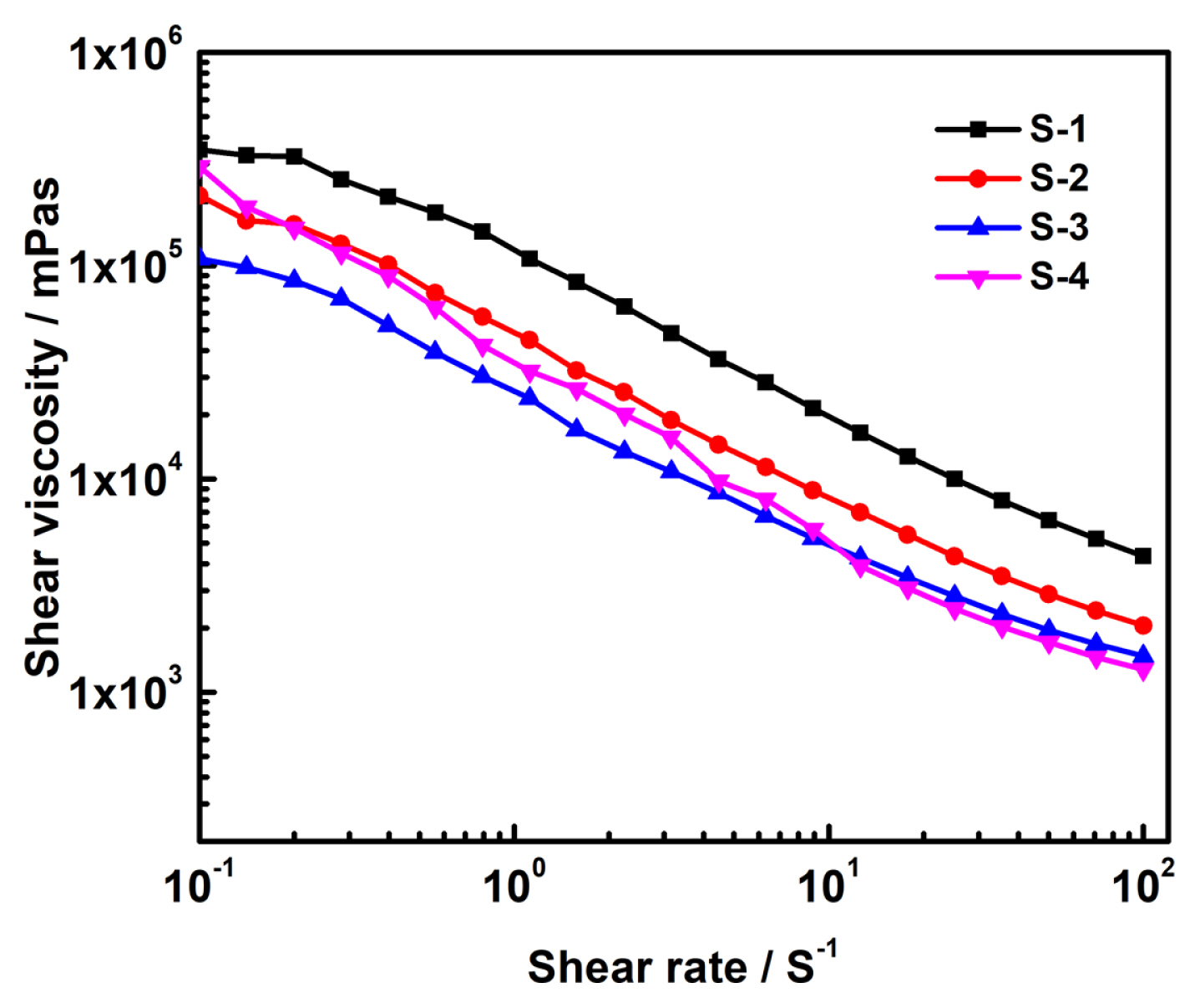
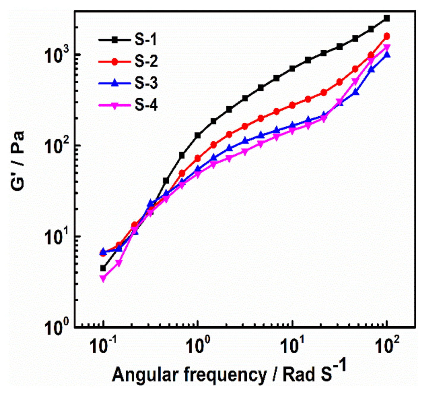
Fig. 2 shows the non-Newtonian fluid behaviour of the electrode slurries (S-1, S-2, S-3, and S-4) prepared by sequential addition of NMP solvent for homogeneous solution [15]. It is worth to note that the viscosity of the slurry decreases with increase of the shear rate which is clear evidence of thinning behaviour of the electrode [21,22]. A more uniform coating can be expected with the less viscous slurries at high shear rates and the S-3 and S-4 are showing less viscosity at a higher shear rate than the S-1 and S-2. Fig. S1 shows the viscoelastic representation of the relationship between the viscous (liquid like) and elastic (solid like) behaviour of the electrode material. The desired viscoelasticity contained slurry samples have the better dispersion and stability. It is observed that the S-1 sample shows the storage modulus (GŌĆ▓) is larger than the loss modulus (GŌĆ│) which indicates the solid like gel behaviour [23]. In the multi-mode mixing sequence, (S-2 to S-4) the slurries are showing liquid like behaviour which gains higher GŌĆ│ than that of the GŌĆ▓, indicates that the nature of the slurry viscous is low. The low dependence of GŌĆ▓ to the frequency was observed in the S-3 and S-4 samples as compared to S-1 and S-2 (Fig. 3). The lower frequency dependence on the GŌĆ▓ was due to the formation of the bridging flocculation between the binder and cathode active particles and maintains an optimal interactive distance between the cathode particles and the binder which appears to be an optimal viscoelastic nature of the slurry. It indicates that the particles are well dispersed and stabilized, usually have relatively smaller GŌĆ▓ as compared to the GŌĆ│ and shows a wider linear viscoelastic regime [10,21]. The viscoelastic representation of relationship between viscous (liquid) and elastic (solid) behaviour of electrode material shown in supplementary section.
3.2 Scanning electron microscope
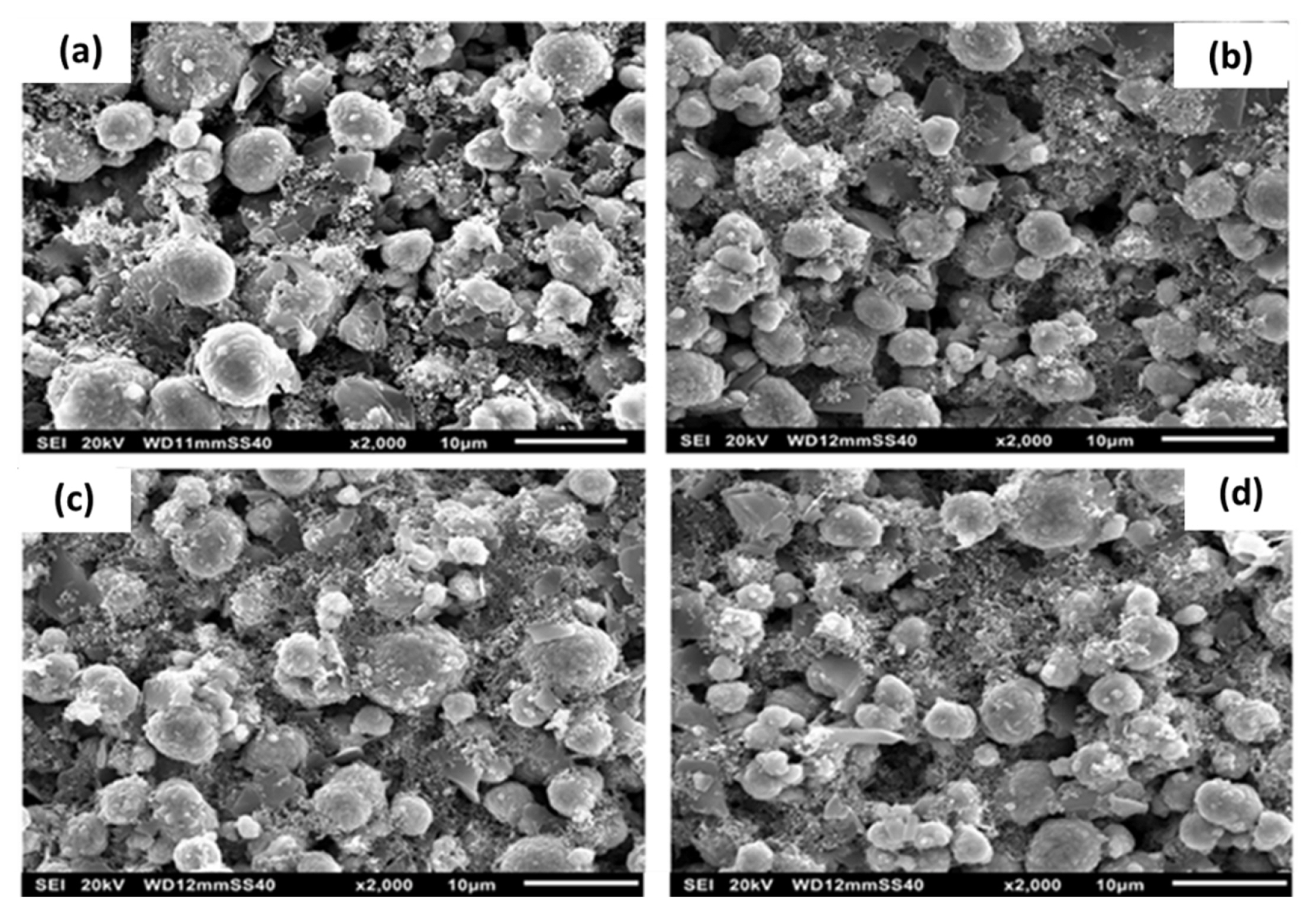
Well dispersed and uniform distribution of the conducting carbon particle on the active materials in presence of the binder in the Li-ion cells can be mapped by the SEM. The Fig. 4 shows the SEM images of the cathode electrode with different addition of the NMP solvent to the mixture of NCA, conductive carbon and graphite. Fig. 4(a) shows that the sample S-1, the mixing of the conductive carbon materials (AB and graphite) in the cathode mixture is not well dispersed. The binder was observed on the surface of the cathode particles indicating that there is no uniform network formation [20]. The dispersion of the conductive additive increases with an increase of the mixing process steps as observed in the S-3 (Fig. 4(c)) and S-4 (Fig. 4(d)) samples that is the dispersion of the conductive particles on the surface of the active cathode particles. S-3 sample in Fig. 4(c) shows the uniform wrapping up on the cathode active particle with the conductive additive and binder. Further, by increasing the mixing process steps, the interaction between the binder and the conductive carbon can disturb and solid particles come together via the van der Waals forces and aggregate together. Hence, the amount of solvent utility will reduce and the slurry starts attaining the sol in nature. The GŌĆ│>GŌĆ▓ modulus conforms the sol in nature and it further extends with increasing to the S-4 sample.
After coated samples, calendaring is most important part and in a biaxial way, because the electrode densification used for increase volumetric energy density of the cells and also important in improves the electrical contact, adhesiveness and capacity retention. Here, the coated electrode applied 0.5 Tons of pressure in the first pass and it reduces the thickness into 5% from its initial electrode thickness. After that, we applied 4 Tons of pressure for more densification of electrode to reduce upto 27ŌĆō28% of its thickness. Fig. 5 shows that the compaction of electrode with reduce in porosity of the electrode. The particle agglomeration is less due void obtained more in S-1 shown in Fig. 5(a). The better agglomeration and decreased in porosity of S-2 shown in Fig. 5(b). Fig. 5(c) shows the uniform wrapping up on the cathode active particle with the conductive additive, binder, reduces the porosity and also obtained uniformity of the electrode for S-3. The S-4, further by increasing step of solvent it starts to affect the agglomeration and the materials turns into sol nature. The stability of slurry was affected more steps to add solvent and bridging flocculation of cathode and binder materials shown in Fig. 5(d).
3.3 Peel strength
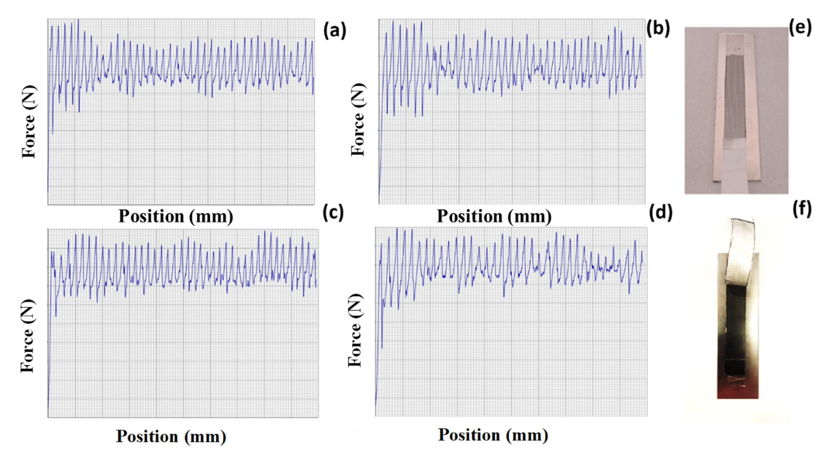
The mechanical strength of the electrodes with different step addition of NMP was studied by peel strength. A 25-mm-wide and 150-mm-long cathode with changing binder percentage was connected to 3 M adhesive tape, and a highly accurate micromechanical test instrument was used to quantify the cathode sample peel strength. The electrode pasted on adhesive tape was peeled off at an angle of 180 degrees while moving at a constant speed of 20 mm/min. Force/displacement graphs were created by continually measuring the applied load [24]. Fig. 6(aŌĆōd) shows the peel strength of the electrode (S-1 to S-4). Here, peel extension is the displacement of the upper grasp, and peel strength is calculated by dividing the force by the sample width. Using data with peel extension ranging from 25 mm to 150 mm, the median and standard deviation of the peel strength were determined. The results are given in Table 1. Fig. 6(a) and (b) shows the high voids present on the surface of the electrode. For Fig. 6(c), uniform peel range was obtained due to less voids on the electrode. As it is same like S-4 shows higher in voids because of converting into sol nature of the electrode composite. Fig. 6(e) and (f) are before and after peel strength study of the electrode, respectively.
3.4 Electrochemical studies
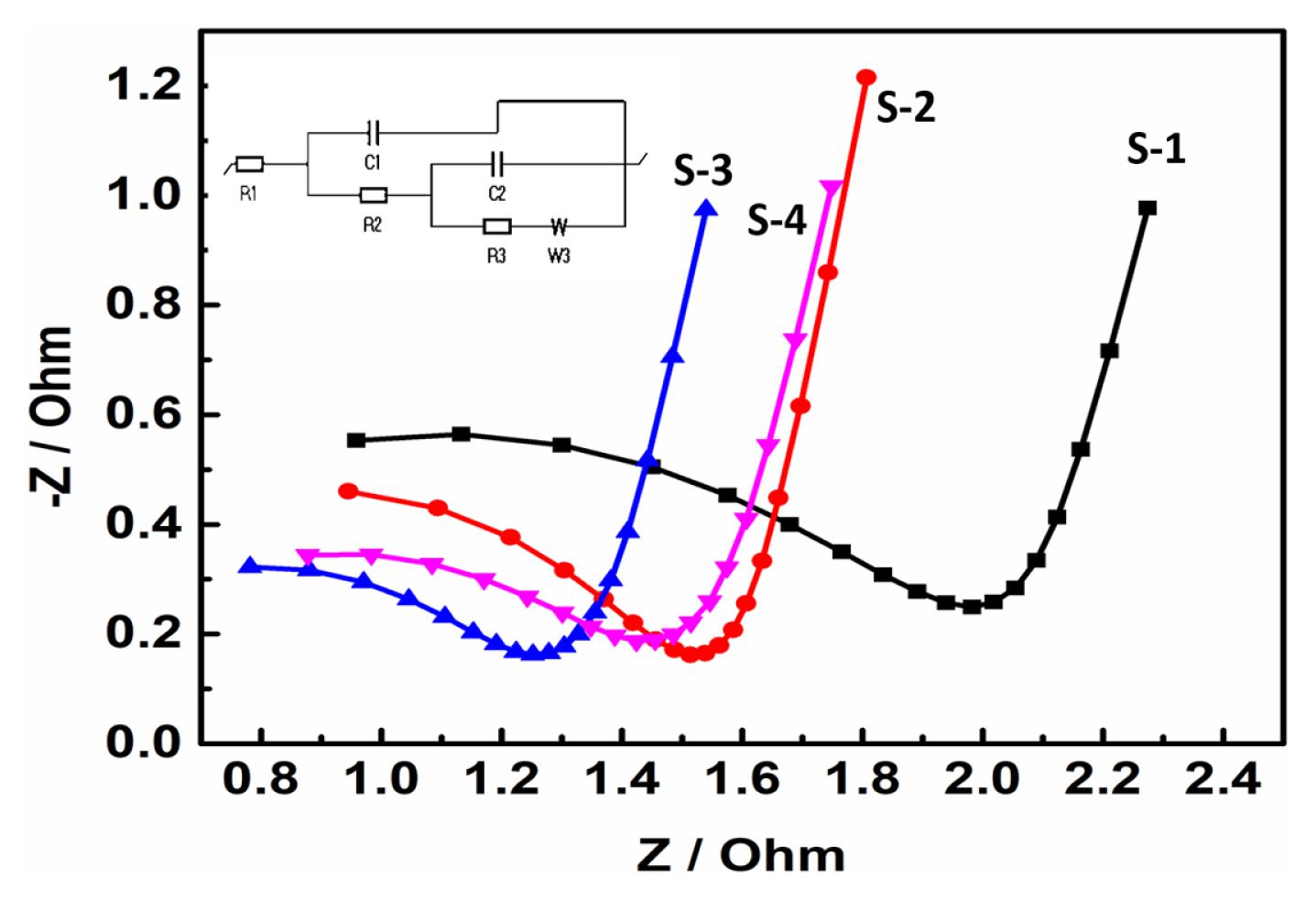
EIS studies were carried out on the pouch cell to understand the electrode behaviour with sequential addition of solvents process in the cathode mixing method. The cells were prepared with different cathode electrode slurries (S-1 to S-4) and the EIS characteristics are presented in Fig. 7. The EIS spectra profile reveals that the S-1 to S-4 samples follow almost similar behaviour with the formation of semicircle at high frequency region followed by a slope in the low frequency (Fig. 7). The EIS characteristics represents the charge transfer resistance (Rct) and the Warburg impedance corresponding to Li-ion diffusion in the electrode. The Rct values of the S-3 and S-4 are lesser than the S-1 and S-2 Rct values. The low Rct value of the electrodes indicate that the S-3 electrode had better electronic conductivity as compared to other electrodes (S-1, S-2, and S-4). The EIS results further support the flocculation formation that is wrapping up of the NCA cathode particle with conductive additives and binder which improves the stability and conductivity of the electrode. The low Rct of the electrodes indicate that the S-3 electrode had better electronic conductivity as compared to other electrodes (S-1, S-2, and S-4). Our electrode is fitted with R1+C1/(R2+C2/R3+W3) circuit.
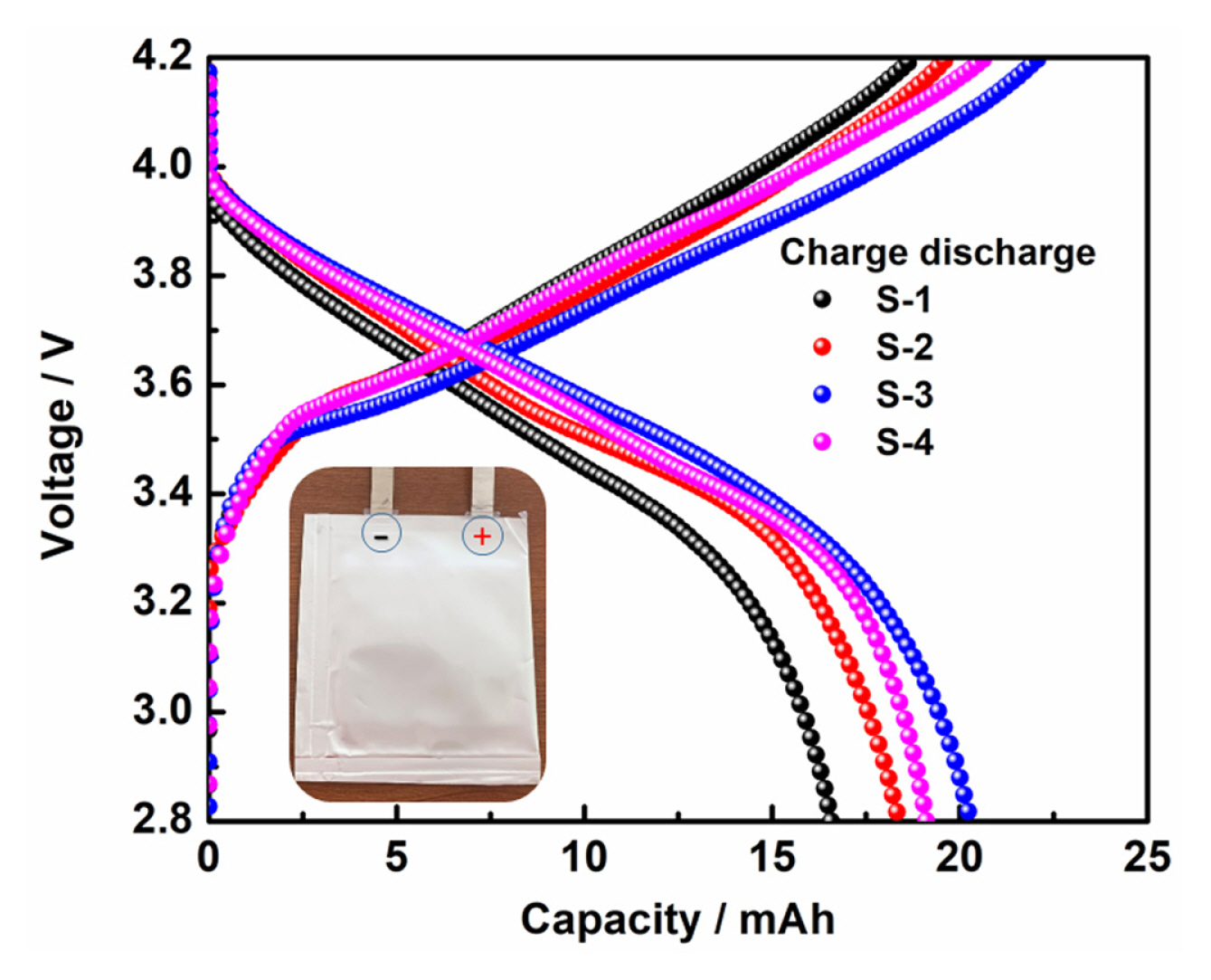
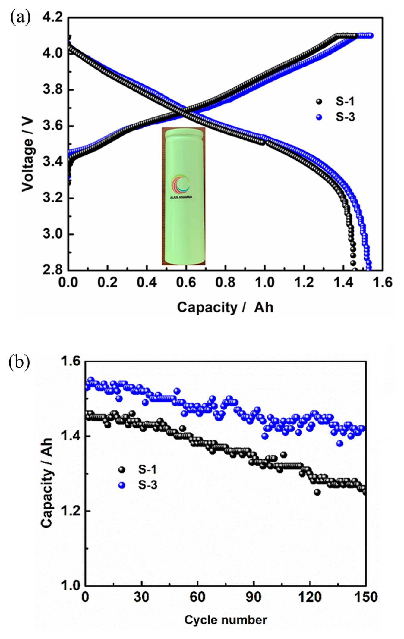
Fig. 8 and 9 shows the electrical performance of the cells was carried on pouch and cylindrical type of configuration with capacity of cell 20 and 1500 mAh, respectively, using layered NCA cathode with respective compositions as given in experimental section (S-1 to S-4). The graphite was used as negative electrode and the N/P capacity ratio maintained 1.15. The galvanostatic tests were carried out in the potential window of 2.8 V to 4.1 V at 0.2 C rate at room temperature for pouch cell and all subjected to three formation charge-discharge cycles at C/10 current rate and processed for degassing after completion of formation cycling. Fig. 8 shows the charge-discharge profile for the first cycle of pouch cells after formation. The NCA (S-1 to S-4) composition showed the higher cell charge/discharge capacity of 16.52, 18.31, 20.24, 18.75 mAh. The observed high columbic efficiency with high discharge capacity for the NCA S-3. We studied using commercial 18650 cylindrical cells are fabricated with the composition on high and low cycling efficient NCA cathodes S-1 and S-3, respectively. Fig. 9(a) showed the first charge-discharge profiles of 18650 cylindrical cells at 0.2 C rate charge and 0.5 C discharge rate between potential window of 4.1 and 2.8 V. The observed discharge capacities are 1.46 Ah and 1.53 Ah for the S-1 and S-3, respectively. The cyclic life behaviour of the S-1 and S-3 containing 18650 cylindrical cells to compare the capacity retention between the single step mixing electrode cylindrical cell and the high-performance mixing electrode cylindrical cell. The capacity of S-1 and S-3 cathode made cylindrical cells at 1.25 and 1.42 mAh for the capacity retention of 85.7 and 92.9%, respectively and Fig. 9(b) shows 150 cycles. This indicates that the three-step mixing (S-3) electrode show excellent high cycling performance.
4. Conclusions
The electrode slurry is critical in improving the electrode stability and better performance of the lab scale developed Li-ion cells. The Ni-rich cathode electrode was prepared with different level of mixing of NMP solvent to the cathode active material mixture. The rheology properties of the slurry were evaluated and the formation of the bridging flocculation optimises the interactive distance between the active materials optimizes the interactive distance between the active particles, which leads to optimal viscoelastic nature of the slurry. The homogenous mixing of dry powders and good dispersion of additives in the polymeric network structure helps to stabilize the electrode. The electrochemical performance of the Li-ion cells (pouch and cylindrical type) shows an improved performance in terms of capacity, capacity retention and cycle life relative to the various step process of mixing solvent with active material. The sequence of addition of NMP solvent/binder solution to the cathode active material have beneficial effect on the cell performance is due to the contribution of lower internal resistance of cell as evidence by EIS analysis in comparison to the single step process. The present results on the sequential addition of solvent to the cathode electrodes mixture may be further extended to optimize the electrode slurry processes for scaling up to large scale production.