1. Introduction
At present, the main energy source is petroleum fuel, which is widely used to meet the needs of all social strata. However, limited resources are not enough to support the progress of the industry in the future. At this time, finding alternative energy has become the top priority in today's society. Under such urgent conditions, the development of economical energy storage system and equipment is a general trend of the current social development [1]. In order to solve these problems, researchers have begun to develop energy devices, such as batteries, fuel cells, electrochemical supercapacitor [2,3]. The supercapacitor is mainly composed of high-performance electrode material, electrolytes, porous membranes, fluid collection and outer packaging materials. The supercapacitor is divided into three categories by energy storage mechanism and the difference in active materials [4], electrochemical capacitor [5], electric double layer supercapacitor [6], and hybrid supercapacitor [7]. The supercapacitor has many excellent electrochemical performances, as excellent charge and discharge efficiency, high efficiency capacitance retention rate, and stable cycle performance, etc. These advantages play a vital role in the practical application of supercapacitor.
The electrode material of electric double layer supercapacitor is high surface area carbon-based active materials. During operation, the electrode material not produces faraday reaction, the explosion hazard of supercapacitor is avoided at cycle charge and discharge period [8]. The energy storage mechanism of electric double layer supercapacitor is electrostatic interaction between the ions on the contact area of the active electrode material and the electrolyte [9]. The process only takes a few seconds, the performance depends on the activity and kinetic characteristics of the electrochemical electrode. Therefore, electrode material must have high specific surface area, large porosity and uniform pore distribution [10]. The electrode material of is electrochemical capacitor is transition metal oxides with pseudo capacitance and conducting polymer [11]. The energy storage mechanism of electrochemical capacitor is the rapid reversible faraday REDOX reaction occurs to or near the surface of the electrode material [12]. Compared with the electric double layer supercapacitor, the electrochemical capacitor has high capacitance and energy density, however, the power density, cycle performance, and rate capability are poor [13]. Hybrid ultracapacitor has the characteristics of electric double layer supercapacitor and electrochemical capacitor, and the energy density and power density are between the two capacitors [14].
The electrochemical performance of the supercapacitor strongly relies upon the type, properties and the surface structure of the electrode material, which should have a high surface area, great electrical conductivity and high chemical stability [15]. At present, the electrode materials of the supercapacitors are mainly electrode materials three categories: carbon materials (graphene [16], activated carbon [17], and Carbon nanotubes [18]), conducting polymer (Poly benzene [19], polypyrrole [20], and polyaniline [21]), and transition metal oxide (RuO2 [22], IrO2 [23], MnO2 [24,25], NiO [26], and Co2O3 [27,28]). Among many transition metal oxides, Co2O3, NiO, and V2O5 have relatively narrow potential windows and low energy density [22ŌĆō29]. The MnO2 as pseudocapacitive electrode material is extensively researched due to higher theoretical ratio of capacitance, low cost and abundant resources, etc [24,25]. However, manganese dioxide still has many drawbacks: (1) The actual specific capacitance is lower than the theoretical specific capacitance; (2) The poor conductivity seriously affects the ion transfer rate for charging and discharging; (3) Poor cycling stability, surface passivation or dissolution in the long cycling process affects the capacitance of the material. Therefore, the drawbacks could be solved by preparation of porous and high conductivity materials. The porous and laminated materials could shorten the diffusion path of ions and provide a large number of reactive sites [30]. The core-shell structure with MnO2 as outer layer degraded at long cycle process. At the reaction with electrolyte, the surface of electrode forms the insulating layer due to the Mn4+ moves towards the electrolyte, ions and protons are exited and embedded. The insulating layer is referred to as solid electrolyte interphase (SEI) [31]. The condition causes irreversible loss of material capacitance. The researchers propose to apply the polymer to a surface coating or substrate, the polypyrrole (PPy) is considered one of the most attractive polymers [32,33]. The PPy can not only reduce the resistance in the electrochemical reaction of charge transfer, but also prevent the passivation between the active substance and electrolyte [34]. More importantly, the electrode material is protected by PPy coating. This condition contributes to prevent SEI membrane ruptures during electrochemical process, to ensure the coulomb efficiency and long-term stability of the cycle [35]. The combination of the PPy layer and the oxide is an effective method to improve the electrochemical performance, such as SnO2/PPy [36], Fe2O3@PPy [37], and MnO2@PPy [38].
To improve the electrochemical performance of MnO2, we synthesize Co3O4@MnO2@PPy composite electrode by using the Co3O4 nanowire and PPy as the core and shell, respectively. Through testing, we found that the ŌĆ£core-shell-shellŌĆØ structure makes use of synergistic effect [39ŌĆō42] to obviously promote the process of charge transfer, obtain higher capacitance, and improve the materialŌĆÖs multiplier ability and cycling stability. In addition, the application of electrodeposition to protect the PPy coating is conducive to stabilizing the SEI membrane and protecting the structural collapse of manganese dioxide during the long cycle.
2. Experimental
2.1 Co3O4 precursor synthesis
The Co3O4 precursor (the molar ratio of CoO and CH4N2O is 1:5) is synthesized by hydrothermal method. Firstly, the CoO and CH4N2O are dissolved in deionized water in quantities of 30 mL. Continuous agitation of the solution at room temperature is conducted until the solution becomes pink. Then, the pre-treated nickel foam is placed vertically into the PTFE reactor with hydro-thermal treatment at 160┬░C for 6 h in vacuum drying oven. When the reaction completed, the reactor is laid aside for 12 hours. The pre-treated nickel is washed several times in deionized water and dried at 80┬░C for 3 h on hot plate. Finally, the precursor is calcined at 350┬░C for 3 h in box-type furnace then the precursor is obtained.
2.2 Co3O4@MnO2 synthesis
First, the KMnO4 is dissolved in deionized water in quantities of 30 mL at the appropriate molar ratio, the solution is heated at 90┬░C for 15 min in water bath kettle, and continuous agitation of the solution at room temperature is conducted until the solution becomes purple. Then, the Co3O4 precursor is placed vertically into reactor and the solution is poured into reactor. Hydro-thermal treatment at 160┬░C for 6 h is carried out with reactor in vacuum drying oven. Finally, the Co3O4@MnO2 composite electrode is obtained after the pre-treated nickel is washed several times in deionized water and dried at 80┬░C for 3 h on hot plate.
2.3 Co3O4@MnO2@PPy synthesis
The PPy thin film is grew on Co3O4@MnO2 composite electrode surface by electrodeposition method. The electrodeposition process is carried out in three-electrode electrochemical station with Co3O4@MnO2 composite electrode as the working electrode, platinum plate as the opposite electrode, and Ag/AgCl as the reference electrode. Electrolyte for the PPy electro-deposition is synthesized by dissolving the appropriate molar ratio of PPy and KOH in deionized water in quantities of 20 mL. The Co3O4@MnO2@PPy composite electrode is synthesized at a voltage of 1.0 V for 600 s. Finally, the final sample is obtained after the Co3O4@MnO2@PPy composite electrode is washed several times in deionized water and anhydrous ethanol dried at 60┬░C for 2 h on hot plate.
2.4 Synthesis of asymmetric supercapacitor
2.4.1 Synthesis of negative electrode material
The nickel foam is washed by wash several times in deionized water and anhydrous ethanol, then the nickel is dried at 60┬░C for 12 h in vacuum drying oven. The negative electrode of asymmetric supercapacitor is prepared by mixing 90 wt% activated carbon and 10 wt% PTFE, followed by adding anhydrous ethanol until the slurry formed. The slurry is coated on nickel (1 cm2), the nickel si dried in hot plate at 60┬░C for 3 h and pressed under pressure of 15 MPa. Finally, the negative electrode materials of asymmetric supercapacitor is obtained.
2.4.2 Assembly of asymmetric supercapacitor
The PVA-KOH gel electrolyte is prepared by adding PVA (4 g) into solution of 2 M KOH (40 mL) in beaker and stirred with magnet stirrer at 90┬░C for 3 h to dissolve the PVA. The positive and negative electrode materials and diaphragm are immersed in PVA/ KOH gel electrolyte for 10 min, the positive and negative electrode materials are separated with the diaphragm, and the asymmetric supercapacitor is assembled sequentially with aluminum foil as the outer packing.
2.5 Materials characterization
The crystal structures of pure MnO2 (Tianjin Zhiyuan Chemical Reagent Co. LTD), Co3O4@MnO2, and Co3O4@MnO2@PPy are characterized by XRD with a CuK╬▒ (╬╗=0.15418 nm) radiation source (D/ max-2500, Japan). The surface morphologies of the samples are identified by FE-SEM (Sigma-500, Germany), and the structure and diffraction method are further identified and discussed by TEM (JEM-2100F, Japan). The surface composition of materials are marked and identified by XPS (250Xi, USA).
2.6 Electrochemical characterization
The electrochemical measurements for three kinds of samples are performed by electrochemical station (Ivium, Netherlands) in the three-electrode mode in 2 mol┬ĘLŌłÆ1 KOH aqueous solutions as electrolytes at room temperature. The electrochemical performance is carried out by cyclic voltammetry (CV), galvanostatic charge-discharge (GCD) and electro-chemical impedance spectroscopy (EIS) measurements.
The electrochemical performance of asymmetric supercapacitors is tested by double-electrode system of electrochemical workstation (CHI 660E), and by cyclic voltammetry, galvanostatic charge-discharge, and long-cycle tests are performed, respectively. The battery cycle stability is tested by Xinwei battery test system BTS8.
3. Results and Discussion
3.1 Morphology and structure analyse
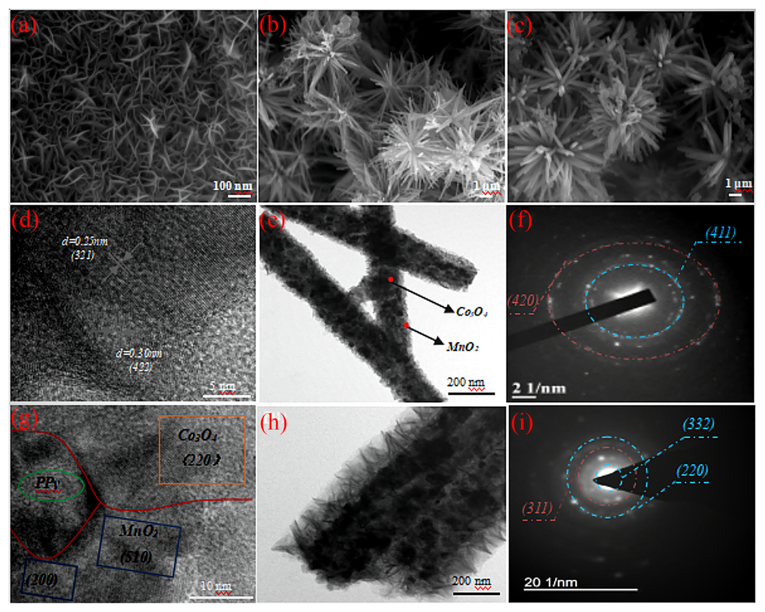
The particle morphology structure of pure MnO2, Co3O4@MnO2, and Co3O4@MnO2@PPy are displayed in Fig. 1. The pure MnO2 displayed nanosheet structure with the staggered lap is in a multi-channel state (Fig. 1(a)). The morphology of Co3O4@MnO2 forms rod structure is influenced by substrate shape, and resulting in the formation of porous pattern core-shell structure with radiation-outward growth at the center (Fig. 1(b)). The Co3O4@MnO2@PPy is obtained after the PPy is deposited on the surface of Co3O4@MnO2 (Fig. 1(c)). Compared with the Co3O4@MnO2, the Co3O4@MnO2@PPy has a larger rod diameter, and it can be proved from the side that the PPy layer is successfully deposited on the surface of Co3O4@MnO2. The particle size and morphology of Co3O4@MnO2 are displayed in Fig. 1(d, e). The interplanar distance of 0.25 nm correspond to (321) of ╬▒-MnO2, and the interplanar spacing of 0.3 nm correspond to (422) of Co3O4. The obvious core-shell boundary is observed in the porous pattern structure of Co3O4@MnO2, the low conductivity of MnO2 is improved with highly conductive material Co3O4 as the ŌĆ£coreŌĆØ and MnO2 as the ŌĆ£core-shellŌĆØ. The selection diffraction pattern of Co3O4@MnO2 in Fig. 1(f), the polycrystalline structure of Co3O4@MnO2 is observed by two obvious distinct diffraction rings with corresponding (411) of ╬▒-MnO2 and (420) of Co3O4. The high resolution TEM diagram of Co3O4@MnO2@PPy is displayed in Fig. 1(g). The interplanar spacing of 0.18 nm correspond to (220) of Co3O4, the interplanar spacing of 0.26 nm and 0.103 nm correspond to (510) and (220) of Co3O4. The TEM diagram of Co3O4@MnO2@PPy in Fig. 1(i). The successful deposition of PPy is improved by the nanorods are 261 nanometers in diameter (including the outermost shell), which is 1.7 times the diameter of the Co3O4@MnO2 nanorods. The selection diffraction test of Co3O4@MnO2@PPy is displayed in Fig. 1(i). Three main diffraction rings are corresponded to (320) and (220) of ╬▒-MnO2, and (311) of Co3O4, respectively. The polycrystalline structures of Co3O4@MnO2 and Co3O4@MnO2@PPy are improved by selection diffraction. The PPy thin film grows on the surface of the porous pattern structure Co3O4@MnO2 composite electrode, the condition greatly facilitates the diffusion of electrolyte ions in electrode materials, improves the utilization rate of active sites, resulting in the material has excellent electrochemical performance.
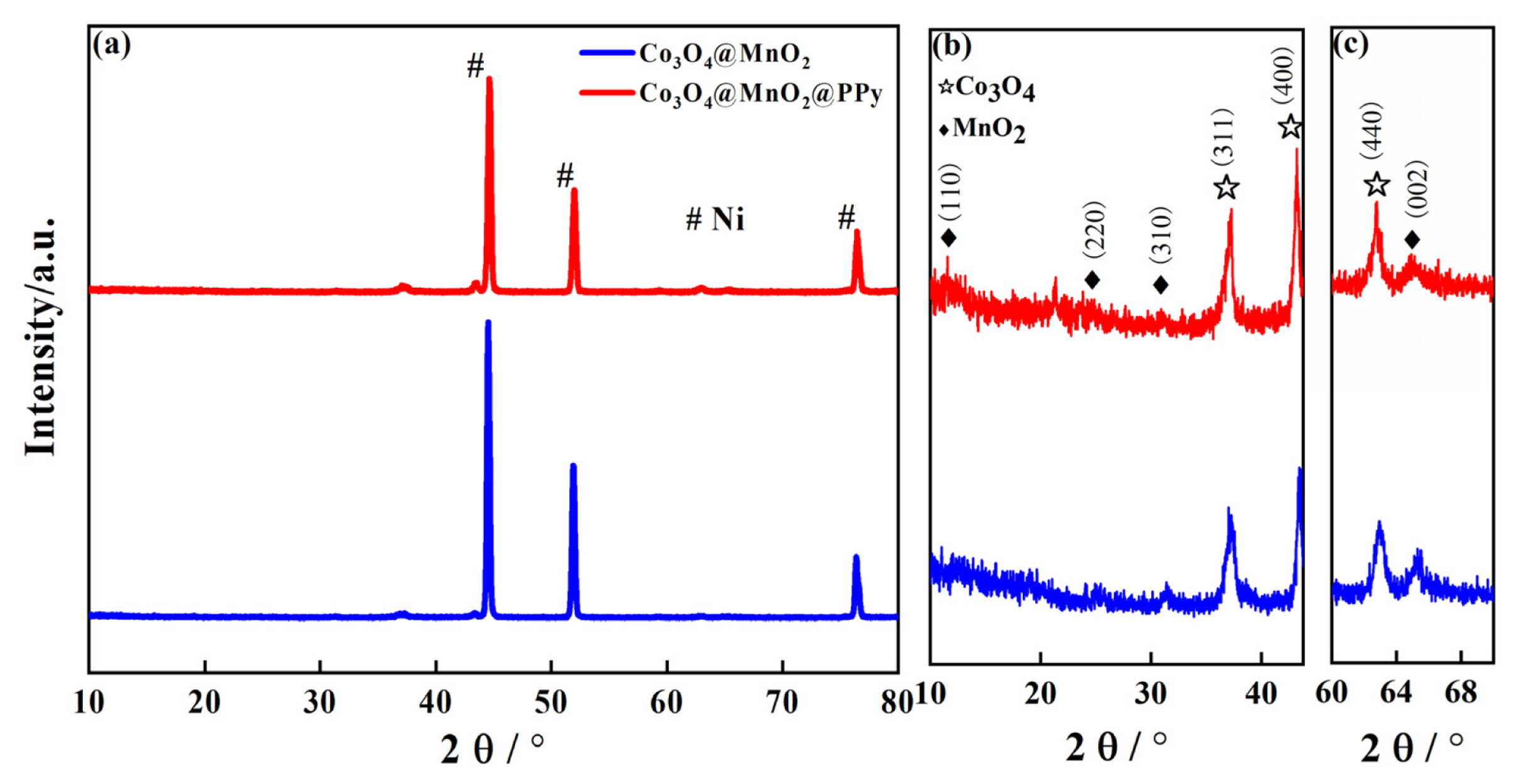
The crystalline structures of Co3O4@MnO2, and Co3O4@MnO2@PPy cathode materials characterization are displayed by XRD in Fig. 2. The crystalline structures of Co3O4@MnO2, Co3O4@MnO2@PPy, and three distinct peaks are Ni basal peak in Fig. 2(a). The enlarge figure of Co3O4@MnO2, and Co3O4@MnO2@PPy at 10┬░-43.8┬░ and 60┬░-70┬░ in Fig. 2(b, c). As presented in Fig. 2(b, c), the coexistence phenomenon of ╬▒-MnO2 (JCPDS 44-0141, denote as ŌÖ”) and Co3O4 (JCPDS 42-1467, denote as Ōŗå). It can be seen that the diffraction peak of all Co3O4@MnO2@PPy is basically the same as the diffraction peak of the Co3O4@MnO2, which proves that there is the N in-situ polymerizates on the Co3O4@MnO2, and the structure is amorphous. Additionally, the crystallinity of Co3O4 is improved by PPy, the content of Co3O4 is much higher than MnO2, and the electrochemical performance of Co3O4@ MnO2@PPy is improved due to PPy with high conductivity has excellent electrical conductivity.
3.2 Chemical valence analysis
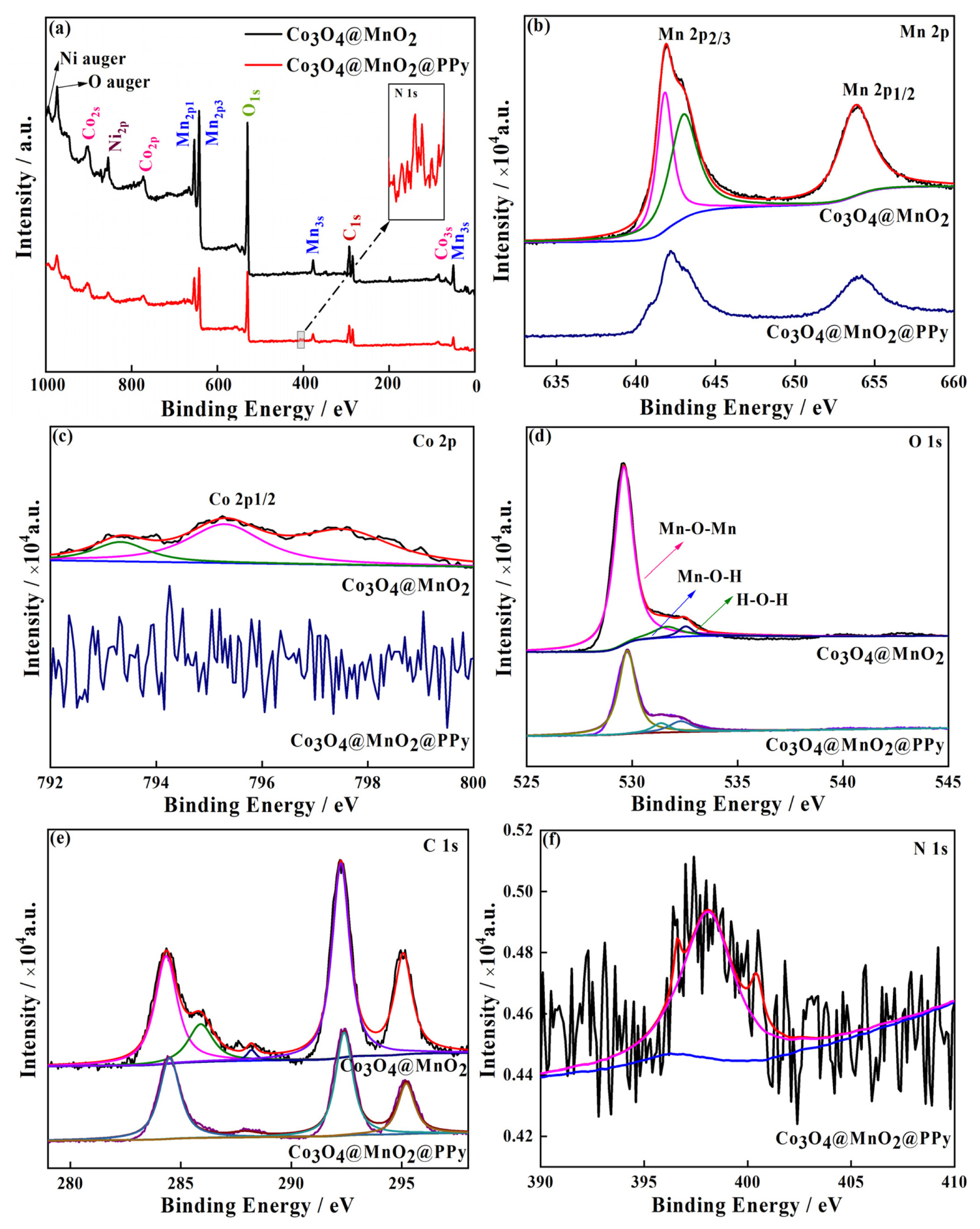
The chemical composition of Co3O4@MnO2 and Co3O4@MnO2@PPy are tested and researched by X-ray photoelectron spectroscopy (XPS) in Fig. 3, MnO2 sample is not discussed. The C, O, Ni, Mn, Co, and N elements are observed in Co3O4@MnO2 cathode material, among them, the Ni element is provided by foamed nickel. Moreover, the N element derived from highly conductive PPy, and compared with the Co3O4@MnO2, the intensity of each element of Co3O4@MnO2@PPy declined. The high-resolution measurement area of two samples in Mn 2p are displayed in Fig. 3(b), three peaks at 641.9, 643.0, and 653.9 eV. Furthermore, the Mn 2p XPS resulted for corresponding to Mn 2p1/2 and Mn 2p3/2, respectively, with the spin energy separation of approximately 12.0 eV. Demonstrating that Mn element is predominant in the whole material[42]. The three weaker Co 2P1/2 peaks at Co3O4@MnO2, because the Co peak is weakened for MnO2 on the surface of Co3O4, Co peak in Co3O4@MnO2@PPy is messy, demonstrating that the PPy grows on the surface of Co3O4@MnO2@PPy ((Fig. 3(c)). The three peaks on behalf of Mn-O-Mn, Mn-O-H, and H-O-H, respectively, at 529.6, 531.7, and 532.5 eV are measured in O 1s spectra in Fig. 3(d). Compared with the binary core-shell structure Co3O4@MnO2, the content of Mn-O-Mn in ternary core-shell structure Co3O4@MnO2@PPy is significantly decreased, which is mainly attributed to the existence of oxygen vacancy. In addition, as shown in Fig. 3(e) the C 1s spectra can be deconvoluted into five individual peaks, and the three main peaks at 284.3, 292.2, and 295.2 eV are consistent with Co3O4@MnO2@PPy. Only one peak at 397.8 eV from N bonds in PPy is existed in N 1s spectra in Fig. 3(f). Therefore, these results also confirm that a lot of PPy is deposited on the surface of Co3O4@MnO2 to form a hybrid hierarchical network composes of a lot of cross-sectional nanometers. Such a hybrid architecture, combines with highly conductive active materials, is more conducive to the electrochemical performance improvement brought by three-dimensional synergistic effect.
3.3 Electrochemical properties
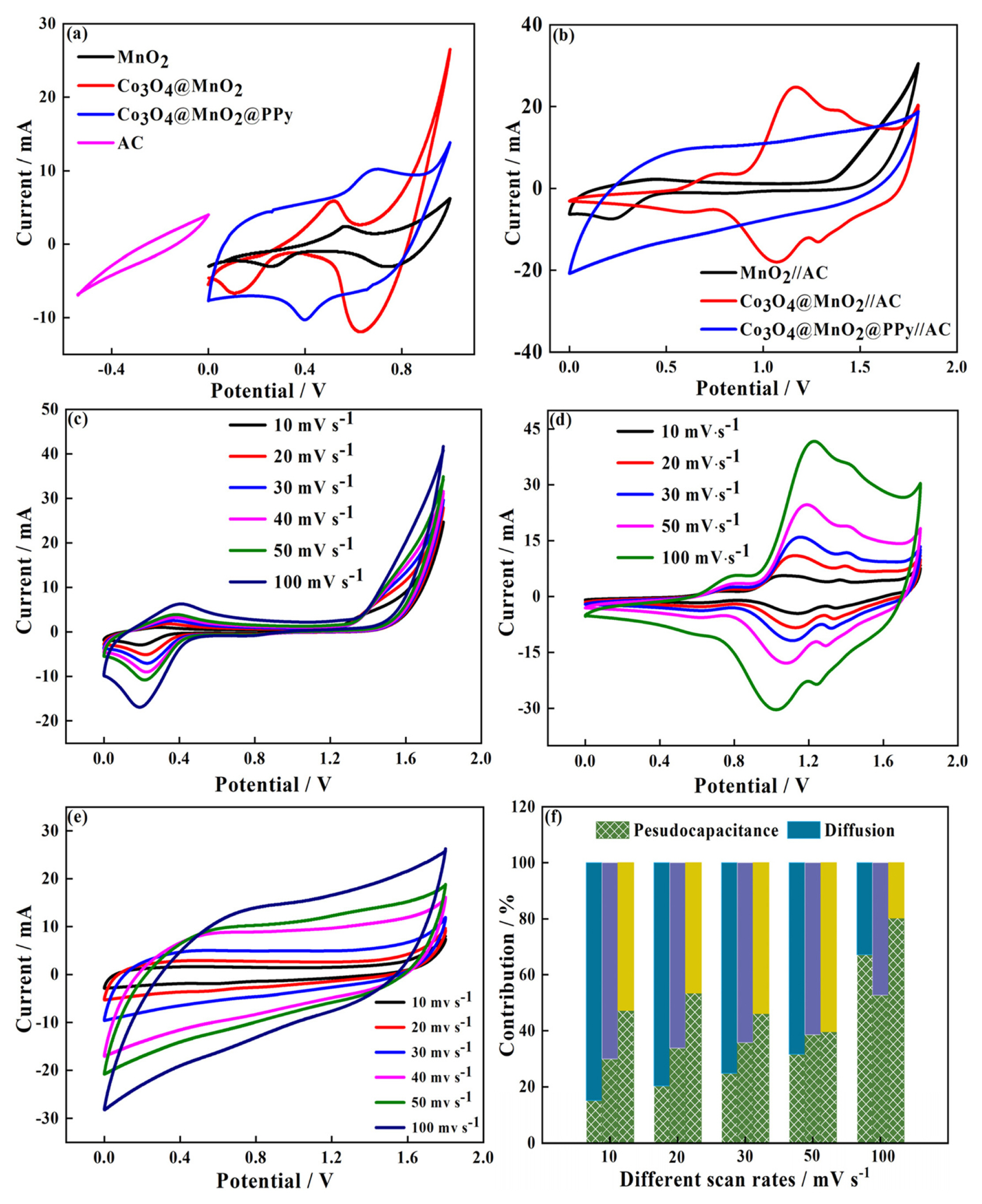
The electrochemical performance of pure MnO2, Co3O4@MnO2, and Co3O4@MnO2@PPy is displayed in Fig. 4. Three positive electrode materials exhibit two distinct plateaus, the pseudo capacitance and excellent reversibility of three materials is proved in Fig. 4(a), and Co3O4@MnO2@PPy has the largest electrical capacity of three materials. The capacitance contribution of three positive electrode materials, and the excellent electrochemical performance of Co3O4@MnO2@PPy is proved by pseudo capacitance contribution percent of 68% (Fig. 4(b)). The specific capacities of MnO2, Co3O4@MnO2, and Co3O4@MnO2@PPy are obtained from Fig. 4(c), which are 220, 449, and 977 F gŌłÆ1 at 1 A gŌłÆ1, respectively. As presented in Fig. 4 (d), the cycle process of MnO2 presents downtrend, the cycle retention rate is up to 82% after 400 cycles. The cycle process of Co3O4@MnO2 keeps smooth, the cycle retention rate is up to 99% after 400 cycles. The cycle process of Co3O4@MnO2@PPy presents unstable rising state in 135 cycles, the cycle retention rate is up to 105% after 400 cycles, the increase of the capacity retention rate confirms that the effective ion insertion/exfoliation occurred in the lattice. Compared with pure MnO2, the materials with layered porous pattern core-shell structure can storage high electrochemical energy, and reduced the migration path of electrolyte ions. To explore the electrochemical performance of Co3O4@MnO2@PPy, the internal resistance of the material is analyzed by ac impedance in Fig. 4(e, f). Compared with the Co3O4@MnO2, the Co3O4@MnO2@PPy has smaller charge transfer resistance and Warburg coefficient. It is proved that the preparation of Co3O4@MnO2@PPy with core-shell structure by electrodeposition method can improve electrochemical performance as a positive electrode material of supercapacitor.
3.4 Electrochemical characterization of the asymmetric supercapacitors
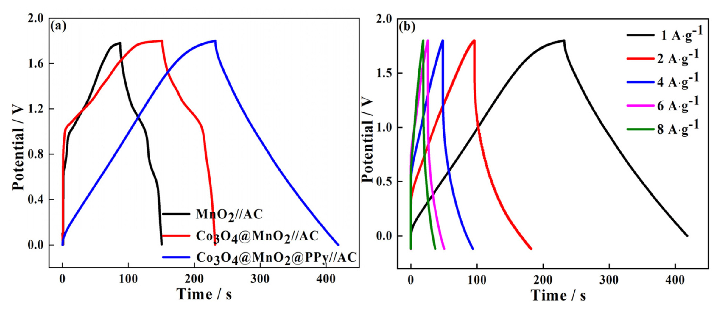
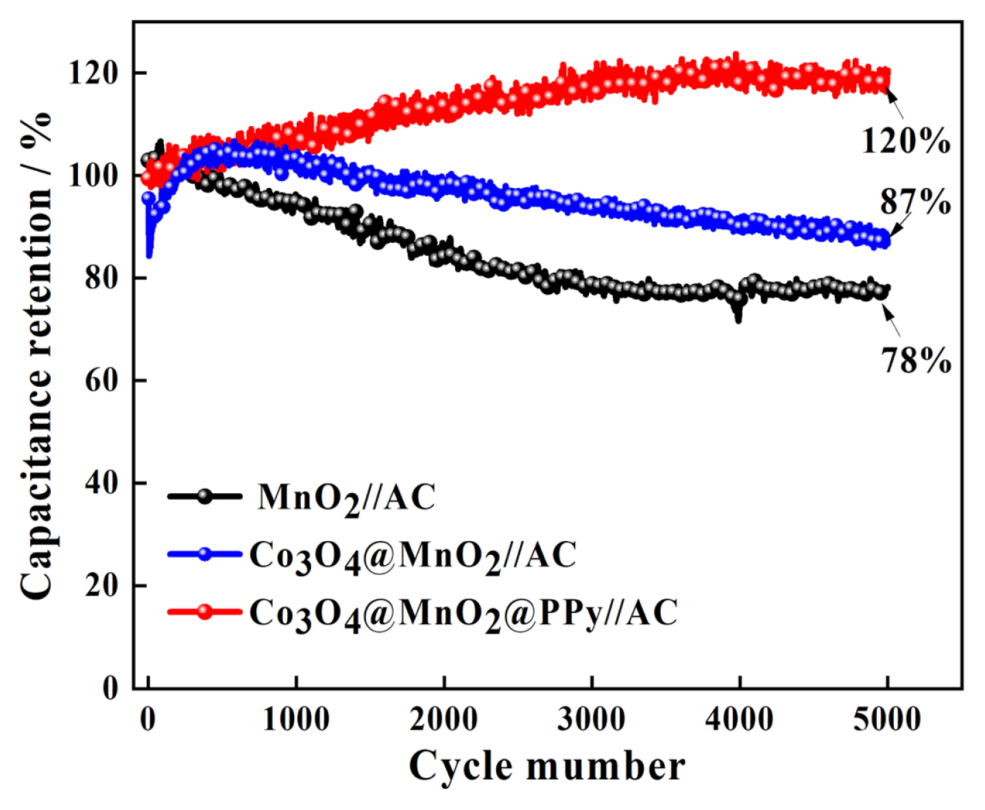
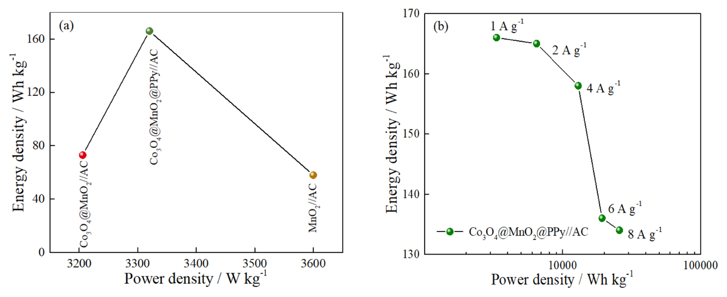
To explore the electrochemical performance of pure MnO2, Co3O4@MnO2, Co3O4@MnO2@PPy, and AC electrode for practical applications, the prepared materials are used as positive electrode materials for asymmetric supercapacitors, respectively, and activated carbon (AC) is used as negative electrode materials. The CV measurements are performed in the two-electrode mode (Fig. 5). The CV of pure MnO2, Co3O4@MnO2, and Co3O4@MnO2@PPy, at 10 mV sŌłÆ1 in Fig. 5(a). The CV curves displayed good capacitive behavior with symmetrical rectangular shapes. This indicates that Co3O4@MnO2@PPy has excellent reversibility and capacitance. The AC is activated carbon material, which is a typical double-layer material, the CV curve presented fusiformis. This finding indicates that the capacitive contribution of AC is less than anode material, and the positive electrode material determines the performance of the supercapacitor. The CV of MnO2//AC, Co3O4@MnO2//AC, and Co3O4@MnO2@PPy//AC at 10 mV sŌłÆ1 in Fig. 5(b). The CV curves of MnO2//AC, Co3O4@MnO2//AC occur obvious distortion high at a high cell voltage window of 0ŌĆō1.8 V. The CV curve of Co3O4@MnO2@PPy//AC has the biggest area and minimum distortion. It explains that ternary core-shell structure has better electrochemical performance. The CV curve shape of the three electrodes remain relatively unchanged at 10 to 100 mV sŌłÆ1, it can explain the electrodes has excellent stability (Fig. 5(c, d, e)). The diffusion capacitance of the three electrodes at different scanning speeds in Fig. 5(f). The capacitive contribution of MnO2//AC, Co3O4@MnO2//AC, and Co3O4@MnO2@PPy//AC increase from 26% to 75%, 30% to 52%, and 47% to 80% at 10, 20, 30, 50, and 100 mV sŌłÆ1, respectively. The capacitive contribution of the three electrodes increase with the increase of scanning speed, and the ternary core-shell structure always maintained the best capacitive performance. According to the above CV test, compared with the MnO2 / /AC and Co3O4@MnO2//AC, Co3O4@MnO2@PPy//AC have better capacitance performance. To prove the point, the three electrodes are charged and discharged with constant current (Fig. 6). The GCD curve of the three electrodes at 1 A gŌłÆ1 between 0 and 1.8 V in Fig. 6(a). The charging-discharge curves of the three electrodes are almost symmetrical, indicating their excellent electrochemical reversibility and coulomb efficiency. The specific capacitance of the three asymmetric supercapacitors is 35.56, 45.56, and 102.78 F gŌłÆ1. The capacitance of Co3O4@MnO2@PPy//AC has 2.9-fold with MnO2//AC. The specific capacitance of Co3O4@MnO2@PPy//AC is 102.78, 102.22, 97.78, 83.33, and 84.44 F gŌłÆ1 at 1, 2, 4, 6, and 8 A gŌłÆ1, it shows excellent rate capability (Fig. 6(b)). The capacitance retention rate of MnO2//AC, Co3O4@MnO2//AC, and Co3O4@MnO2@PPy//AC at 15 mA cmŌłÆ2 for 5000 cycles in Fig. 7. As presented in Fig. 7, MnO2//AC and Co3O4@MnO2//AC have a rising trend and the capacitance retention rate drops to 78% and 87% after 5000 cycles, respectively. The Co3O4@MnO2@PPy//AC achieves an excellent cycling capability, the capacitance retention rate is up to 120% after 5000 cycles. This condition is due to add highly conductive PPy increases the active site of the material and improves the free embedding/de-embedding state of ions, the capacitance ratio of the material is improved by synergistic effect of ternary core-shell structure, and the electrical conductivity of materials is improved by fast electron conduction channel of porous flowery structure. As presented in Fig. 8(a), the energy density of MnO2//AC, Co3O4@MnO2//AC, and Co3O4@MnO2@PPy//AC are 58, 73, and 166 Wh kgŌłÆ1, respectively, and power density are 3.6, 3.2, 3.3 KW kgŌłÆ1. Compared with the MnO2//AC, the energy density of Co3O4@MnO2//AC increases by only 15 Wh kgŌłÆ1, the energy density of Co3O4@MnO2@PPy//AC increases by 108 Wh kgŌłÆ1, and the power density of Co3O4@MnO2@PPy//AC is significantly improved. As presented in Fig. 8(b), at different current densities, although the energy density of Co3O4@MnO2@PPy//AC is reduced, the power density increased from 3.3 to 25.7 kW kgŌłÆ1. Compared with the asymmetric MnO2 based supercapacitors reported by others, the Co3O4@MnO2@PPy/ /AC supercapacitors has obvious advantages, such as MnO2/PPy//AC (38.6 Wh kgŌłÆ1) [43], Co3O4@MnO2// MEGO (17.7 Wh kgŌłÆ1) [44], and MnO2/C//AC (30.2 Wh kgŌłÆ1) [45].
4. Conclusions
This study synthesizes supercapacitor anode materialCo3O4@ MnO2@PPy by hydrothermal and electrodeposition. The structure, morphology, chemical constitution, and electrochemical properties are analyzed and discussed by XRD, FE-SEM, TEM, XPS, electrochemical workstation, and Land battery tester. Compared with the Co3O4@MnO2, the Co3O4 @MnO2@PPy has smaller charge transfer resistance and warburg coefficient. The specific capacitance of Co3O4 @MnO2@PPy is 977 F gŌłÆ1 at 1 A gŌłÆ1, the capacitance retention rate of 105% after 400 cycles. The capacitive contribution of Co3O4@MnO2@PPy is 68%. As the supercapacitor, the specific capacitance of Co3O4@MnO2@ PPy//AC is 102.78, 102.22, 97.78, 83.33, and 84.44 F gŌłÆ1 at 1, 2, 4, 6, and 8 A gŌłÆ1. The capacitive contribution of Co3O4@MnO2@PPy//AC increase from 47% to 80% at 10, 20, 30, 50, and 100 mV sŌłÆ1. The capacitance retention rate of Co3O4@MnO2@PPy//AC is 120% after 5000 cycles at 15 mA cmŌłÆ2. The special structure of the porous pattern Co3O4@MnO2@PPy anode material is conducive to a sufficient reaction with the electrolyte. The PPy nanosheet hybrid hierarchical network on the surface of Co3O4@MnO2, the hybrid architecture is combined with a highly conductive reactive material, this is more conducive to the electrochemical performance. The positive electrode material Co3O4@MnO2@PPy has the characteristics of high capacity and stable circulation, and has certain practical value.