


1. Introduction
The solid oxide fuel cells (SOFC) has been considered a promising electrochemical conversion device, due to its high efficiency, modularity, reliability, and environmental benignity [1-4]. The high temperature operation (700-900℃) of SOFCs allows various types of fuels to be utilized, including natural gas, biogas, coal derived syngas, and liquid hydrocarbon fuels, as well as pure H2. The fuel flexibilities can lower the operational costs of the SOFCs system by eliminating the need for high-grade purifying processes and for external fuel reforming systems, and allowing the direct use of economical fuels. Unfortunately, many economically available fuel sources contain sulfur species as impurity or additive, and their concentration can reach levels of over several hundreds of ppm in coal syngas and biogas derived from landfilled or sewage areas [5,6]. A mixture of Ni and yttria-stabilized zirconia (Ni/YSZ) has been used as the most popular anode material in SOFCs, due to its low cost, ease of fabrication, and high electrochemical property. However, the Ni-based cermet experiences critical degradation in levels of a few part per million (ppm) of H2S [7,8]. The H2S poisoning on Ni phase includes physical adsorption on the Ni surface, dissociative chemisorption of sulfur, and bulk nickel sulfide formation [9], depending on the H2S concentration, operation temperature, and cell current. Therefore, for direct utilization of such economically available fuels without strict pretreatment, alternative sulfur tolerable anodes should be developed, which would bring progress towards commercialization of SOFCs.
To overcome the sulfur poisoning problems of conventional Ni-based cermet anodes, several alternatives have been developed as anode materials, which lead to direct utilization of economically available fuels. Thiospinel sulfides, such as CuFe2S4, NiFe2S4, and CuCo2S4, have shown good electro-catalytic activity toward H2S oxidation [10,11]. Metal sulfides, including WS2, CoS2, and MoS2, were reported as alternative anode materials in H2S oxidation fuel cells to improve cell performance [12-14]. Doped and undoped cerium oxides have been reported as excellent candidates as sulfur tolerable components in metal cermet anodes, due to their reversible sulfur-sorbent property, as well as their good electro-catalytic property [15-17]. Perovskites with both ionic and electronic conductivity (MIEC) in reducing environment and at high temperature have been receiving increasing attention recently for their application as alternative SOFC anode or anode components, due to their superior properties for sulfur poisoning and carbon coking, compared to metal cermet [18-26]. In addition, the extended electrochemical reaction sites beyond triple phase boundary (TPB, electrolyte/electrode/ fuel) exhibited in the MIEC perovskites can decrease the interfacial polarization resistance. The MIEC perovskites also provide excellent compatibility with the dense electrolyte, and mechanical stability without thermal mismatch and/or structural failure during long-term operation. Although the reported alternative anodes or anode components have improved sulfur tolerance under SOFC operating condition, their low electrical conductivity and poor catalytic activity provide lower cell performance than the conventional Ni/YSZ anode-supported SOFCs.
In our previous research, we investigated the carbon deposition and sulfur tolerance of alternative anode materials, including Ni-based cermet, doped and undoped ceria, and perovskite [17,27-31]. In the present study, the electrochemical properties of Sr0.92Y0.08Ti1-yFeyO3-δ (SYTF) were investigated in fuels containing sulfur compound, to assess the feasibility of the oxide materials as alternative anodes. The Sr0.92Y0.08TiO3-δ (SYT), a promising alternative anode candidate, was modified by aliovalent B-site substitution by Fe3+ to improve the ionic conductivity for the electrochemical oxidation of adsorbed sulfur or sulfide. Using the modification, we aimed to improve the electrochemical properties of the SYTF anode, as well as enhance the sulfur tolerance.
2. Experimental
Sr0.92Y0.08Ti1-yFeyO3-δ (SYTF) powder was synthesized via the Pechini method with strontium nitrate (Sr(NO3)3·H2O, Aldrich), yttrium nitrate hexahydrate (Y(NO3)3·6H2O, Aldrich), titanium isopropoxide (Ti[OCH(CH3)2]4, Junsei), and iron nitrate nonahydrate (Fe(NO3)3·9H2O, Aldrich). The detailed synthesis method of SYTF has been reported elsewhere [30]. After calcination of the prepared solution-gel at 600℃ in air for 5 h, a single perovskite structure of SYTF was formed. The synthesized crystal structures were analyzed by X-ray diffractometry (XRD, Rigaku, RINT-5200). To investigate the electrical conductivity of the SYTF as alternative anode materials, the SYTF powder was pressed into cuboids at 7,600 kPa, and then sintered at 1,200℃ in air for 10 h. The electrical conductivity was measured via 4-probe direct current (DC) method with multi-meter device (Model 1000 series, Kithessly Co.). For electrochemical measurement, electrolyte supported SOFC was prepared by uniaxial dry-pressing of 8 mol% yttria-stabilized zirconia (8YSZ, Tosoh, Japan) powers. After sintering at 1,400℃ for 10 h, the 8YSZ electrolyte substrate was of 0.9 and 25.2 mm thickness and diameter, respectively. After cleaning the 8SYZ surface with ultrasonic device, the SYTF paste for anode was tape-casted on the 8YSZ electrolyte with the size of 0.69 cm2, and then sintered at 1,200℃ for 10 h in air. La0.85Sr0.15MnO3 (LSM) paste was coated as a cathode material on the 8YSZ electrolyte, and fired at 1,100℃. The anode microstructure was analyzed by scanning electron microscopy (FE-SEM, Hitach, S-4200, Japan).
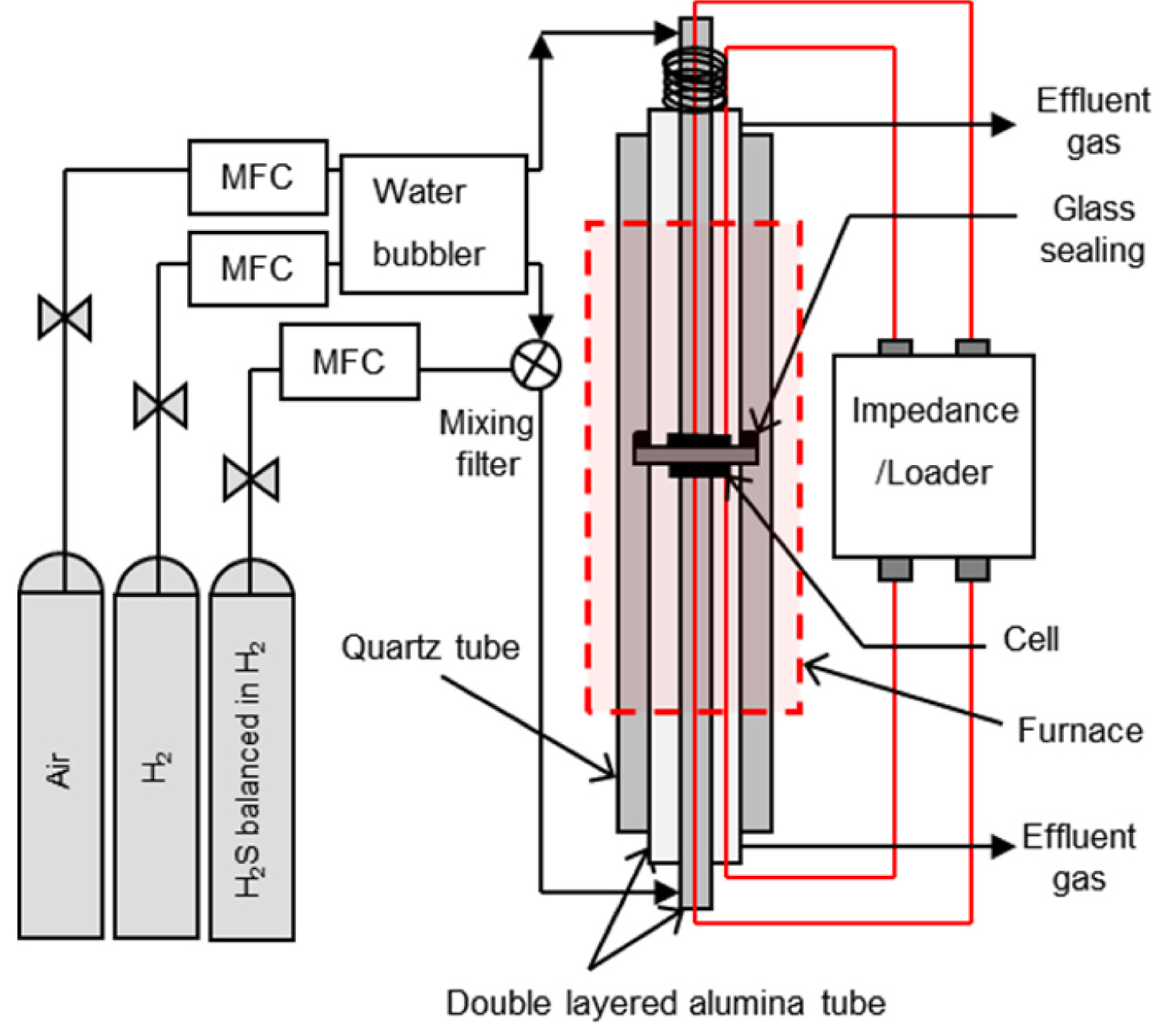
The electrochemical performance was investigated by mounting the electrolyte supported button cell between the double-layered alumina tubes, and sealing it with Pyrex glass on the dense electrolyte, as shown in Fig. 1. A perforated Pt plate (1 cm2 in area) and a Pt wire (0.5 mm in thickness) were used as current collectors. The H2S concentration was regulated with a mass flow controller (MFC) at 200 and 500 ppm of H2S balanced in H2 and pure H2, respectively. For example, 200 mL/min of 50 ppm H2S was obtained by mixing 50 mL/min of 200 ppm H2S and 150 mL/min of pure H2. Similarly, to obtain 200 mL/min of 200 ppm H2S, 80 mL/min of 500 ppm H2S was mixed with 120 mL/min of pure H2. The H2S gas was allowed to bypass the humidifier, and was mixed with pure H2 in a mixing filter, before fueling the reactor, to avoid the dissolution of H2S in water. The experiment was performed at H2S concentrations of 0 to 200 ppm. Either H2 or H2-H2S mixture was used as anode gas, and O2 was used as cathode gas. The electrochemical characteristics of the anodes were quantified using an impedance analysis device (SP-150, Biologic Science Instrument). The impedance spectra were recorded over the frequency range of 0.01 Hz - 1 MHz.
3. Results and Discussion
Fig. 2 shows the ex situ XRD patterns of SYTF powder calcined at varying temperature (400, 600, 800, 1,000, and 1,200℃) in air environment. No noticeable peaks were detected for the sample calcined at 400℃, where the perovskite crystalline structure was not formed. The perovskite phase of SYTF was observed at 600℃, and was prominent at higher temperature. Fig. 3(a) shows the XRD patterns of Sr0.92Y0.08Ti1-yFeyO3-δ (y = 0-0.5) powder sintered at 1,200℃. The amount of Fe as a B-site dopant in ABO3 perovskite was varied as 0 (SYT), 0.1 (SYTF0.1), 0.3 (SYTF0.3), and 0.5 (SYTF0.5) mole fraction. No noticeable peaks were detected in SYT, SYTF0.1, SYTF0.3, and SYTF0.5, other than strontium titanate based perovskite structure. All peaks shifted slightly to the right side with an increase in the amount of the Fe dopant as shown in Fig. 3(b). The different size of cations changes the tolerance factor of the SYTF perovskite structure, leading to the peak shift of the XRD patterns. Substitution of cations with different ionic radii into crystal structure changes strain of the crystal, referring to the tolerance factor of the SYTF perovskite. In addition, the strain caused by different concentration of Fe3+ in the SYTF would be directly and/or indirectly related to the effects of the sulfur tolerance and the cell performance. The tolerance factor in doped perovskite can commonly be described by:
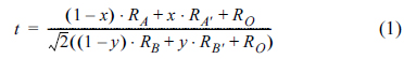
where, x and y are the mole fraction of dopant at the A and B sites, respectively; RA is the ionic radius of the A cation, and RA' is the ionic radius of the A-site dopant; RB is the ionic radius of the B cation, and RB, is the ionic radius of the B-site dopant; and RO is the ionic radius of oxygen anion. The tolerance factor for the SYT is 1.013, and it increases by increasing the amount of the B-site dopant for the SYTF0.1, SYTF0.3, and SYTF0.5 to 1.017, 1.023, and 1.030, respectively. The smaller radii of Fe3+ (0.55 Å for six-coordination) than Ti4+ (0.61 Å for six-coordination) causes the tolerance factor to be larger than 1, leading to the slight peak shift exhibited in the SYTF0.5. Although stable perovskite has a tolerance factor of (0.75-1), cubic perovskite structure still exhibits a tolerance factor of 1±0.05.
Fig. 2.
X-ray diffraction (XRD) patterns of SYTF0.5 calcined at varying temperature (400-1,200℃) for 10 h in air.

Fig. 3.
X-ray diffraction (XRD) patterns of Sr0.92Y0.08Ti1-yFeyO3-δ (y = 0-0.5) powder sintered at 1,200℃ in air.

Fig. 4 (a) shows the electrical conductivity of te SYT and SYTF0.5 sample in reducing (10% H2 balanced in N2), inert (N2), and oxidizing (Air) environment, at varying temperature (600-900℃). The electrical conductivity increased with elevating temperature, which corresponds to the conducting behavior of ceramic materials as a function of temperature. For the SYT sample, the electrical conductivities at 900℃ in H2, N2, and Air were 1.07, 0.39, and 0.08 S/cm, respectively. The electrical conductivities of the SYTF0.5 sample at 900℃ in H2, N2, and Air were 0.79, 0.13, and 0.06 S/cm, respectively. The electrical conductivity of doped perovskite is affected by the dopant size in both A-site and B-site. Because of the smaller radius of Y3+ (1.19 Å of ionic radius for twelve-coordination) than that of Sr2+ (1.44 Å of ionic radius for twelve-coordination), the Sr2+ in strontium titanate can be substituted by Y3+. This aliovalent cation substitution creates lattice defects to maintain the electrical neutrality of the crystals, and leads to n-type semiconductor behavior. For B-site substitution, Ti4+ can be substituted by Fe3+ to form Sr1-xYxTi1-yFeyO3-δ, because Fe3+ (0.55 Å of ionic radius for six-coordination) has very similar ionic radius to that of Ti4+ (0.61 Å of ionic radius for six-coordination). The mechanisms of formation of the electron pair in strontium vacancy as an n-type defect (1) and the oxygen vacancy (2) in Kröger–Vink notation are represented as:
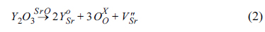
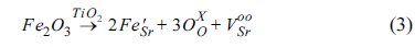
The two lattice sites of Sr2+ are substituted by Y3+ via mechanism (2), producing single strontium vacancy with two electrons ( ) per one mole of Y2O3, and it behaves as an n-type semiconductor. For the B-site, two lattice sites of Ti4+ may be substituted by Fe3+, producing single oxygen ion vacancy with two electron holes (
 ), where oxygen ions (O2-) can transfer. In addition, the reduction of TiO2 in doped SrTiO3 to TiO2-δ under reducing conditions produces additional oxygen ion vacancies, leading to the improvement of ionic conductivity. The electrical conductivity of SYTF0.5 exhibited lower than that of SYT, although both electronic conductivity and ionic conductivity were improved via mechanism (2) and mechanism (3). The two electrons in the strontium vacancies and the charged oxygen vacancies in the SYTF0.5 can be associated, leading to decrease of the electronic conductivity of the SYTF0.5. Because the magnitude of the electronic conductivity in MIEC is much higher compared to that of the ionic conductivity, the electrical conductivity of the SYTF0.5 was lower than that of the SYT. Fig. 4 (b) shows Arrhenius plots of the electrical conductivity corresponding to Fig. 4 (a), which can be described by:
) per one mole of Y2O3, and it behaves as an n-type semiconductor. For the B-site, two lattice sites of Ti4+ may be substituted by Fe3+, producing single oxygen ion vacancy with two electron holes (), where oxygen ions (O2-) can transfer. In addition, the reduction of TiO2 in doped SrTiO3 to TiO2-δ under reducing conditions produces additional oxygen ion vacancies, leading to the improvement of ionic conductivity. The electrical conductivity of SYTF0.5 exhibited lower than that of SYT, although both electronic conductivity and ionic conductivity were improved via mechanism (2) and mechanism (3). The two electrons in the strontium vacancies and the charged oxygen vacancies in the SYTF0.5 can be associated, leading to decrease of the electronic conductivity of the SYTF0.5. Because the magnitude of the electronic conductivity in MIEC is much higher compared to that of the ionic conductivity, the electrical conductivity of the SYTF0.5 was lower than that of the SYT. Fig. 4 (b) shows Arrhenius plots of the electrical conductivity corresponding to Fig. 4 (a), which can be described by: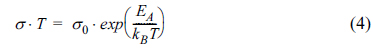
where, σ0 is a pre-exponential factor related to the effective number of electrons and mobile oxygen ions, EA is the activation energy for electrical conduction processes, and kB and T denote the Boltzmann constant and absolute temperature, respectively. The dashed lines in Fig. 4 (b) are linear least-squares fits of the electrical conductivities, while Table 1 summarizes the activation energies derived from the straight lines.
Fig. 4.
(a) Electrochemical conductivity of the SYT and SYTF0.5 in reducing (10% H2 balanced in N2), inert (N2), and oxidizing (Air) environment at varying temperature (600-900℃). (b) Arrhenius plots of the electrical conductivity corresponding to (a).
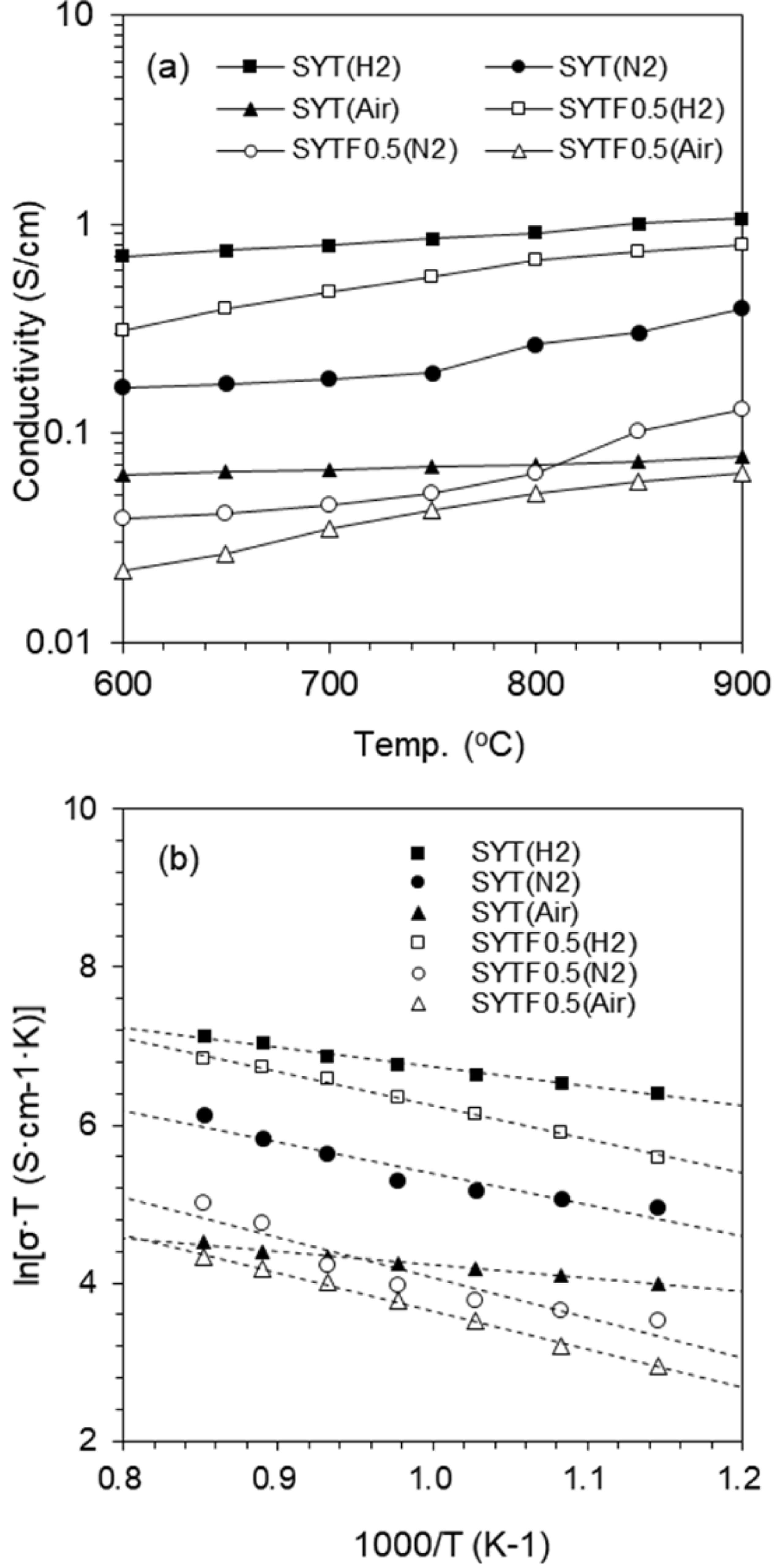
Table 1.
Summary of the activation energies for the total electrical conductivities analyzed with the straight lines of Fig. 4 (b).

Fig. 5 shows the XRD patterns of SYTF0.5/8YSZ mixture to investigate the chemical compatibility of the SYTF0.5 anode with the 8YSZ electrolyte. To verify the by-product formation between anode/electrolyte interlayer during the sintering process, the mixture of the 8YSZ electrolyte and SYTF0.5 anode was co-fired under the anode sintering condition (1,200℃/10 h/air). No apparent by-products patterns were detected in the XRD, other than the SYTF0.5 phase and the 8YSZ phase.
Fig. 5.
Chemical compatibility analysis based on X-ray diffraction patterns of SYTF0.5/8YSZ mixture sintered at 1,200℃ in H2 for 10 h.
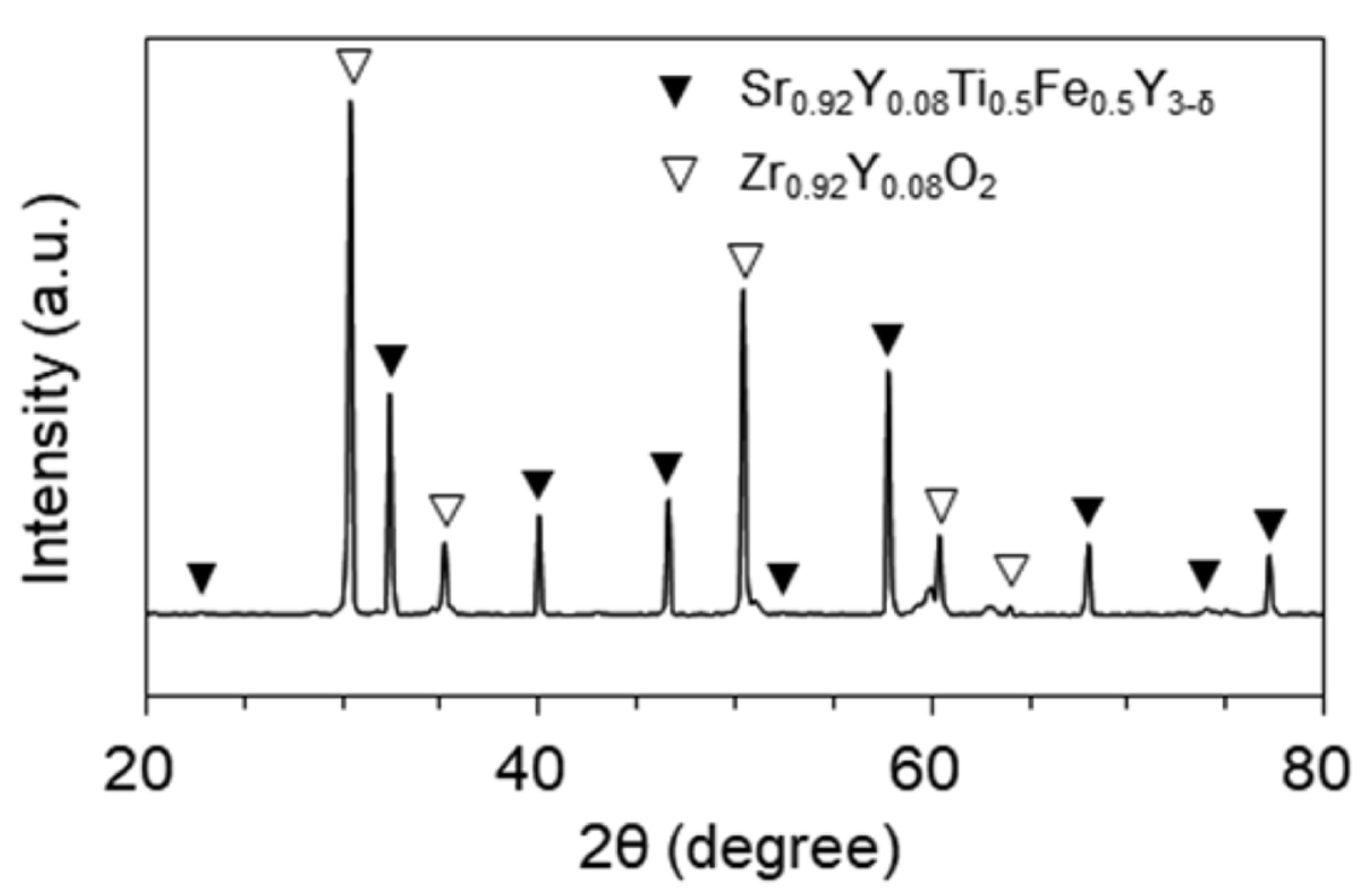
Fig. 6 (a) shows impedance spectra of the SYT anode and the SYTF0.5 anode. Electrolyte supported single cells were prepared with the LSM/8YSZ/SYT or SYTF0.5. The experimental was carried out at 800 and 900℃ in H2 under OCV condition. Even though the SYT anode has ionic conductivity by reducing TiO2-δ in H2, electronic conductivity would be the major contribution to electrical conductivity in the SYT anode by A-site substitution. Therefore, the SYT anode has limited MIEC property. Otherwise, a B-site substitution exhibited in the SYTF0.5 anode improves the ionic conductivity, as well as the electronic conductivity, via A-site substitution, leading to good MIEC property. The improved MIEC property exhibited in the SYTF0.5 anode could lead to lower polarization resistance, compared to the SYT anode. Fig. 6 (b) shows the IV-characteristics with the same experimental conditions as Fig. 6 (a). The data were recorded after stabilizing the system for approximately 30 min. The maximum power densities of the SYT anode were 56.9 mW/cm2 at 900℃. Otherwise, the maximum power densities of the SYTF0.5 anode at (800 and 900)℃ were (68.4 and 98.6) mW/cm2, respectively, due to the improved MIEC property of the SYTF0.5 anode.
Fig. 6.
(a) Impedance spectra of the SYT anode and the SYTF0.5 anode measured at 800 and 900℃ in H2 under OCV condition. (b) IV-characteristics of the SYT anode and the SYTF0.5 anode at 900℃ in H2.

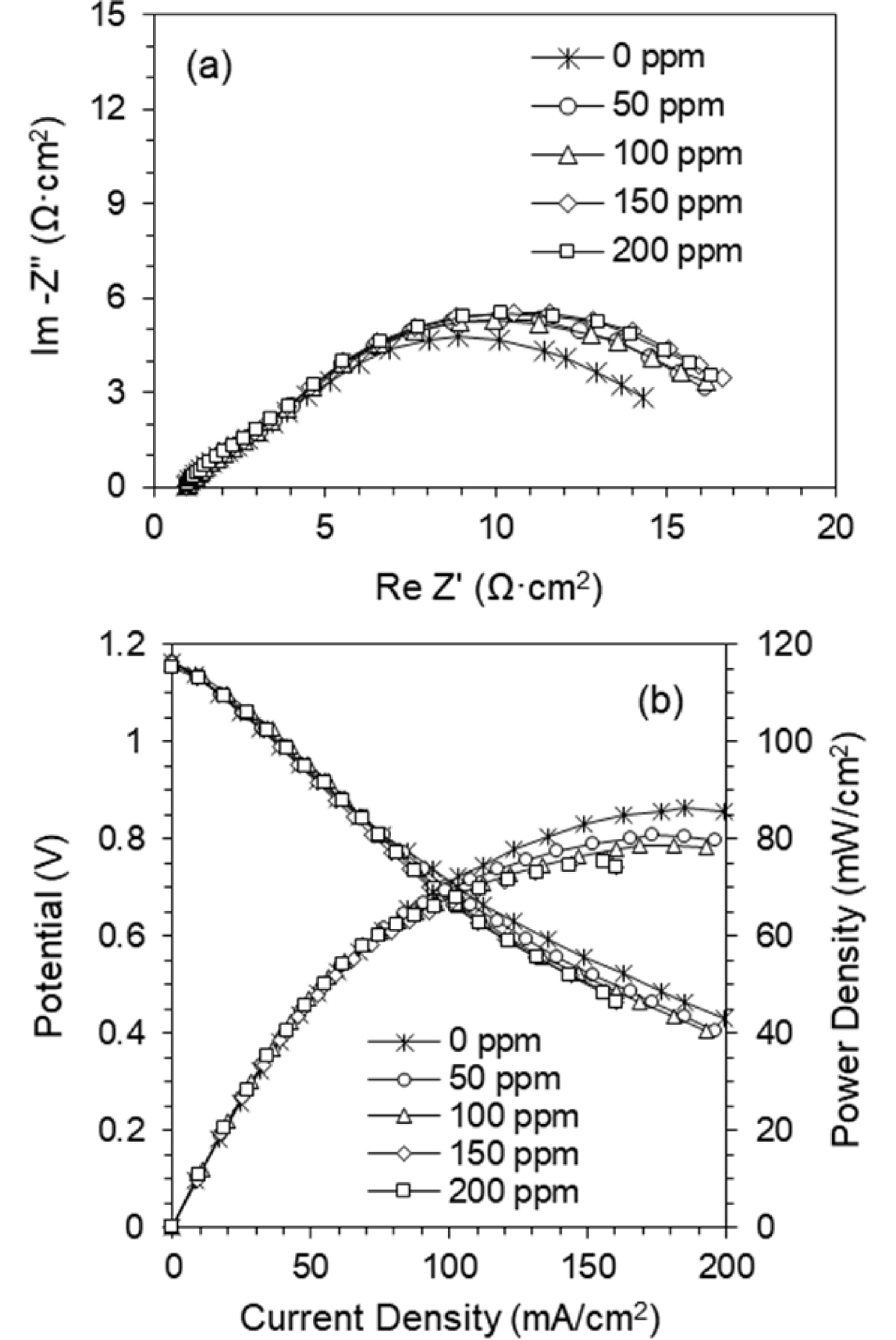
Fig. 7 shows H2S tolerant effects on the SYTF0.5 anode with the impedance spectra in Fig. 7 (a) and the IV-characteristics in Fig. 7 (b). To investigate the electrochemical property by H2S concentration in the fuel, the electrolyte supported button-type single cells with LSM/8YSZ/SYTF0.5 were prepared. The impedance spectra of the cell were obtained under OCV condition, and measured at 900℃ in a gas mixture of H2 and H2S. The spectra were measured after 2 h of H2S exposure, to stabilize, and to reach quasiequilibrium. Because of the constant conditions of the LSM cathode and the YSZ electrolyte, the response of the impedance spectra is caused by the anode polarization resistance from sulfur poisoning. The polarization resistance was stable up to 200 ppm of H2S exposure, compared to the conventional Ni/YSZ anode. In our previous research, the cell perfor-mance of the Ni/YSZ drastically and irreversibly decreased over 40%, even in 100 ppm of H2S exposure [27]. The extended electrochemical reaction sites beyond the TPB area could confine H2S poisoning, as well as the excellent resistance property exhibited in the MIEC oxides for sulfur poisoning. The cell performance loss in sulfur poisoning to the SOFC anodes can be attributed to physical adsorption and chemisorption of H2S at the active site of the anode surface. The loss of the electrochemical reaction site can directly affect the performance. The adsorbed sulfur can react with anode materials for long-term operation to form the sulfides, resulting in the loss of electrical conductivity, stability, and catalytic activity. The possible electrochemical oxidations of sulfur on the SOFC anode are given by:


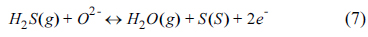
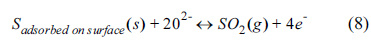
Sulfur can be produced from H2S decomposition via reaction (5), leading to physical or chemical surface adsorption. SO2 formed via reactions (6) and (8) may further react with excess H2S to produce sulfur. Because SO2 shows a more stable thermodynamic phase than H2S and S, the reverse reactions in (6) and (8) may be less probable in SOFC operation condition. Therefore, the reactions (6) and (8) are favorable for the sulfur tolerance of anode, and excess O2- at the TPB area or reaction sites increases the prominence of reactions (6) and (8). The MIEC property exhibited in the SYTF0.5 anode by Fe3+ substitution could provide O2- on the electrochemical reaction sites via reactions (6) and (8), to form SO2, electrochemically leading to improved H2S tolerance on the anode. The results shows that other aliovalent substitution in the Ti4+ of B-site instead of Fe3+ may play a same role in the ionic conductivity leading to improvement of H2S tolerance. We are investigating Ni2+ dopant effects of the sulfur tolerance and the results will be contributed in our further research. Fig. 7 (b) shows the I-V characteristics with varying H2S concentration (0-200 ppm) at 900℃ in the SYTF0.5 anode. The data of the cell performance were obtained after reaching a quasisteady state after the H2S introduction. The maximum power densities were slightly decreased by 13% (86.3 to 75.2 mW/cm2 at 0 to 200 ppm), compared to Ni/YSZ anode. The extended electrochemical reaction beyond the TPB via B-site substitution of Fe3+ might improve the H2S tolerance, as well as increase the cell performance.
4. Conclusions
Electrochemical characteristics of the SYTF0.5 were investigated in H2 fuels containing H2S, to assess the feasibility of the oxide materials as alternative anodes. The electrical conductivity of the SYTF0.5 was lower than that of the SYT, even though additional ionic conductivity was introduced by aliovalent substitution of the B-site of Ti4+ by Fe3+. The defect association between the electron pair in strontium vacancy and the oxygen vacancy with two electron-hole pairs exhibited in the SYTF0.5 might decrease the electrical conductivity. Because of the additional ionic conductivity introduced by Fe3+ substitution, the electrochemical performance of the SYTF0.5 anode was improved. The maximum power densities for the SYT anode and the SYTF0.5 anode in H2 at 900℃ were 56.9 and 98.6 mW/cm2, respectively. The maximum power density in the SYTF0.5 anode at 200 ppm of H2S concentration decreased by 13%. The MIEC property exhibited in the SYTF0.5 anode would expand electrochemical oxidation area to the whole anode surface, as well as TPB, resulting in decrease of the overall anode polarization resistance. The additional ionic conductivity of Ti4+ substitution by Fe3+ would likely provide O2- on the electrochemical reaction sites to electrochemically form SO2, leading to improved H2S tolerance on the anode.


