


Poly(Imide) Separator Functionalized by Melamine Phosphonic Acid for Regulating Structural and Thermal Stabilities of Lithium-ion Batteries
- Ye Jin Jeon1,2, Juhwi Park1,2, Taeeun Yim1,2,*
- Received January 15, 2024 Accepted March 5, 2024
- ABSTRACT
-
As the energy density of lithium-ion batteries (LIBs) continues to increase, various separators are being developed to with the aim of improving the safety performance. Although poly(imide) (PI)-based separators are widely used, it is difficult to control their pore size and distribution, and this may further increase the risk associated. Herein, a melamine phosphonic acid (MP)-coated PI separator that can effectively control the pore structure of the substrate is suggested as a remedy. After the MP material is embedded into the PI separator with a simple one-step casting process, it effectively clogs the large pores of the PI separator, preventing the occurrence of internal short circuits during charging. It is anticipated that the MP material can also suppress rapid thermal runaway upon cycling due to its ability to reduce the internal temperature of the LIB cell caused by the desirable endothermic behavior around 300°C. According to experiments, the MP-coated PI separator not only decreases the thermal shrinkage rate better than commercial poly(ethylene) (PE) separators but also exhibits a desirable Gurley number (109.6 s/100 cc) and electrolyte uptake rate (240%), which is unique. The proposed separator is electrochemically stable in the range 0.0–5.0 V (vs. Li/Li+), which is the typical working potential of conventional electrode materials. In practice, the MP-coated PI separator exhibits stable cycling performance in a graphite–LiNi0.83Co0.10Mn0.07O2 full cell without an internal short circuit (retention: 90.3%).
- 1. Introduction
- 1. Introduction
The use of thermally stable separators in lithium-ion batteries (LIBs) has increased in recent years, given the continuing attempts to increase their energy density [1–4]. Many advanced electrode materials must offer a high specific capacity and working potential [5–10]; this further increases the need to ensure the safety of high-density LIBs as they may cause severe accidents with abnormal use [11–15]. Therefore, to improve the safety of LIBs, the use of separators has garnered significant attention over the past few years.The separator is located between the electrodes to prevent electron migration, and several insulating materials have been developed [16–18]. The most frequent types are made from poly(olefin)-based poly(ethylene) (PE) and poly(propylene) (PP), as they provide effective insulation (~1014 Ω cm) and can be mass-produced [19–24]. Moreover, as these polymeric materials are cost-effective compared to other insulating materials, poly(olefin)-based materials have served as a core separator since the first commercialization of LIBs [25–27].Although poly(olefin)-based materials, especially in PE, have been used in LIBs, their relatively unstable thermal behaviors still remain a limitation. Note that the cells could be ignited by abnormal use, then the temperature of the cells is rapidly increased by combustion reaction with flammable electrolytes at early state [28–32] because PE separators are only thermally stable up to approximately 130°C [33–36]. When the PE separator is melted in the cell, electrons in each electrode can move from electrode to electrode because each electrode is no longer physically separated. This further leads to severe thermal runaway of LIBs via a sudden exothermic reaction. It should be noted that with the increasing energy density of LIBs, safety risks also increase significantly; therefore, cost-effective separators with more reliable thermal stability are urgently needed.Herein, we propose poly(imide) (PI)-based separator, which can greatly improve the safety of LIBs in Fig. 1(a). The PI separator is thermally stable above 250°C [37–40]; hence, it is anticipated that electric circuit can be prevented even at a high temperature, thereby allowing the safety of LIBs. However, the current PI separator is composed of large pores: even if PI separators are thermally stable, large pores are involved with the electric short circuit at the cell assembling stage, therefore, it is difficult to maintain stable cycling behavior. This means that relatively large pores of the PI separator should be clogged in order to allow stable cycling of LIBs. In this respect, the PI separator is modified by embedding the melamine phosphonic acid (MP) to reduce the pore size of the PI separator. Notably, the MP not only clogs the large pore of the PI separator but also contributes to increasing the safety of LIBs: when the MP is exposed to high temperature (around 300°C), it is decomposed by endothermic reaction (can act as a heat absorbent), thereby decreasing the temperature of the cell. Based on these considerations, a size-controlled MP-coated PI separator is prepared and its physical and electrochemical behaviors are elucidated.
- 2. Experimental
- 2. Experimental
To prepare the MP material, 12.6 g of melamine (Sigma-Aldrich, 0.1 mol) and 7.9 g of phenylphosphonic acid (Sigma-Aldrich) were dissolved in 50 mL water. The mixture was then stirred at 80°C for 12 h, and the solid products were filtrated and decanted with the water and ethanol to remove residual impurities. The solids products were dried at 80°C for 12 h. The MP products were then milled at 450 rpm for 5 h to control the particle size. For coating the MP materials onto the PI separator, a coating solution was prepared using 0.05 g MP, 0.2 g poly(vinylidene fluoride-co-hexafluoropropylene) (PVDF-HFP, Sigma-Aldrich), and 2.5 mL of N-methyl pyrrolidone (NMP, Sigma-Aldrich). The mixture was stirred for 1 h, and the slurry was cast onto the PI separator. The MP-coated PI separator was dried at 60°C for 12 h and subsequently further dried at 60°C for 12 h in a vacuum oven. The loading density of MP materials onto the PI separators is 0.85 mg cm−2.The surface morphologies were then characterized via scanning electron microscopy (SEM; JSM-7800F, JEOL), and the thermal behaviors of MP products were characterized by differential scanning calorimetry (DSC; Sinco M&T) at a heating rate of 10°C min−1 from room temperature to 400°C in N2 atmosphere. To measure the shrinkage behavior, each separator (19 pi) was placed in an oven wherein the temperature was controlled for 30 min each at 80, 135, 150, 180, and 200°C. To estimate the effect of MP materials on the porous structure of the PI separator, the Gurley number (GN) of each separator was measured using a Gurley densometer (Gurley Precision Instruments). The GN values indicate the time it takes 100 seconds of air to pass from one side to the other between separators: the smaller the GN value, the more pore structures are developed. The mechanical properties of each separator were measured using a tensile tester (JSV H1000, Coretech) using a 2.0 × 5.0 cm area of each separator. To quantify the rate of electrolyte uptake, 19 pi separators were immersed in an electrolyte (EC:EMC=1:2 (v/v%) + 1 M LiPF6, Donghwa Electrolyte) for 1 h and dried for 1 h. The rate of electrolyte uptake was calculated by subtracting the weight of the dried separator from that of the wetted separator and dividing it by the weight of the dried separator.Linear sweep voltammetry (LSV, Biologic) was performed using a cell assembled with stainless steel (working electrode), Li metal (counter and reference electrodes), and each separator. The cells were then scanned from 2.5 to 0.0 V (vs. Li/Li+) and from 3.0 to 5.0 V (vs. Li/Li+) at a rate of 0.1 mV s−1. To evaluate the electrochemical performance, a cathode slurry was prepared with 1.8 g LiNi0.83Co0.10Mn0.07O2 (NCM; L&F materials), 0.1 g of poly(vinylidene fluoride) (Kureha), and 0.1 g of a carbon-conducting agent (Super-C, C-NERGY), dispersed in 1.8 mL N-methyl pyrrolidone (Sigma-Aldrich). It was stirred for 1 h and cast onto an Al current collector. The NCM cathode was dried at 120°C in a vacuum oven for 12 h. For the anode, 1.95 g graphite (BTR), 0.04 g styrene butadiene rubber (ZEON), and 0.02 g carboxymethyl cellulose (Daicel Fine Chem Ltd.) were dispersed in 2.0 mL of water, and it was further agitated for 30 min. The slurries were then coated on a Cu current collector and further dried at 110°C for 11 h in a vacuum oven. The full-cells were assembled with NCM cathode, graphite anode, electrolyte, and each separator. The full-cells were cycled from 2.8 and 4.2 V with a current rate of 0.1 C for two cycles (formation step), and the current rate was subsequently increased to 1.0 C.
- 3. Results and Discussion
- 3. Results and Discussion
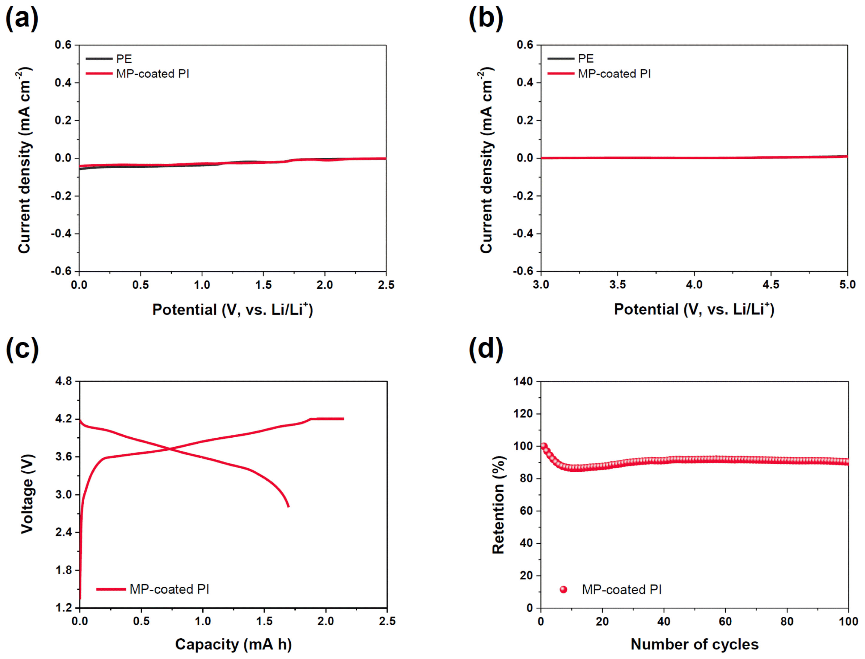
After the coating process, the surface morphologies of the PE-, PI-, and MP-coated PI separators were examined using SEM in Fig. 1(b). In the PE separator, the inner pore evenly existed at sizes less than 1 μm, which should effectively prevent internal short circuits between electrodes. In contrast, the pore sizes in the PI separator were larger, and their distribution was not uniformly controlled, which is inherently inappropriate for LIBs. In the MP-coated PI separator, extremely large pores were clogged well, and the surface morphologies became more regular afterward. This indicates that an MP-coated PI separator can be used as an alternative separator for LIBs.To elucidate the role of the MP coating, the DSC profile was examined in Fig. 2(a). When the temperature was increased from room temperature to 400°C, three sharp peaks were observed in the DSC profile at 293.2, 327.1, and 371.4°C, indicating endothermic reactions. Notably, phenylphosphonic acid composed of MP material thermally decomposes at 293.2°C [41]. As a result, it forms an H3PO4 product via H2O and LiPO3 intermediates [42]. Furthermore, near 327.1°C, the thermal decomposition of H3PO4 and ammonia from the MP material occurs with a noticeable endothermic reaction [43]. Then, the CN functional group thermally decomposes in the second thermal decomposition step, resulting in the formation of HCN gas [44]. This process requires a large amount of endothermic heat, which is expected to effectively suppress any thermal runaway behavior of the LIB cell.In our test, embedding the MP material into the separator improved its shrinkage behavior in Fig. 2(b). To evaluate this behavior more thoroughly, each separator was placed in an oven at the relevant temperature for 30 min, and the changes in dimensions were monitored accordingly. Until 135°C, there were negligible changes to the separator dimensions, regardless of the substrate or MP coating. However, the PE separator shrunk severely after 150°C from 80.1% at 150°C to 0.8% at 200°C. Alternatively, the MP-coated PI separators exhibited stable shrinkage behaviors, even after 200°C, due to the thermally stable PI substrate offering enhanced thermal stability. Therefore, an additional evaluation of the shrinkage behavior of the MP-coated PE separator was performed to evaluate these differences. Interestingly, the MP-coated PE separator shrunk after 150°C at a rate similar to (but not larger than) the PE separator. Specifically, the shrinkage rate of the MP-coated PE separator was 29.0% at 150°C and reached 36.0% at 200°C, which is a much less dangerous shrinkage rate. This indicates that the MP coating is effective in improving the thermal properties of separators.The physical and mechanical properties of each separator were characterized as shown in Fig. 3(a). According to the GN, the commercialized PE separator exhibited a value of 235.7 s/100 cc, meaning that it takes 235.7 s for air to permeate and traverse the separator. The PI separator showed a GN of 4.4 s/100 cc, indicating a far more rapid permeation due to the larger pores, which could potentially cause internal short circuits [45–47]. In contrast, the GN of the MP-coated PI separator was well controlled, showing a GN of 109.6 s/100 cc, which indicated that the inner pores of the PI separator were well-clogged. From tensile strength tests in Fig. 3(b), the PE separator exhibited an ultimate strength of 79.7 MPa as the polyolefin substrate was tied well together. In contrast, the PI separator revealed a severely decreased ultimate strength (0.59 MPa) as it was prepared by an electrospinning process, which does not offer high mechanical properties [48–50]. Nevertheless, the ultimate strength markedly increased in the MP-coated PI separator (26.5 MPa), indicating improved mechanical properties.The wettability of each separator was also examined in Fig. 3(c). Each separator was placed on a desk, the electrolyte (0.1 mL) was dropped, and changes in the surface of each separator were monitored for 1 min. After the dropwise addition of the electrolyte, most of the PE separator was wetted; however, the outer side of the separator was not properly wetted after 1 min. Recalling that the PE separator is composed of dense inner pores, more time was needed for wetting. On the other hand, the electrolyte immediately soaked into the PI-based separator due to its large pores. After a sufficient wettability period in Fig. 3(d), the PE separator showed an electrolyte uptake rate of 179%, indicating moderate compatibility between the electrolyte and separator [51,52]. Interestingly, the PI separator exhibited a low electrolyte uptake of 58%, and this may be attributed to the large pores, providing an unfavorable absorption environment. Hence, most of the electrolytes could not be stored within the PI separator. In contrast, the MP-coated PI separator exhibited an electrolyte uptake rate of 240%, indicating that Li+ migration was greatly facilitated. Because a PVDF binder was used to embed the MP material onto the PI separator, electrolyte uptake was likely accelerated [53,54].The electrochemical behaviors of each separator were analyzed using LSV, as shown in Fig. 4. In both cathodic and anodic polarizations in Fig. 4(a,b), no distinctive current associated with irreversible decomposition was observed in the PE separator. The PI separator was difficult to evaluate with LSV as an internal short circuit occurred (its open circuit potential was immediately dropped to 0.0 V (vs. Li/Li+) once the cell was fabricated). However, the MP-coated PI separator exhibited stable open-circuit potential with stable electrochemical behaviors in both the cathodic and anodic polarizations. In summary, the MP material did not cause any trade-off effects in terms of irreversible electrochemical decomposition upon cycling. This behavior was also observed in the graphite/NCM full cells, as shown in Fig. 4(c,d). During the initial cycle, cells MP-coated PI separators displayed normal voltage profiles. In contrast, a severe internal short circuit was observed in the cell with the PI separator, which was predictable. This suggests that the individual use of a PI separator does not ensure prolonged and stable cycling performance. As such, the MP-coated PI separator exhibited stable cycling behaviors and offered a retention rate of 90.3% after 100 cycles [55,56]. From these results, it can be concluded that the MP-coated PI separator is highly compatible with LIBs due to its improved thermal, mechanical, and electrochemical performance.
- 4. Conclusions
- 4. Conclusions
In this study, we characterized an MP-coated PI separator that effectively controls the thermal stability of LiBs based on its desirable endothermic reactions. The MP material clogs the larger pores of the PI separator, effectively preventing internal short circuits during charging. Hence, it is anticipated that the MP addition will strongly reduce the opportunity for runaway thermal reactions owing to its desirable endothermic behaviors at ~300°C. The MP-coated PI separator exhibited a lower thermal shrinkage rate compared to the commercial PE separator, indicating a proper GN value, in addition to superior wettability with conventional electrolytes and their uptake rate. The MP-coated PI separator was stable in the range 0.0–5.0 V (vs. Li/Li+), which is the typical potential range for LIBs. In practice, the MP-coated PI separator exhibited stable cycling performance with a graphite/NCM full cell without an internal short circuit, which further demonstrates the efficacy of the MP solution.
- Acknowledgments
- Acknowledgments
This work was supported by Incheon National University Research Grant in 2022.
Fig. 1
(a) Scheme for the preparation of MP-coated PI separator. SEM images of (b) PE, (c) PI, and (d) MP-coated PI separators.

Fig. 2
(a) DSC curve of the MP; (b) thermal shrinkage behaviors of PE, MP-coated PE, PI, and MP-coated PI separators.

Fig. 3
Physicochemical properties of each separator: (a) Gurley number, (b) tensile strength, (c) electrolyte wettability, and (d) electrolyte uptake (black: PE, grey: PI, and red: MP-coated PI separators).

Fig. 4
Linear sweep voltammetry of cells with PE and MP-coated PI separators for (a) cathodic polarization and (b) anodic polarization. (c) Voltage profiles of the graphite/NCM full cells with PE, PI, and MP-coated PI separators. (d) Cycling performances of the cells with MP-coated PI separator at 45°C.
- REFERENCES
- REFERENCES
References
[1] M. Waqas, S. Ali, C. Feng, D. Chen, J. Han and W. He, Small., 2019, 15(33), 1901689.[5] J.-L. Shi, D.-D. Xiao, M. Ge, X. Yu, Y. Chu, X. Huang, X.-D. Zhang, Y.-X. Yin, X.-Q. Yang, Y.-G. Guo, L. Gu and L.-J. Wan, Adv. Mater., 2018, 30(9), 1705575.[6] M. Du, K. Huang, Y. Guo, Z. Xie, H. Jiang, C. Li and Y. Chen, J. Power Sources., 2019, 424, 91–99.
[Article][7] T. Zhang, Y. Ma, B. Huang and Y. Dai, ACS Appl. Mater. Interfaces., 2019, 11(6), 6104–6110.
[Article][8] D. Luo, G. Li, C. Fu, J. Zheng, J. Fan, Q. Li and L. Li, Adv. Energy Mater., 2014, 4(11), 1400062.[9] Y. Orooji, Z. Nezafat, M. Nasrollahzadeh, N. Shafiei, M. Afsari, K. Pakzad and A. Razmjou, Desalination., 2022, 529, 115624.
[Article][10] A. S. A. Rahim, M. Z. Kufian, A. K. M. Arof and Z. Osman, J. Electrochem. Sci. Technol., 2022, 13(1), 128–137.
[Article][11] T. H. Kim, S. H. Kim, S. S. Park, M. S. Kang, S. S. Kim, H.-S. Kim and G. Jeong, J. Electrochem. Sci. Technol., 2023, 14(4), 369–376.
[Article][13] Z. Liu, Y. Jiang, Q. Hu, S. Guo, L. Yu, Q. Li, Q. Liu and X. Hu, Energy Environ. Mater., 2020, 4(3), 336–362.
[Article][15] T. M. Nguyen, J. Suk and Y. Kang, J. Electrochem. Sci. Technol., 2019, 10(2), 250–255.[16] L. Peng, X. Wang, J. Dai, X. Shen, B. Huang, P. Zhang and J. Zhao, Mater. Chem. Front., 2021, 5(4), 1884–1894.
[Article][17] Z. Wang, R. Pan, C. Ruan, K. Edstrom, M. Stromme and L. Nyholm, Adv. Sci., 2018, 5(3), 1700663.[19] J. C. Barbosa, J. P. Dias, S. Lanceros-Mendez and C. M. Costa, Membranes., 2018, 8(3), 45.
[Article][22] K. J. Kim, J.-H. Kim, M.-S. Park, H. K. Kwon, H. Kim and Y.-J. Kim, J. Power Sources., 2012, 198, 298–302.
[Article][24] Y.-J. Kim, S.-M. Lee, S. H. Kim and H.-S. Kim, J. Electrochem. Sci. Technol., 2015, 6(1), 26–33.
[Article][25] B. Yuan, K. Wen, D. Chen, Y. Liu, Y. Dong, C. Feng, Y. Han, J. Han, Y. Zhang, C. Xia, A. Sun and W. He, Adv. Funct. Mater., 2021, 31(32), 2101420.[26] J. Li, Y. Zhang, R. Shang, C. Cheng, Y. Cheng, J. Xing, Z. Wei and Y. Zhao, Energy Stor. Mater., 2021, 43, 143–157.
[Article][27] W. Zhang, Z. Tu, J. Qian, S. Choudhury, L. A. Archer and Y. Lu, Small., 2018, 14(11), 1703001.[28] C. Martinez-Cisneros, C. Antonelli, B. Levenfeld, A. Varez and J.-Y. Sanchez, Electrochim. Acta., 2016, 216, 68–78.
[Article][29] R. l’Abee, F. DaRosa, M. J. Armstrong, M. M. Hantel and D. Mourzagh, J. Power Sources., 2017, 345, 202–211.[30] S. Sun, J. Wang, X. Chen, Q. Ma, Y. Wang, K. Yang, X. Yao, Z. Yang, J. Liu, H. Xu, Q. Cai, Y. Zhao and W. Yan, Adv. Energy Mater., 2022, 12(41), 2202206.[31] C. J. Orendorff, T. N. Lambert, C. A. Chavez, M. Bencomo and K. R. Fenton, Adv. Energy Mater., 2012, 3(3), 314–320.
[Article][32] H. Zhou, C. Fear, M. Parekh, F. Gray, J. Fleetwood, T. Adams, V. Tomar, V. G. Pol and P. P. Mukherjee, J. Electrochem. Soc., 2022, 169(9), 090521.
[Article][38] I.-H. Tseng, J.-C. Chang, S.-L. Huang and M.-H. Tsai, Polym. Int., 2012, 62(5), 827–835.
[Article][39] M. Cai, H. He, X. Zhang, X. Yan, J. Li, F. Chen, D. Yuan and X. Ning, Nanomaterials., 2018, 9(1), 39.
[Article][40] P. Ma, C. Dai, H. Wang, Z. Li, H. Liu, W. Li and C. Yang, Compos. Commun., 2019, 16, 84–93.
[Article][41] M.-J. Chen, Z.-B. Shao, X.-L. Wang, L. Chen and Y.-Z. Wang, Ind. Eng. Chem. Res., 2012, 51(29), 9769–9776.
[Article][42] I. Kundrata, A. Mošková, M. Moško, M. Mičušík, E. Dobročka and K. Fröhlich, J. Vac. Sci. Technol. A., 2021, 39(6), 062407.[43] B. Boonchom and C. Danvirutai, J. Optoelectron. Biomed. Mater., 2009, 1(1), 155–123.[44] J. Liu, X. Zhang, B. Hu, Q. Lu, D. Liu, C. Dong and Y. Yang, J. Energy Inst., 2020, 93(2), 649–657.
[Article][45] H. Zhang, C.-E. Lin, M.-Y. Zhou, A. E. John and B.-K. Zhu, Electrochim. Acta., 2016, 187, 125–133.
[Article][46] M. Li, Z. Zhang, Y. Yin, W. Guo, Y. Bai, F. Zhang, B. Zhao, F. Shen and X. Han, ACS Appl. Mater. Interfaces., 2020, 12(3), 3610–3616.
[Article][47] Y. Wang, M. Guo, H. Fu, Z. Wu, Y. Zhang, G. Chao, S. Chen, L. Zhang and T. Liu, J. Membr. Sci., 2022, 662, 121004.
[Article][48] M. Li, L. Sheng, R. Xu, Y. Yang, Y. Bai, S. Song, G. Liu, T. Wang, X. Huang and J. He, Compos. Commun., 2021, 24, 100607.
[Article][49] Y. Deng, Y. Pan, Z. Zhang, Y. Fu, L. Gong, C. Liu, J. Yang, H. Zhang and X. Cheng, Adv. Funct. Mater., 2022, 32(4), 2106176.[51] Y. Xie, H. Zou, H. Xiang, R. Xia, D. Liang, P. Shi, S. Dai and H. Wang, J. Membr. Sci., 2016, 503, 25–30.
[Article][52] J.-L. Shi, L.-F. Fang, H. Li, H. Zhang, B.-K. Zhu and L.-P. Zhu, J. Membr. Sci., 2013, 437, 160–168.
[Article][53] H. Chen, M. Ling, L. Hencz, H. Y. Ling, G. Li, Z. Lin, G. Liu and S. Zhang, Chem. Rev., 2018, 118(18), 8936–8982.
[Article][54] H. Y. Tran, M. Wohlfahrt-Mehrens and S. Dsoke, J. Power Sources., 2017, 342, 301–312.
[Article][55] Y. Wang, C. Yin, Z. Song, Q. Wang, Y. Lan, J. Luo, L. Bo, Z. Yue, F. Sun and X. Li, Materials., 2019, 12(19), 3125.
[Article][56] H. An, Y. Roh, Y. Jo, H. Lee, M. Lim, M. Lee, Y. M. Lee and H. Lee, Energy Environ. Mater., 2023, 6(5), e12397.