Silicon-Based Anode with High Capacity and Performance Produced by Magnesiothermic Coreduction of Silicon Dioxide and Hexachlorobenzene
Article information
Abstract
Silicon (Si) has been considered as a promising anode material because of its abundant reserves in nature, low lithium ion (Li+) intercalation/de-intercalation potential (below 0.5 V vs. Li/Li+) and high theoretical capacity of 4200 mA h/g. In this paper, we prepared a silicon-based (Si-based) anode material containing a small amount of silicon carbide by using magnesiothermic coreduction of silica and hexachlorobenzene. Because of good conductivity of silicon carbide, the cycle performance of the silicon-based anode materials containing few silicon carbide is greatly improved compared with pure silicon. The raw materials were formulated according to a silicon-carbon molar ratio of 10:0, 10:1, 10:2 and 10:3, and the obtained products were purified and tested for their electrochemical properties. After 1000 cycles, the specific capacities of the materials with silicon-carbon molar ratios of 10:0, 10:1, 10:2 and 10:3 were still up to 412.3 mA h/g, 970.3 mA h/g, 875.0 mA h/g and 788.6 mA h/g, respectively. Although most of the added carbon reacted with silicon to form silicon carbide, because of the good conductivity of silicon carbide, the cycle performance of silicon-based anode materials was significantly better than that of pure silicon.
1. Introduction
Silicon (Si) is a promising anode material due to its high theoretical capacity of 4200 mA h/g, low lithium ion (Li+) intercalation/de-intercalation potential (below 0.5 V vs. Li/Li+) and abundant reserves in nature [1–5]. However, the electronic conductivity of the Si is poor, which can’t support the charge/discharge of heavy current density [6]. In the Li insertion/extraction process Si has huge volume expansion/shrinkage (over 300%), which leads to the dramatic crack of the Si particle and pulverization from the current collector [7]. To suppress the volume expansion and enhance the conductivity of the Si electrode to improve its cycle life and rate capability is a meaningful thing [8]. In this respect many research work has been done, such as nanostructuring strategies including nanoparticles [9], nanowires [10], nanotubes [11], nanosheets [12]. It has been proved that porous nanostructures [13,14] can effectively improve the cyclic performance of the Si anode. Carbon-silicon compositing also has been considered as a simple and highly efficient way to boost the electrochemical performance of the Si anode. The carbon in the carbon-silicon composites can effectively buffer the severe volume change of Si anode in Li insertion/extraction process. Carbon is a good conductive material and can improve the electrical conductivity of the Si anode [15–17]. It is worth mentioning that stoichiometric SiOx based materials can also effectively alleviate the volume Si volume changes during alloying/dealloying with Li+ [18]. In this regard, Min-Sik Park and his group have done a lot of work [19–22]. Eunjun Park et al. prepared a dual-size Si nanocrystal-embedded SiOx nanocomposite via cost-effective sol-gel reaction of triethoxysilane with commercially available Si nanoparticles as a high-capacity Li+ storage material and the nanocomposite provided a high capacity (1914 mA h/g) with a notably improved initial efficiency (73.6%) and stable cycle performance over 100 cycles [19]; he also used a conductive polymer, poly(3,4-ethylenedioxythiophene): poly(4-styrenesulfonate) (PEDOT:PSS) as a flexible electrical interconnector to improve the electrochemical performance of Si/SiOx nanosphere anode materials for lithium ion batteries (LIBs) and the resulting Si/SiOx-PEDOT:PSS core-shell structured material with the small amount (1 wt%) of PEDOT:PSS showed the improved initial reversible capacity of 968.2 mA h/g with excellent long-term cycle performance over 200 cycles [20]. Jaewoo Lee et al. synthesized a gyroid three-dimensional network in a Si@SiOx/C nanoarchitecture which exhibits excellent electrochemical performance and enhanced thermal stability [21]; he also studied the effects of the oxygen concentration on the electrochemical properties of the nonstoichiometric silicon suboxide anode materials prepared by the method of magnesiothermic reduction of silica, and the results showed that the optimum Si/SiOx anode had not only high specific capacity with acceptable initial Coulombic efficiency, but also excellent cycling performance [22].
In this work, we adopted the method of magnesiothermic coreduction of silicon oxide and hexachlorobenzene, and the activated carbon atoms generated are firmly bonded to the silicon to improve the conductivity of the silicon and improve the cycle performance of the silicon. A large part of the carbon atoms reacts with silicon to form silicon carbide. Porous silicon carbide can be used as an anode in lithium batteries because of 300–460 Gpa Young’s modulus, high electric conductivity (0.1 Ω·m), and inactivity versus electrolyte compounds. Moreover, lithiation of Li+ ion into SiC lattice provides a theoretical capacity of 1430 mA h/g for Li2SiC that is suitable for the improvement of the capacity of a lithium battery [23]. In our experiments, because the silicon carbide is formed by chemically generated active silicon atoms and activated carbon atoms, the conductive network composed of silicon carbide can reach the inside of silicon deeply, and has a great effect on improving the conductivity of silicon, so a small amount of silicon carbide is advantageous for improving the electrochemical performance of silicon. The experimental results show that the anode materials composed of silicon and little carbon, silicon carbide obtained by the co-reduction method have better cycle stability and lower attenuation than pure silicon. However, as the amount of added carbon increases, excessive silicon carbide begins to degrade the performance of the anode materials.
2. Experimental
2.1 Materials and equipment
Silicon oxide powder, metal magnesium powder and hexachlorobenzene were purchased from Sinopharm Chemical Reagent Co. Ltd. and were used without further treatment. The high pressure reactor used for magnesiothermic coreduction of silicon dioxide and hexachlorobenzene is a self-made device as shown in Fig. 1. This device is made of 310S stainless steel, has a good sealing effect, and can withstand extreme pressure. It is suitable for use as a reactor for silicon dioxide, hexachlorobenzene and magnesium metal powder at high temperature. The inner diameter of the reactor is 16 mm, and the working volume of the device is 25 mL.
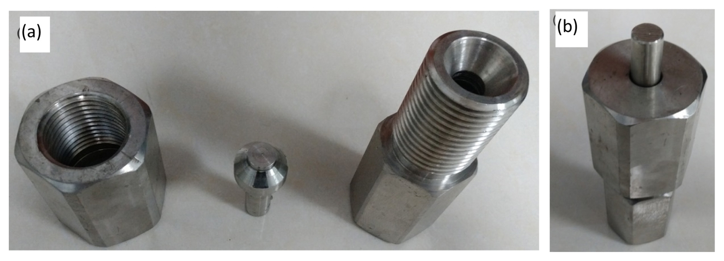
The photographs of a carbon-silicon composite anode material synthesis device: (a) high pressure reactor disassembly diagram, (b) assembled high pressure reactor.
2.2 Preparation of Si-based anode materials
Silicon oxide powder, metal magnesium powder and hexachlorobenzene were weighed according to a silicon-carbon molar ratio of 10:0, 10:1, 10:2 and 10:3, mixed together, and placed into the self-made high pressure reactor and reacted at 700°C for 6 hours. After the reaction was completed, the as-prepared products were washed with 20% hydrochloric acid and a large amount of distilled water, and then were dried in a 120°C incubator for 12 hours to obtain the Si-based anode products. The weight of each raw material used for reaction is shown in Table 1.

The weight of each raw material
The main chemical reactions are as follows:
2.3 Characterization
X-ray powder diffraction (XRD) patterns of the products were recorded on a Philips X’pert X-ray diffractometer with Cu Ka radiation (k = 1.54182 A°). The microstructures were observed on a scanning electron microscope (KYKY-2800B SEM).
Electrochemical performance was tested using coin-type (CR 2016) cells with lithium foil as counter and reference electrodes. The working electrode was fabricated by coating a paste of Si-based anode materials and polyvinylidene fluoride (PVDF) binder (90:10 wt.%) on an copper foil collector. The electrode was dried at 110°C for 12 h in a vacuum oven under vacuum before assembly into a coin cell in an argon-filled glove box. The nonaqueous electrolyte was 1M LiPF6 dissolved in an ethylene carbonate (EC)-dimethyl carbonate (DMC)-diethyl carbonate (DEC) mixture (1:1:1, in wt.%). Galvanostatic cycling experiments of the cells were performed on a LAND CT2001A battery test system in the voltage range of 0.001–1.5 V versus Li+/Li at room temperature.
3. Results and Discussion
3.1 XRD patterns of the Si-based anode materials
The XRD patterns of the four products obtained and the JCPD standard cards are shown in Fig. 2.
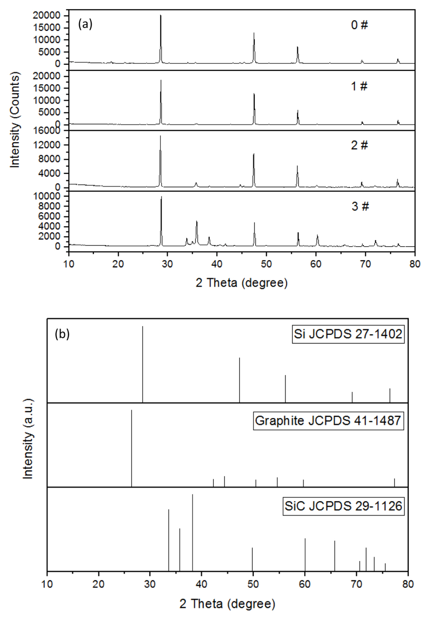
Comparison of XRD patterns of four samples with standard JCPDS cards ((a) is the XRD patterns for the four samples and (b) is the standard JCPDS cards).
It can be seen from the XRD patterns that the crystallinity of silicon in the product is better. As the amount of hexachlorobenzene in the raw materials increases, the corresponding peak of the crystal of silicon carbide in the product increases continuously, indicating that the amount of silicon carbide synthesized is increased. The peaks of graphite are not visible in the XRD patterns, indicating that the carbon obtained by the reduction of hexachlorobenzene by magnesium metal is not graphite-type carbon, and they may all react with silicon to form silicon carbide or a part of it may be present in the product in the form of amorphous carbon.
3.2 SEM-EDS analysis of the four samples
The SEM images of the four prepared samples are shown in Fig. 3.
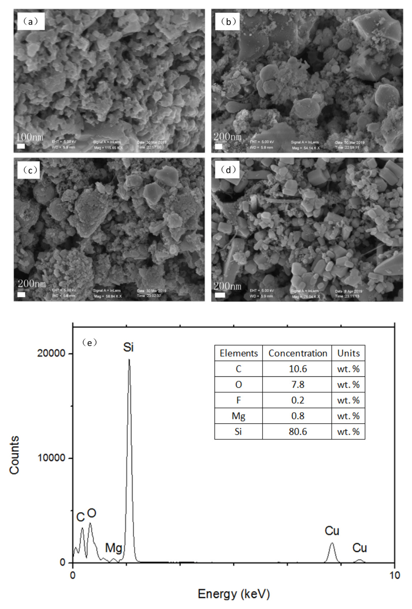
SEM images of the four prepared samples ((a), (b), (c), and (d) correspond to 0#, 1#, 2#, and 3# samples, respectively); (e) EDS spectra of 3# sample.
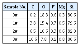
The element concentration (wt. %) of 0#, 1#, 2#, and 3# samples obtained through EDS analyses
It can be seen from the SEM images that the obtained product particles have a small particle size within a few tens to hundreds of nanometers, but the agglomeration is very common. The agglomeration may be due to a severe local exothermic reaction. The EDS results showed that the carbon content in the products was higher, but the oxygen content is lower compared with the results of Jaewoo Lee et al. [22]. This may be due to the reaction time was prolonged firstly, and secondly the reaction between hexachlorobenzene, silica and magnesium powder releases plenty of heat, which causes the temperature of the reaction system to rise sharply, then the chemical reaction is more complete.
3.3 Electrochemical performance
The obtained three Si-based anode materials were tested for electrochemical performance. The current density of 0.3 A g−1 was used for constant current charge and discharge tests, and the voltage range of the tests was 0.005–1.5V.
Through electrochemical performance tests, a small amount of silicon carbide formed by co-reduction promotes the battery performance. This may be because the generated silicon carbide improves the conductivity of the silicon. 0# is a pure silicon sample without carbon or silicon carbide, and after 1000 cycles, the specific capacity is reduced to 412.3 mA h/g, while under the same conditions, 1#, 2# and 3# are reduced to 970.3 mA h/g, 875.0 mA h/g and 788.6 mA h/g, respectively. The cycle performance is improved, but as the amount of the added carbon increases, the performance decreases, which may be due to excessive silicon carbide consuming the active silicon, also hindering the migration of lithium ions in the anode materials.
4. Conclusions
A silicon-based anode material doped with carbon and silicon carbide is prepared by co-reducing silicon oxide and hexachlorobenzene with metal magnesium powder. Compared with pure silicon anode material, the cycle performance of the silicon-based anode materials doped with carbon and silicon carbide is greatly improved because of the formed conductive network consisting of carbon and silicon carbide. However, with the further increase of the amount of carbon the performance of the Si-based anode materials will gradually decrease due to the formation of excessive bulk silicon carbide.

Electrochemical performance of four samples prepared by co-reduction. method: (a), (b), (c) and (d) are the specific capacity-voltage curves for the first, 500th and 1000th cycles of the 0#, 1#, 2# and 3# samples, respectively; (e) shows the decay curves of the specific capacities of the four samples with the number of cycles
Acknowledgement
This work is supported by the Doctor Foundation of Heze University (Grant No. XY20BS01).