A Self-standing and Binder-free Electrodes Fabricated from Carbon Nanotubes and an Electrodeposited Current Collector Applied in Lithium-ion Batteries
Article information
Abstract
In this paper, we report the preparation of a flexible, self-standing and binder-free carbon nanotubes (CNTs) electrode with an electro-generated current collector. The copper current collector layer was electrodeposited on the backside of CNTs self-standing film obtained by a simple filtration process. The obtained CNTs-Cu assembly was used as a negative electrode in Li-ion batteries exhibiting good performance along with proving its applicability in flexible batteries.
1. Introduction
The ubiquitous implementation of lithium-ion technology for energy storage had shaped our modern world and will definitely affect its future. Since the first development of lithium-ion batteries in Japan by Asahi Kasei [1] in 1991, and since its commercialization by Sony [2] in the same year, this technology attained great success due to its high energy density, power density and stable performance along with elucidating the formation of lithium dendrite. Research concerning energy storage systems that are capable of delivering additional efficiency and stability in terms of electrochemical performance never stopped. Part of the research is concerned with anode materials for lithium-ion batteries, which are mainly carbonaceous materials. One promising candidate is carbon nanotubes (CNTs) that were first discovered by Iijima in 1991 with a one-dimensional arc structure [3]. Synthesized in laboratories, their characteristics can be tailored in the manufacturing process and thus are suitable for various applications. These materials show valuable properties such as high electrical and thermal conductivities reaching 104 S/m and 2400 W/(m K) respectively [4], high tensile strength modulus and tensile strength of 1.2 TPa and 50–200 GPa, respectively, [5] making these materials one of the toughest and firmest materials. Two important structures CNTs, single-walled CNT (SWCNT) and multi-walled CNT (MWCNT) have been studied and revealed to have distinguished properties from each other. SWCNT is represented as a single graphene sheet rolled up into a cylinder with a typical diameter of 1.4 nm, whereas MWCNT is represented as multiple graphene sheets rolled up as cylinders with concentric layers that are spaced 0.34 nm apart [6]. Stable sites found on the surface or inside each individual carbon nanotube allow lithium-ion diffusion via endcap or sidewall openings [7]. The theoretical capacity was reported for SWCNT to reach 1000 mA.h/g, corresponding to a composition of Li2.7C6 [8],” Showing a major advantage over traditional carbonaceous materials such as graphite that has a theoretical capacity of 372 mA.h/g [9]. However, in practice, reversible capacity is much lower than the expected theoretical values due to side reactions leading to an irreversible capacity during the first cycle.
Furthermore, on the way towards flexible batteries, freestanding CNTs electrodes have been reported by several groups [10–13]. Such electrodes are binder and additive-free, thus lowering the amount of inactive mass [14]. Meanwhile, successful embedding of CNTs in an inorganic matrix allows further property enhancement of CNTs such as ampacity [15], electrical and thermal conductivity [16], and specific capacity [14,17,18]. However, to the best of our knowledge, no previous work has been reported dealing with using electrodeposited copper film on the backside of CNT free standing and binder-free material. The copper film acts as a current collector that improves electrochemical performances of CNTs while maintaining the electrode flexibility. In the present work, a copper layer has been prepared by an electrodeposition technique on a CNT film to make a flexible, binder-free and conductive CNT-based electrode. The electrode has been tested as an anode material for Li-ion batteries showing improved performance. This preparation strategy achieves an easy and scalable method for integrating current collectors into freestanding conductive films that can be adapted on an industrial level for future commercialization of flexible electrode materials.
2. Experimental
The preparation of CNT films is schematically presented in Fig. 1-a. The preparation of binder-free CNTs films, with or without an electrodeposited copper current collector, starts by a vacuum filtration method used for the deposition of CNT films onto a porous PTFE membrane (Fig. 1-a-i). The CNTs solution (MWCNTs in aqueous dispersion) was purchased from Nanothinx® (Rio Patras, Greece). These MWCNTs have a typical diameter of 15–35 nm and a typical length of 1 μm. Typically, 15 g of CNTs solution was mixed with 15 g of ethanol (96%) and then the mixture was ultra-sonicated for 1 hour. The resulting solution was filtered through a porous PTFE membrane (with a pore diameter of 0.45 μm) forming a black layer of CNTs on the membrane surface (Fig. 1-b). The CNTs film obtained (with a thickness of 25 μm) was then washed several times with ethanol. Lastly, the CNT film deposited on the PTFE membrane was dried for 12 hours at room temperature under primary vacuum. Afterward, a self-supported carbon film is obtained by manually peeling off the film from the PTFE membrane (Fig. 1-a-iii). This binder-free self-supported CNTs film displays high mechanical stability and flexibility (Fig. 1-c shows the self-supported CNTs film wound around a tubing).
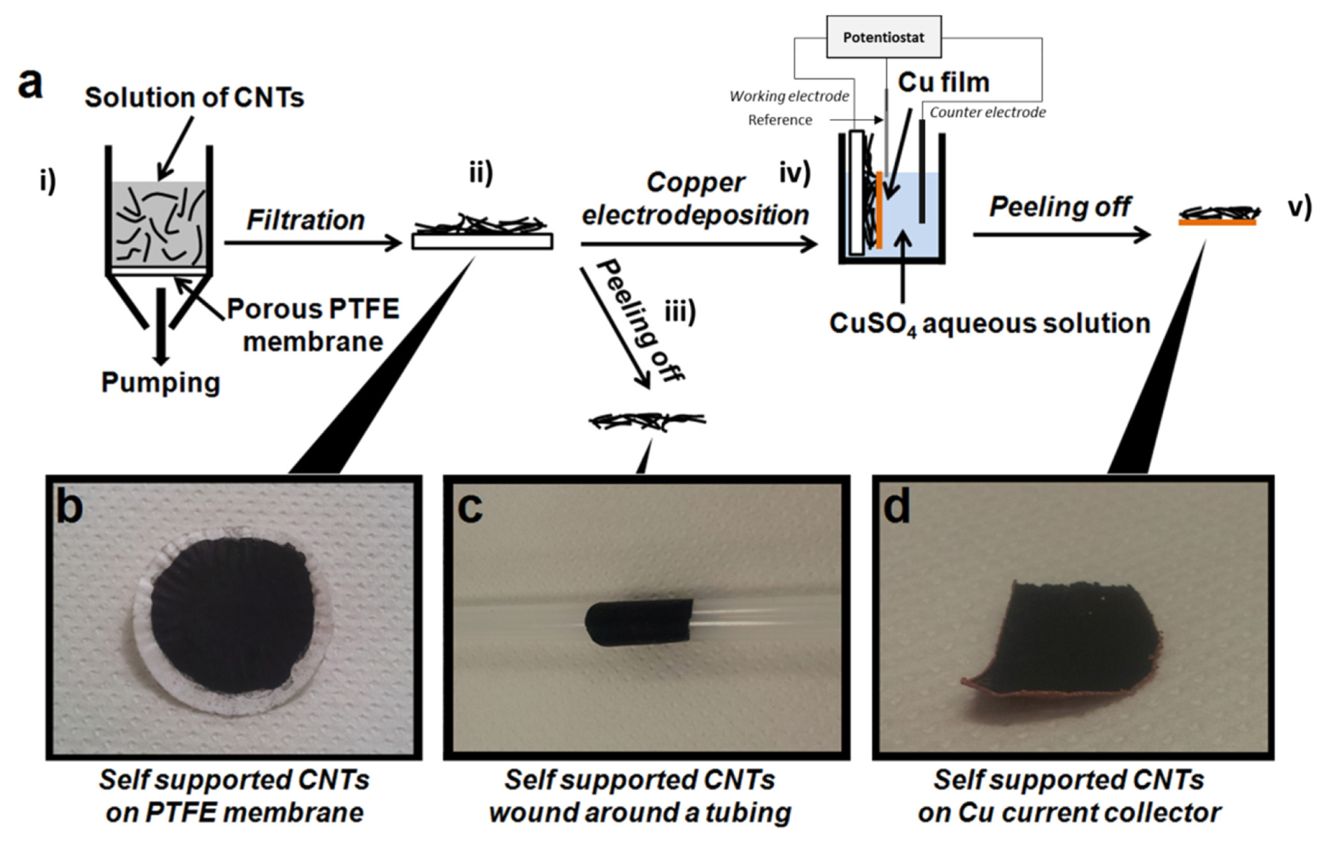
(a) Schematic representation of the preparation of the CNTs negative electrodes. A CNT film can be obtained by peeling off the film from the PTFE membrane, with or without an electrodeposition of Cu on the CNTs. (b) Photograph of the CNT film on the PTFE membrane. (c) Photograph of a CNT film. (d) Photograph of a self-supported CNTs film with the Cu current collector on the backside.
In order to deposit a copper current collector on the backside of a CNT film, the following steps were done. At first, a CNT film deposited on a PTFE membrane was placed in a three electrodes electrochemical cell (Fig. 1-a-iv) in which the working electrode was the CNT film. On the other hand, a platinum wire served as the pseudo-reference electrode, and a platinum foil served as the counter-electrode. Secondly, a copper electroplating solution was prepared being composed of 10 mM CuSO4 and 1.8 M H2SO4 (H2SO4 98%, Alfa Aesar®). The current density for the Cu deposition was regulated at 1 mA.cm−2 and fixed for 2 hours at room temperature. Thereafter, once the Cu electrodeposition was achieved, the sample was rinsed thoroughly with deionized water and then dried under a flow of nitrogen gas. Finally, the mechanical peeling-off allowed us to obtain the final CNTs film with a Cu backing (Fig. 1-d: Hereafter, we label the CNTs films with and without a Cu backing as CNT-Cu and CNT-NB, respectively).
For both CNT-NB and CNT-Cu films, the mass of CNTs is estimated to be 1.83 mg.cm−2. Only the mass of CNTs serves to determine capacities. Before storing in a glove box, CNTs films were dried at 65°C under vacuum for 48 hours. Electrochemical half-cells were prepared in an argon-filled glove box (water and dioxygen contents below 10 ppm). The model of the coin cells is 2032 model, later on, these cells were built with two electrodes, the first being the working electrodes (CNTs-based films) and the second counter electrodes (lithium foils). These electrodes were separated by a polypropylene membrane (Celgard® 2400) and a glass microfiber membrane (Whatman® GF/C) that was impregnated with 1 M LiPF6 dissolved in a 1:1:3 (v/v) mixture of ethylene carbonate (EC), propylene carbonate (PC) and dimethyl carbonate (DMC) from Novolyte®. Galvanostatic cycling was performed at different current densities with potential limits cut-off of 0.02 V and 2 V. All electrochemical measurements were made with a versatile multi-potentiostat (Biologic® VMP3). The morphology of prepared CNTs films was observed by a scanning electron microscopy (SEM; Zeiss® ULTRA Plus).
3. Results and Discussion
Morphology observations at low magnifications show a homogeneous surface for both CNT-NB and CNT-Cu films (Figs. 2-a and 2-d, respectively). More specifically, the CNT-NB film presents a better quality, whereas minor cracks are present on the surface of CNTs-Cu (Fig. 2-d). This observation would mean that the presence of the electrodeposited Cu current collector on the backside induces a mechanical rigidity to the self-supported CNT film. At higher magnifications, the morphologies appear to differ between CNT-NB and CNT-Cu films (Figs. 2-b and 2-e, respectively). The CNT-Cu film appears more compact and less porous than the CNT-NB. This observation is confirmed at the highest magnification (Figs. 2-c and 2-f) where the CNTs in the CNT-Cu film (Fig. 2-f) are compactly entangled. Taking into notice that the deposition step by filtration to prepare the CNT film on the PTFE membrane is the same for both prepared films, the difference observed in the film morphology was caused by the Cu electrodeposition step. As the deposition of the Cu current collector occurs in an aqueous solution for 2 hours, the hydrophobicity of CNTs would lead to its agglomeration, resulting in a higher apparent compactness of the film and a higher rigidity of the CNTs-Cu film in comparison with the CNT-NB film.
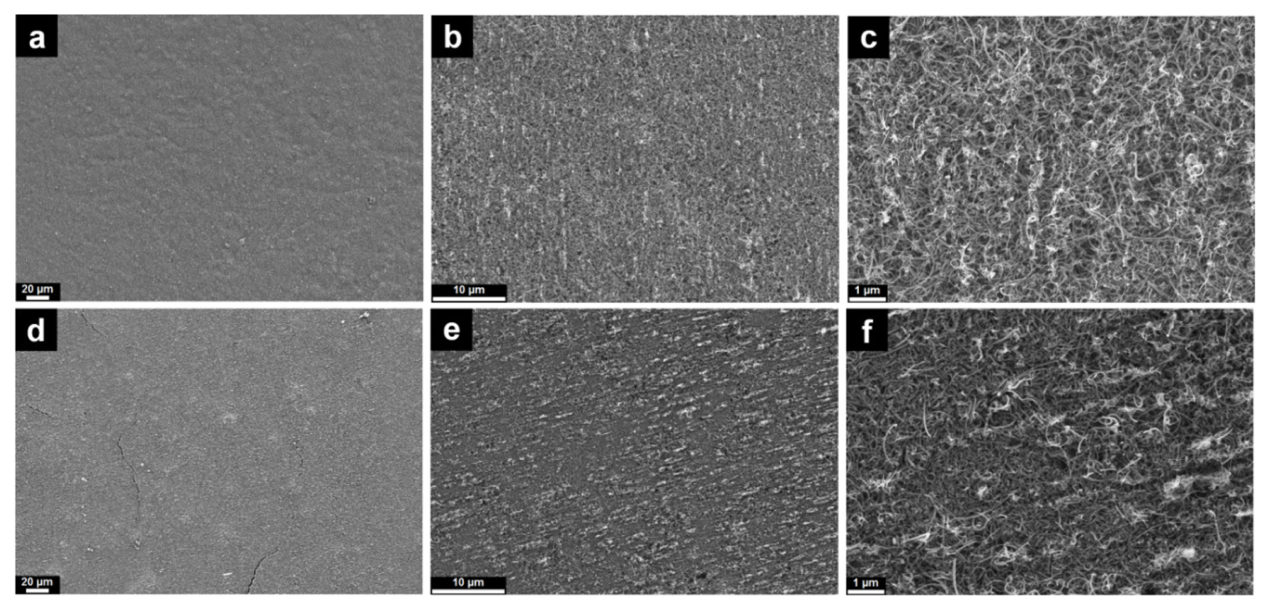
SEM images with different magnifications of CNT-NB (a,b,c) and CNT-Cu films (d, e, f).
The presence of the Cu current collector also affects the electrochemical behavior of the CNT films as electrodes in CNTs/Li half-cells. Galvanostatic profiles of the first charge (lithiation of CNTs) and discharge (de-lithiation) at a rate of C/20 are presented in Figs. 3-a and 3-b for CNTs without and with Cu current collector, respectively. Current rates are established referring to the gravimetric capacity of graphite with 1C = 372 mA/g. In the absence of Cu on the backside of the CNT film, the capacity reaches 693 mAh/g during the first charge at a rate of C/20 (Fig. 3-a). The profile of the first charge at C/20 (19 mA/g) presents two main plateaus located at the potential value of 1.5 V and of 0.85 V vs. Li/Li+. These reactions would be attributed to irreversible reactions taking place. The first plateau would be the irreversible reduction of oxygenated carbonaceous species present on the CNTs [19]. The second plateau at 0.85 V is attributed to the decomposition of the electrolyte forming the solid electrolyte interface (SEI). At potentials lower than 0.85 V, the charge curve makes a slope until the potential reaches its limit, which was fixed at 0.02 V. The absence of a slope is typical for the intercalation of lithium ions between the carbon layers in CNTs and this lithiation reaction is mainly reported to be effective below 0.1 V vs. Li/Li+. Noticeably, the lithium ions storage sites are located in defected sites such as cavities and pores of CNTs, and since they present a heterogeneous morphology, these lithiation sites are found in different shapes and dimensions. Hence, lithiation occurs in different electrochemical environments and thus the lithiation of CNTs could occur at closely but different potentials, inducing the absence of a slope for the lithiation of CNTs [20]. The first discharge shows a capacity of 146 mAh/g. As for the discharge (de-lithiation of CNTs), the first reaction occurs at a potential range between 0.02 to 0.25 V, and this reaction is attributed to de-intercalation of the lithium ions from the carbon layers. An additional reaction located at a potential of 1.1 V could be attributed to the quasi-reversible interaction between Li+ and oxygenated functional groups present on the CNT’s surface. The first coulombic efficiency is 21%. In comparison with the graphite anode, this low value of the coulombic efficiency is due to a larger effective surface of the CNT materials. For subsequent cycles, charge curves show the disappearance of plateaus attributed to irreversible reactions. These observations suggest that the formation of the SEI is stable from the first charge. The capacity values of the 2nd and 5th charges are 170 and 152 mAh/g,, while the capacity values of the 2nd and 5th discharges are 141 and 139 mAh/g, thus leading to coulombic efficiencies of 82% and 91%, respectively.
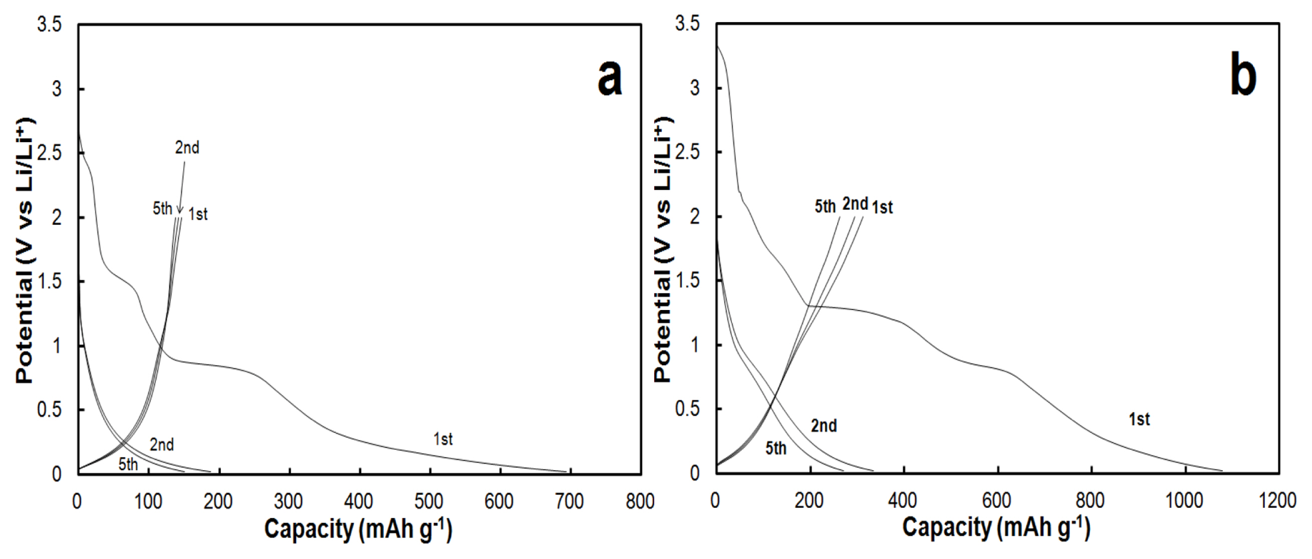
Galvanostatic profiles of the 1st, 2nd and 5th cycles for a) CNT-NB and b) CNT-Cu
Galvanostatic profiles for CNT-Cu are displayed in Fig. 3-b. During the first charge, typical irreversible reactions for CNTs materials are present at 1.5 V and 0.85 V, similarly in the case of CNT-NB (Fig. 3-a). In contrast to CNT-NB, additional reactions appear at potentials of 2.0 V and 1.3 V. These reactions would be attributed to the reduction of copper oxide following these equations 1 and 2:
Copper oxide species are present at the surface of the electrodeposited current collector. However, the capacity at 1.3 V is five times higher than that at 2.0 V (200 mAh/g and 40 mAh/g, respectively). The plateau/slope observed at 1.3 V would be also attributed to the reduction of residual adsorbed H2SO4 species at the CNT surface.
Indeed, the presence of these residual species may be due to the prolonged time (2 hours) during the electroplating bath used for the Cu deposition. Lithiation of CNTs occurs at potentials below 0.85 V, similarly in the case of the self-supported CNTs film without copper. The first charge capacity value is 1078 mAh/g, this high value is the specific capacity of the charge obtained in the first cycle which is mainly due to irreversible reactions taking place such as the ones formatting the SEI (from the reduction of the electrolyte) and the reduction of oxygenated species [10–12,19,21]. For subsequent charges, the decomposition of the electrolyte is still present at potentials values of 0.8 V, in contrast to CNT-NB. Due to the higher apparent compactness of CNTs in CNT-Cu compared to CNT-NB, the penetration of the electrolyte among CNTs of the film would not be very effective during the first cycles in the case of CNT-Cu. This would suggest that the SEI formation is possible on the surfaces of CNTs, which was not in contact with the electrolyte at previous cycles. Concerning the first discharge (de-lithiation of CNTs) as for CNT-NB, a first reaction is located in potential windows between 0.02 and 0.25 V due to the deintercalation of the lithium ions from graphitic carbon layers. The second reaction at 1.0 V could be attributed to the quasi-reversible interaction between Li+ and oxygenated functional groups present on the CNT surface. In contrast to the CNT-NB, an additional reaction is present at a potential of 1.55 V. This reaction would be attributed to the inverse reaction of Eq. 1:
The reaction of Eq. 2 is also reversible but at a potential of 2.5 V, which is higher than the upper potential limitation held during these galvanostatic cycling (i.e. 2 V). During the first galvanostatic cycle, the specific capacities of the charge (lithiation) and the discharge (de-lithiation) are 1078 mAh/ g and 311 mAh/g, respectively, denoting a coulombic efficiency of 29%. The second cycle presents a specific capacity of 334 mAh/g for the charge, and 294 mAh/g for the discharge, denoting a coulombic efficiency of 88%. Concluded form the specific capacities measured during lithiation for the first and the second cycles, the irreversible capacity is 744 mAh/g. As the electrode area of a CNT film is larger compared to a graphite electrode, this value is higher than the irreversible capacity usually observed on graphite electrodes [22]. Such an irreversible capacity is typical of CNTs anodes and has been already reported by other groups.
Prolonged galvanostatic cycling performed on a CNT-NB film between 0.02 and 2 V vs Li/Li+ at different current rates (Fig. 4). A current rate of C/20 (19 mA/g) is applied for the first five cycles and the discharge rate is equal to the charge rate, Dc/20 corresponding to 19 mA/g. We observed that the first coulombic efficiency is low with a value of 21%. Discharge capacities readily stabilize from the 2nd cycle to the 5th cycle at a capacity of 139 mAh/g for the 5th discharge. The coulombic efficiencies increase from 83% for the 2nd cycle to 91% for the 5th cycle. Increasing the current rates for both charge (lithiation) and discharge (de-lithiation) at C/10 = Dc/10 (37 mA/g) and C/5 = Dc/5 (74 mA/g), we observed that the discharge capacity is also stabilized at each rate, with discharge capacity values of 131 mAh/g at Dc/10 and 119 mAh/g at Dc/5. Meanwhile during the 15th cycle, the coulombic efficiency reaches a value of 99%. At higher current rates, C2 = Dc/2 (186 mA/g), 1C = 1Dc (372 mA/g), 2C =2Dc (744 mA/g) and 5C = 5Dc (1860 mA/g), we observed that the discharge capacities are not stabilized within the 5 cycles of each different rates, whereas the coulombic efficiencies are above 99.5%. When increasing the charge rate from C/10 to 5C, we observed a drop in the capacities due to the not so well defined potential, where the lithiation of CNTs can be efficient (Fig. 3-a). The lithiation of CNTs would be the limiting factor to reach higher capacities for CNTs-based negative electrodes. Considering this observation, a charge rate of C/10 (37 mA/g) was kept constant between the 36th and the 60th cycle, but with an increase of the discharge rate. In this case, the discharge capacities are 143 mAh/g at Dc/10, 140 mAh/g at Dc/2, 138 mAh/g at 1Dc and 2Dc, and 132 mAh/g at 5Dc. From the 61st to the 85th cycle, the current rate for the charge was kept constant at C/5 (74 mA/g). Here, the discharge capacities are 137 mAh/g at Dc/5, 136 mAh/g at Dc/2, 136 mAh/g at 1Dc, 135 at 2Dc, and 134 mAh/g at 5Dc.
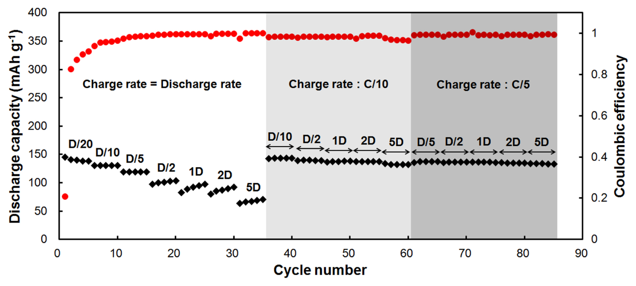
Discharge capacities and coulombic efficiencies of a CNT-NB film
Galvanostatic cycling also performed on a CNT-Cu film between 0.02 and 2 V vs. Li/Li+ at different current rates (Fig. 5). To observe the effect of the current collector on the electrochemical performance, we ran a similar method for the galvanostatic cycling. During the first stage of the experiment and specifically from the 1s t to the 35th cycle, an equivalent current rate was applied for both charge and discharge. In contrast to CNT-NB, we observe that capacities are not stabilized within the first five cycles at C/20, with values of 308 mAh/g for the 1st discharge and 264 mAh/g for the 5th discharge. Coulombic efficiencies after the first cycle are 29%, whereas it is 97% after 5th cycle. At a C/10 regime, capacities are not well stabilized, showing a slight decline from 239 to 229 mAh/g between the 6th and 10th cycles. Further increase in both charge and discharge rates, a drop of the capacities is observed as each rate increases, but within the 5 cycles running at the same rate, a slight increase of the capacity is observed. Comparing the performances obtained with CNT-Cu and CNT-NB films, discharge capacities are higher for the CNTs film in presence of a metallic current collector. At the end of each 5 cycles with Dc/5, Dc/2, 1Dc, 2Dc, and 5Dc, the discharge capacities are 205, 179, 164, 143, and 109 mAh/g, respectively. Then subsequent 25 cycles were performed at a constant charge rate of C/10 and at different current rates for the discharge. Discharge capacities at Dc/2, 1Dc, 2Dc, and 5Dc are higher in this case than the discharge capacities obtained when rates for charge and discharge are equal. Moreover, at each rate, the discharge is completely stabilized. The values of the discharge capacities are 205 mAh/g at Dc/2, 200 mAh/g at 1Dc, 192 mAh/g at 2Dc mAh/g and 183 mAh/g at 5Dc. When the charge rate is constant and fixed at C/5 for the subsequent 25 cycles, the behavior of the electrochemical performances is similar, along with a stabilization of the discharge capacities at different discharge rate. For a discharge with Dc/5, Dc/2, 1Dc, 2Dc, and 5Dc, the capacities reached were 214, 207, 199, 193, and 183 mAh/g, respectively. From galvanostatic cycling, we generally observed that the electrochemical performances in terms of capacities values are higher when the electrodeposited Cu current collector is present on the backside of the CNT film.

Discharge capacities and coulombic efficiencies of a CNT-Cu film.
Fig. 6 displays the electrochemical impedance spectra (EIS) of CNTs films with and without copper. The EIS spectra were recorded at the end of the discharge (de-lithiation) cycles; therefore, the SEI layer was already formed on the electrodes. The EIS spectra are typical of a lithium insertion anode and it consists of two overlapping semi-circles at high frequencies followed by a sloping line at lower frequencies. The presence of more than one semi-circles in an EIS spectrum could indicate that more than one interfaces were formed [23]. Moreover, since the spectra were collected at the end of the discharge (2 V vs. Li), the semi-circles are not assigned to the charge transfer reaction of the lithium insertion. The semi-circles could be ascribed as the contribution of the interface resistance between current collector and CNTs film, and/or contact resistance among CNT particles (1.3 kHz), and the SEI layer resistance (274 Hz), while the sloping line is attributed to the diffusion of the lithium ions in the bulk of the materials. Regardless of the presence or absence of the copper, the characteristic frequencies of the semi-circles (frequencies at the top of the semi-circles) are similar, but their diameters vary and thus their corresponding impedances are completely different. The integration of the electrodeposited copper current collector drastically decreases the high frequencies impedance. This could indicate that CNT-Cu electrode exhibits a lower contact impedance by comparison to the Cu-free electrode. Moreover, the semi-circle at 274 Hz, which is assigned to the SEI layer, is larger in the case of CNTs without copper. As for all lithium insertion anodes, the SEI layer is originated from the irreversible reduction of the electrolyte during the first charge and its value is proportional to the accessible surface of the electrode. Therefore, we can expect that without Cu-current collector the CNTs are more exposed to the electrolyte. This statement is supported by SEM images of Fig. 2, which confirm that the CNTs are more entangled/compacted in the presence of electrodeposited copper. Moreover, at low frequencies, the CNT-Cu electrode shows 45° sloping line that reflects a restricted diffusion process represented by the well-known Warburg impedance contrasting with the less sloping line in the case of the electrode without electrodeposited copper. In the same way, by considering the serial equivalent impedance (ESR1 and ESR2 in Fig. 6), determined from the intersection of the extrapolation of the lines at low frequencies with real axis of impedance, one can conclude that integration of the Cucurrent collector decreases drastically the electrode’s impedance.
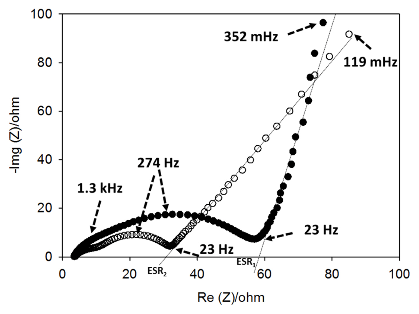
EIS spectra of CNT-Cu (○) and CNT-NB (●) anodes.
4. Conclusions
We have demonstrated that the integration of a copper current-collector to a binder-free and self-supporting CNTs film leads to a lithium anode assembly with improved performances by comparison to the collector-free electrode. The current collector has been generated by electrochemical deposition on the backside of the CNT film. The CNT-Cu assembly showed a reversible capacity of 229 mAh/g at C/10 and 192 mAh/g at high discharge rate 5C. The method reported herein is simple and allows integration of the current collector onto self-supporting electrode while maintaining their flexibility.
Acknowledgement
This work was supported by Region Centre, France, through the BLaDES and the μBaGs projects.