Synthesis of CoSe2/RGO Composites and Its Application as a Counter Electrode for Dye-Sensitized Solar Cells
Article information
Abstract
In this study, cobalt diselenide (CoSe2) and the composites (CoSe2@RGO) of CoSe2 and reduced graphene oxide (RGO) were synthesized by a facile hydrothermal reaction using cobalt ions and selenide source with or without graphene oxide (GO). The formation of CoSe2@RGO composites was identified by analysis with X-ray diffraction (XRD), X-ray photoelectron spectroscopy (XPS), Raman spectroscopy and scanning electron microscopy (SEM). Electrochemical analyses demonstrated that the CoSe2@RGO composites have excellent catalytic activity for the reduction of I3−, possibly indicating a synergetic effect of CoSe2 and RGO. As a consequence, the CoSe2@RGO composites were applied as a counter electrode in DSSC for the reduction of redox couple electrolyte, and exhibiting the comparable power conversion efficiency (7.01%) to the rare metal platinum (Pt) based photovoltaic device (6.77%).
1. Introduction
Since the breakthrough work by Grätzel and O’Regan in 1991, dye-sensitized solar cells (DSSCs) have been formulated like a sandwich configuration that consists of photoanode, electrolyte, and counter electrode (CE) [1]. Unlike silicon-based solar cells, electrons generated by light illumination in DSSCs are transported via electrochemical reactions, and thus called electrochemical devices. In specific, Pt is the most widely used material as the catalyst for the reduction of redox couple electrolyte of DSSCs due to its superior electrocatalytic properties and chemical stability against an iodide/triiodide (I−/I3−)-based electrolyte [2].
A lot of efforts have been devoted to develop alternative catalytic materials for expensive rare metal platinum (Pt) [3–4]. Although cost-effective carbon-based materials including carbon black, carbon nanotube, graphite, and graphene have exhibited stable chemical stability, unique structural features, and electronic properties, they do not possess catalytic activities as high as Pt [5–6]. Recently, metal chalcogenide (MC) materials have emerged as a potential candidate for the electrochemical and catalytic applications [7]. The MCs have a composition of MX, where M= a transition metal, X= chalcogen (S, Se, and Te), and their physical and chemical properties vary according to the sort of M and X. MCs have been utilized in a wide range of fields such as transistors, energy conversion, and storage devices [8]. Many kinds of MCs have been also applied to DSSCs as the catalyst materials for the reduction of redox couple electrolyte [9]. Cobalt sulfide (CoS) was employed as a CE material of DSSCs for the first time by Wang et al. [10], exhibiting similar electrocatalytic effects like Pt, and low charge transfer resistance corresponding to 1.8 Ωcm2. After that, FeS2 [11], Ni0.85Se [12], NiSe2 [13], and other MCs have been used to catalyst materials for the CE of DSSCs whose devices showed superior performances with low charge transfer resistance. Here, we have scrutinized RGO and cobalt diselenide (CoSe2), which are broadly suited in catalysis research. They are highly sensitive to catalytic reaction and conductive to deliver carries to optimal sites. They are also very cheap and easily scalable when industrial demands are existing.
In this study, CoSe2 and the composites (CoSe2@RGO) of CoSe2 and reduced graphene oxide (RGO) were synthesized by a facile hydrothermal reaction using cobalt ions and selenide source with or without graphene oxide (GO). CoSe2 supported by carbon derivatives has been studied as a prospective material for rechargeable aluminum-ion batteries (RAIBs) [14] and catalyst for the oxygen reduction reaction [15], exhibiting good catalytic effects and stability. Herein, the composite of CoSe2@RGO is utilized as the CE of DSSCs for I3− reduction. Electrochemical analyses demonstrated that the CoSe2@RGO composites have excellent catalytic activity for the reduction of I3−, possibly indicating a synergetic effect of CoSe2 and RGO. As a consequence, the CoSe2@RGO composites based devices exhibited comparable power conversion efficiencies (7.01%) to the rare metal platinum (Pt) based photovoltaic device (6.77%).
2. Experimental
2.1 Synthesis of CoSe2, CoSe2@RGO and RGO
CoSe2 was synthesized via a facile hydrothermal reaction. Selenium (Se) precursor solution (solution A) was prepared by dissolving 4 g of sodium hydroxide (NaOH, Aldrich, 99% anhydrous) in 30 ml of deionized water (DI water) followed by adding 0.32 g of selenium powder (Se, Aldrich, 99.999% metal basis) at 80°C to dissolve Se, completely. Cobalt (Co) precursor solution (solution B) was prepared by dissolving 0.31 g of ethyldiaminetetraacetic acid disodium salt dihydrate (EDTA-2Na, Sigma-Aldrich, 99.0–101.0%) in 10 ml of DI water with vigorous stirring for a few minutes followed by adding 0.48 g of cobalt chloride hexahydrate (CoCl2·6H2O, Alfa Aesar, 99.9% metal basis). After heating the solution B at the same temperature of the solution A, the solution B was slowly poured into the solution A, and the mixed solution was further stirred for 10 min on a heated hot plate. Then, the precursor solution was transferred to a Teflon-lined autoclave, and heated at 170°C for 12 h. After cooling down to room temperature naturally, the black precipitate was obtained and washed several times with water and ethanol. Finally, the product was dried in a vacuum oven at 60°C for overnight.
In the case of CoSe2@RGO, the whole synthesis procedure was similar to CoSe2 synthesis but a solution C was added. 2.6 mg of graphene oxide (GO) sheets was uniformly dispersed by ultra-sonication in 8 ml of DI water to form the solution C.
To compare the CoSe2@RGO composites, RGO was also synthesized by using a hydrothermal method. 30 mg of GO in 60 ml of DI water was treated in an ultrasonic bath for 30 min and the dispersed solution was transferred to an autoclave. The hydrothermal reaction was conducted at the same condition for the synthesis of cobalt diselenide derivatives. The precipitation was washed several times, then completely dried at 60°C.
2.2 Preparation of TiO2 photoanode
Fluorine-doped tin oxide (FTO) glass substrates (TEC, 8 Ω, Pilkington) were cleaned with a detergent solution and then cleaned in an ultrasonic bath using ethanol, acetone, and 2-propanol for 10 min, respectively. After UV-treatment for 20 min, TiO2 paste (ENB Korea, 20 nm) was coated on the substrates by a doctor-blade method. The resulting layer was sintered at 500°C for 2 h in a muffle furnace. The TiO2-coated substrates were immersed in 0.3 mM of an N719 dye solution (a mixture of tert-butanol and acetonitrile in a volume ratio of 1:1) for 24 h at room temperature.
2.3 Preparation of counter electrode
CoSe2 and CoSe2@RGO powder were dispersed in γ-butyrolactone (GBL, Sigma-Aldrich, 99%) at a 0.7 mg/ml, 1.3 mg/ml and 2 mg/ml concentration. Then, the dispersion was drop-casted onto UV-cleaned 3 cm × 4 cm size FTO glass at the amount of 10 μg/cm2, 20 μg/cm2 and 30 μg/cm2. The substrates were dried in an ambient condition naturally for overnight and then thermal treated at 200°C for several minutes. For the comparison, RGO powder was also dispersed in GBL at a 1.3 mg/ml concentration. The subsequent process was the same as the preparation of CoSe2 with/without RGO CE. In the case of the platinized CE, 7 mM of chloroplatinic acid hexahydrate (H2PtCl6, Sigma-Aldrich) solution in 2-propanol (IPA) was prepared and the solution was drop-casted onto the FTO substrates, and then sintered at 400 °C for 1 h. The final loading amount of Pt and RGO was fitted at 20 μg/cm2.
2.4 Device fabrication
Treated 3 cm × 4 cm size anode and cathode were cut into 1.5 cm × 2.0 cm. Two kinds of electrodes were combined using hot-melt Surlyn (Solaronix, 60 μm) spacer. After that, iodide/triiodide redox shuttle electrolyte was injected through a pre-drilled hole and the holes were sealed by a thin cover glass. The electrolyte composition was 1-hexyl-2,3-dimethylimidazolium iodide (0.6 M), iodine (0.03 M), guanidinium thiocyanate (0.1 M), and 4-tert-butylpyridine (0.5 M) in acetonitrile.
2.5 Characterization
X-ray diffraction measurement was carried out using a Cu Kα radiation (λ = 0.154 nm) (D8 Advance, Bruker). Scanning electron microscopy (SEM) images of CoSe2 and CoSe2@RGO were taken using FESEM (FE-SEM, Hitachi S-4800 and Nova NanoSEM 230). Raman spectra were obtained using micro-Raman spectrometer (Alpha 300R) excited at 633 nm laser source. Surface chemical state were investigated using X-ray photoelectron spectroscopy (XPS, K-alpha, Thermo Fisher). Electrochemical impedance spectroscopy (EIS) and Tafel polarization measurements were performed with symmetrical dummy cells, which were filled with the same electrolyte used in DSSCs. EIS were conducted in a frequency range of 10−1 to 106 Hz, The Nyquist plot were fitted using Z-view software. Cyclic voltammetry (CV) measurements were carried out in a three-electrode using a Pt-mesh as a CE and a Ag/Ag+ electrode as a reference electrode in a electrolyte solution (0.1 M of LiClO4, 0.01 M LiI, and 1 mM I2 in acetonitrile). Current density-voltage (J-V) curves of DSSCs with different CEs were obtained using potentiostat under 100 mW/cm2 AM 1.5G light (ABET Technology, LS 150 simulator). All the electrochemical characterizations were performed with electrochemical station (Bio-Logic, VSP).
3. Results and Discussion
To characterize the phase and structures of the assynthesized materials, X-ray diffraction (XRD) measurements were performed on CoSe2@RGO, CoSe2, reduced graphene oxide (RGO), and graphene oxide (GO). The XRD patterns of GO exhibited a peak at 11.3°, corresponding to an interplanar spacing of 0.78 nm. The XRD patterns of the hydrothermal treated GO showed a broad peak of RGO at 23.1°, corresponding to an interplanar spacing of 0.38 nm. The XRD patterns of the as-synthesized CoSe2@RGO showed a peak of RGO at 23.1°. Moreover, the peak intensities of the CoSe2@RGO became weak, and the phase intensities were changed, compared to the pure CoSe2, suggesting that the RGO have an effect on the formation of CoSe2, and possibly mixed via hydrothermal reaction [16]. The XRD patterns of the as-synthesized CoSe2 and CoSe2@RGO were compared to the standard XRD data of CoSe2 (JCPDS no. 00-053-0449) in Supporting Information (SI) Fig. S1. To compare the morphology of CoSe2 and CoSe2@RGO, SEM image characterization were conducted on the samples shown in Fig. S2. The synthesized CoSe2 has tiny nanorod-based shape, while CoSe2@RGO has another kind of CoSe2 crystal like sheet shape with tiny nanorod-based CoSe2.
To further confirm that an RGO phase in the CoSe2@RGO composite, we performed Raman characterization on the CoSe2 and CoSe2@RGO. The Raman spectra of the CoSe2 and CoSe2@RGO are shown in Fig. 1b. The peak at 171 cm−1 in both samples represents the bending of Se-Se bonds in the close-packed chains [17]. By contrast, the CoSe2@RGO sample contains two peaks at 1328 and 1587 cm−1. These peaks are known as defect band (D-band, 1328 cm−1), and graphitic band (G-band, 1587 cm−1), which are usually observed in GO and RGO. The intensity of D-band to G-band (ID/IG) observed in the CoSe2@RGO exhibited 1.10 of ID/IG, which implies that GO was converted into RGO via hydrothermal reaction with the formation of CoSe2 compounds [18]. X-ray photoelectron spectroscopy (XPS) measurements were performed on the as-synthesized CoSe2 and CoSe2@RGO. Fig. 1c represents the XPS spectra for Co 2p, and Fig. 1d does for Se 3d. The XPS spectra peaks correspond to Co 2p3/2 at 778.5 eV, Co 2p1/2 at 793 eV, Se 3d5/2 at 54.6 eV, and Se 3d3/2 at 55.3 eV, respectively [19].
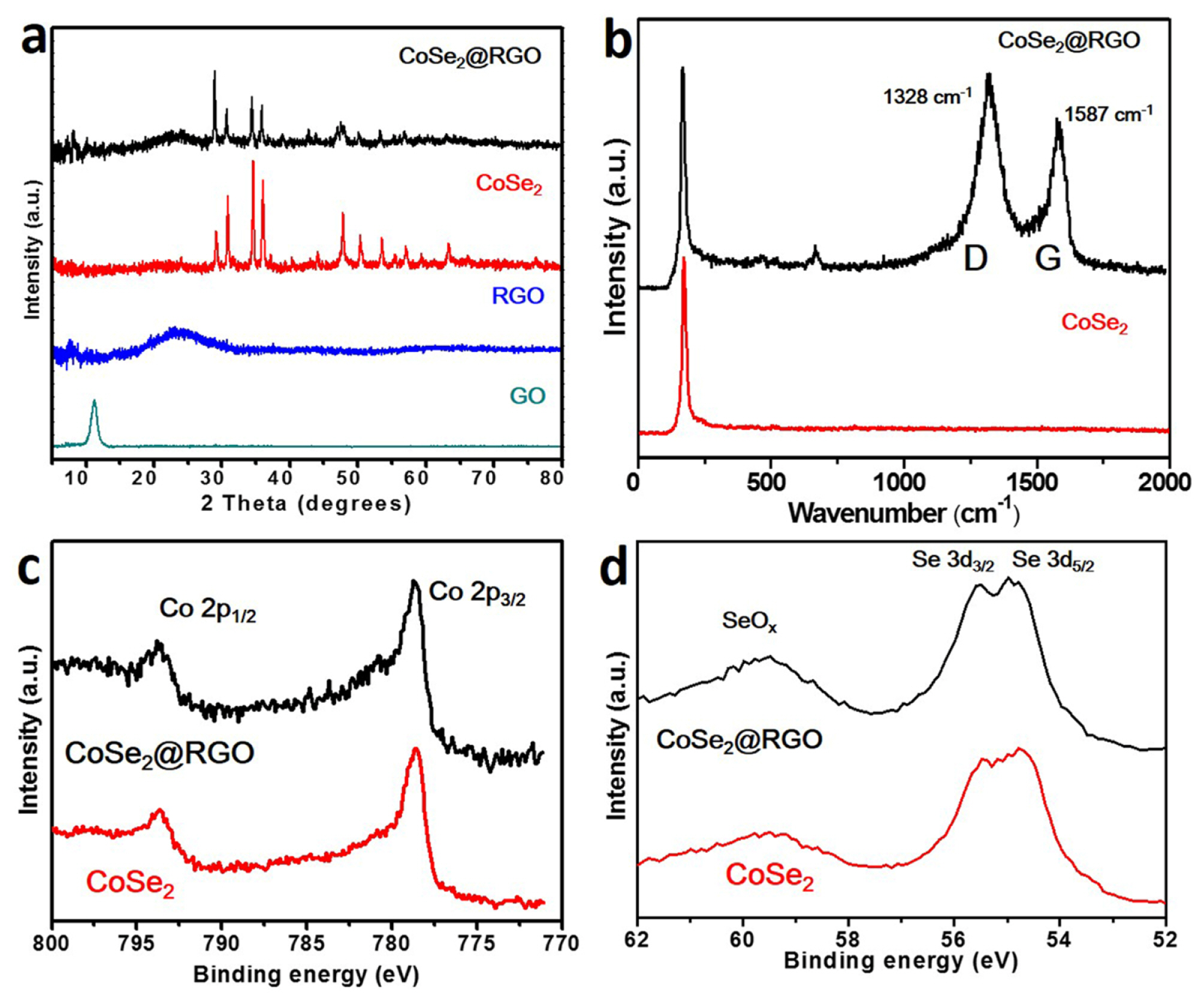
(a) X-ray diffraction patterns of CoSe2@RGO, CoSe2 RGO, and GO. (b) Raman spectra of CoSe2@RGO, and CoSe2. X-ray photoelectron spectroscopy spectra for (c) Co 2p and (d) Se 3d of CoSe2@RGO and CoSe2.
These results are well consistent with reported CoSe2 [19]. Fig. 2 demonstrates the XPS spectra of GO, RGO, CoSe2, and CoSe2@RGO for C 1s. In the case of RGO, the peaks related to oxygen bond significantly decreased compared to GO, pointing out that a large number of functional groups associated with oxygen were removed via hydrothermal reaction, and thus converted to RGO [16]. In addition, the C-O peaks at around 286.6 eV in CoSe2@RGO were not as strong as the GO sample, which proves that GO in the CoSe2@RGO were converted to RGO via hydrothermal reaction. Also, the relative peak intensity of carbon-carbon bond for the CoSe2@RGO is higher than the CoSe2, On the other hand, the intensity of Co and Se is similar in both samples. It is evident from the results that the CoSe2@RGO is surely composed of carbon derivatives that have a less of carbon-oxygen bond groups.
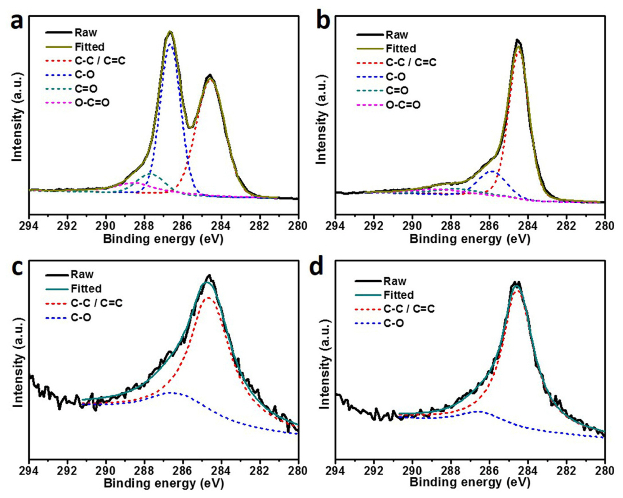
X-ray photoelectron spectroscopy spectra of (a) GO, (b) RGO, (c) CoSe2, and (d) CoSe2@RGO for C 1s.
To investigate catalytic performances of the assynthesized materials, electrochemical analyses were conducted with F-doped SnO2 (FTO) electrodes coated of Pt, RGO, CoSe2, and CoSe2@RGO. Cyclic voltammetry (CV) curves of various samples can be found in Fig. 3a. Two pairs of the peaks corresponding to the oxidation and reduction of iodide (I−) and triiodide (I3−) were observed [20], the oxidation and reduction reaction of the I species are given in eqn (1) and (2):

(a) Cyclic voltammetry curves of Pt, CoSe2, CoSe2@RGO, and RGO scanned at a rate of 50 mV/s. (b) Nyquist plots for symmetric dummy cells of Pt, CoSe2, CoSe2@RGO, and RGO. The inset shows the corresponding Nyquist plots at a magnified scale. (c) Tafel polarization curves for symmetric dummy cells of Pt, CoSe2, CoSe2@RGO, and RGO scanned at a rate of 10 mV/s and (d) magnified cathodic branches.
The difference between the voltages of the left pair peaks was compared to evaluate the catalytic performance in DSSCs of materials. The peak-to-peak separation (Epp) of the left pair for the Pt, CoSe2, and CoSe2@RGO based electrodes was 0.639 V, 0.585 V, and 0.432 V, respectively. The Epp of the RGO based electrode was not clearly determined owing to the ambiguousness of its reduction peak from I3− to I−. The CoSe2@RGO based electrode that shows the lowest Epp values exhibited better electrocatalytic performances than the others.
Electrochemical impedance spectroscopy (EIS) measurement was performed to examine the interfacial electrochemical properties, using symmetric dummy cells of the as-synthesized materials. Nyquist plots of Pt, RGO, CoSe2, and CoSe2@RGO are illustrated in Fig. 3b. The first semicircles of the plots present the charge transfer resistance (Rct) at the electrodes/electrolyte interface. Thus, Rct is directly linked to the electrocatalytic effects of materials and the number of catalytic sites. The Rct of the Pt, RGO, COSe2, and CoSe2@RGO based devices was 0.61 Ωcm2, 64.75 Ωcm2, 0.50 Ωcm2, and 0.20 Ωcm2, respectively, indicating that the CoSe2@RGO preserves more active catalytic sites for I3− reduction [12]. The second semicircle at low-frequency region arising from Nernst diffusion impedance (or Warburg impedance, Zw) of the electrolyte species had the value of 1.90 Ωcm2 for Pt, 3.12 Ωcm2 for RGO, 1.36 Ωcm2 for CoSe2, and 1.75 Ωcm2 for CoSe2@RGO. In the consideration that Zw decreases when the diffusion co-efficient (DI) of I3− increases, the CoSe2 based electrodes have the superior electrocatalytic activity to the Pt based electrode. Equivalent circuit and fitted results for the EIS measurement are provided in Fig. S2.
To further elucidate the electrocatalytic activity of the as-synthesized materials, Tafel polarization measurement was conducted with the symmetric cells. Fig. 3c shows the Tafel polarization curves. The slope of Tafel zone at the middle potentials with a sharp slope can be considered as exchange current density (J0) [10]. The J0 can be derived from the function of Rct, as described in the following eqn (3):
Where R is the gas constant, T is the absolute temperature, n is the number of electrons involved in the reduction of I3− to I−, and F is Faraday’s constant. Thus, the slope of the Tafel zone is inversely correlated to Rct, and the slopes of the Pt, RGO, CoSe2, and CoSe2@RGO based devices revealed that the CoSe2@RGO based device shows a superb charge-transfer performance compared to the control group, which is consistent with the result of the EIS analysis.
The DI of I3- reduction in the redox couple can be expressed with the limiting current density (Jlim) at the high voltage zone with the y-axis [21], which is derived from the following eqn (4):
Where n is the number of electrons involved in the reaction, F is Faraday’s constant, l is the spacer thickness, and C is the I3− concentration. The result from the Jlim is consistent with that from the Zw, which was obtained from the EIS analysis. This Tafel polarization study revealed that the CoSe2 and CoSe2@RGO based CE have the comparable electrocatalytic performance to the Pt based CE in the reduction process of I3− to I− of the redox couple.
Fig. 4 shows the current density-voltage (J-V) curves of DSSCs fabricated with counter electrodes of the as-synthesized materials measured under one-sun illumination, and their photovoltaic parameters are summarized in Table 1. The loading amount of the as-synthesized materials onto counter electrodes was adjusted by varying the precursor concentration. The summarized results of photovoltaic parameters according to the loading amount of catalyst materials are provided in Fig. S3. For all the electrodes, quite comparable catalytic reaction at the counter electrode was shown. However, RGO electrode showed very high series resistance which is appeared in FF value, and CoSe2 only electrode showed lower photovoltage than both of the materials are applied. Although clear reason is not given at this moment, advantages of both RGO and CoSe2 could be utilized when both of materials are combined. When the loading amount is increased to 30 mg/cm2, FF and current densities are lowered only to show lower performance. Loading of high concentration of the composite may cause their coming off the electrode, and this may affect electrolyte system. Similar phenomena are observed when carbon black composite has been applied [22].

Current density-voltage characteristics of dye-sensitized solar cells fabricated with different counter electrodes measured under one-sun illumination (100 mW/cm2).

Photovoltaic parameters of dye-sensitized solar cells fabricated with different counter electrodes. The loading amount of catalyst materials onto the counter electrode was fixed at 20 μg/cm2.
The DSSC of RGO based CE exhibited the lowest performances, mainly because of low fill factor (FF, 0.40), possibly connected to the high charge transfer resistance at the electrolyte/CE interface. On the other hand, the DSSC of CoSe2@RGO based CE represented the best efficiency (η) of 7.01% with an open circuit voltage (VOC) of 0.792, an FF of 0.72, and a short circuit current density (Jsc) of 12.24 mA/cm2, which is higher than the η of 6.77 % of the Pt based CE photovoltaic (Voc= 0.762 V, FF = 0.67 and Jsc = 13.12 mA/cm2). The enhanced parameters of DSSC were attributed to the superior electrocatalytic activity of the CoSe2@RGO, and these results suggest that the composites of CoSe2 with RGO can be a promising alternative material to the rare metal Pt.
4. Conclusions
In summary, we presented a facile approach to synthesize CoSe2@RGO composites using a hydrothermal reaction. The formation of CoSe2@RGO were confirmed by XRD, XPS, FE-SEM and Raman analyses. Electrocatalytic activities of CoSe2 derivatives were examined compared to rare metal Pt based counter electrode. Electrochemical analyses such as EIS, CV, and Tafel polarization demonstrated that CoSe2@RGO has excellent electrocatalytic effects for the reduction of triiodide (I3−) to iodide (I−) due to its low charge transfer resistance (Rct), which is lower than Pt based electrode device. DSSCs using the CoSe2@RGO material as a catalyst for the reduction of redox couple electrolyte exhibited a higher power conversion efficiency (PCE) of 7.01% than the Pt based device (6.77%) under one-sun illumination. We believe that the composites of CoSe2 with RGO are a promising alternative material to the rare metal Pt catalyst in a CE of DSSCs.
Supplementary Information
Acknowledgement
This research was supported by National Research Foundation of Korea, 2015M1A2A2056829, 2018M1A2A2058204, First-Mover Program for Accelerating Disruptive Technology Development (NRF-2018M3C1B9088457), Korea Institute of Energy Technology Evaluation and Planning (KETEP) and the Ministry of Trade, Industry and Energy (MOTIE, 20194010201900) and Korea Institute for Advancement of Technology (KIAT, N0002431).
Notes
Supporting Information
Supporting Information is available at https://doi.org/10.33961/jecst.2019.00052