Recent Progress on Sodium Vanadium Fluorophosphates for High Voltage Sodium-Ion Battery Application
Article information
Abstract
Na-ion batteries are being considered as promising cost-effective energy storage devices for the future compared to Li-ion batteries owing to the crustal abundance of Na-ion. However, the large radius of the Na ion result in sluggish electrode kinetics that leads to poor electrochemical performance, which prohibits the use of these batteries in real time application. Therefore, identification and optimization of the anode, cathode, and electrolyte are essential for achieving high-performance Na-ion batteries. In this context, the current review discusses the suitable high-voltage cathode materials for Na-ion batteries. According to a recent research survey, sodium vanadium fluorophosphate (NVPF) compounds have been emphasized for use as a high-voltage Na-ion cathode material. Among the fluorophosphate groups, Na3V2(PO4)2F3 exhibited the high theoretical capacity (128 mAh g−1) and working voltage (~3.9 V vs. Na/Na+) compared to the other fluorophosphates and Na3V2(PO4)3. Here, we have also highlighted the classification of Fluorophosphates, NVPF composite with carbonaceous materials, the appropriate synthesis methods and how these methods can enhance the electrochemical performance. Finally, the recent developments in NVPF for the application in energy storage devices and its outlook are summarized.
1. Introduction
Sodium ion batteries are considered as next generation energy storage devices instead of Li-ion batteries owing to the less availability of Li-ion source. However, there are two serious issues behind Na-ion batteries that affect the application of Na-ion batteries: one is the ionic size that hinders the Na ion diffusion into the crystal structure and the other is the higher potential compared to Li [1,2]. These two problems can be overcome by identifying suitable low-voltage anode and high-voltage cathode materials. In this context, we have focused on the high cell voltage cathode material for sodium ion batteries. Recently layered structure materials such as NaMO2 (M = Ni, Mn, Cr, Co and V) metal oxides [2–7], NASICON-type material [8,9], Prussian blue analogues [10–12], and co-polymers [13] have been investigated in detail as cathode material for Na-ion batteries due to their moderate specific capacity and cell voltage. Considering the layered structure, Bruce’s group have demonstrated the high electrochemical performance of β-NaMnO2, whose crystal structure consists of zigzag layers of edge-sharing MnO6 octahedra, with NaO6 octahedral residing in between these zigzag layers. β-NaMnO2 exhibits an average cell voltage of 2.7 V (vs. Na/Na+) and delivers a high capacity of 190 mAh g−1 at C/20 rate as well as excellent rate capability (90 mAh g−1 at 10C rate) [14]. Ceder’s group synthesized the three transition metals (O3- type NaNi1/3Co1/3Fe1/3O2) through one step solid state reaction which yielded a high reversible capacity of 165 mAh g−1 at C/20 rate while retaining a specific capacity of 80 mAh g−1 at 30C rate [15]. However, β-NaMnO2 and NaNi1/3Co1/3Fe1/3O2 show poor cycling stability and average cell voltage (~2.8 V vs. Na/Na+). Nevertheless, electrochemical performance of layered oxides can be improved by the substitution of Li ion at the transition metal sites [16–18]. In this regard, Sun’s group reported a high-capacity O3-type Na[Li0.05(Ni0.25Fe0.25Mn0.5)0.95]O2 cathode material for Na-ion batteries that delivers excellent capacity of 180 and 96 mAh g−1 at 0.1 and 5 C current rates respectively [18]. Recently, Prussian blue analogues and organic polymers have attracted great interest because of their high capacity and average operating voltage [19]. Lee et al. investigated the Na2MnII[MnII(CN)6] Prussian blue compound that showed an excellent capacity of 209 mAh g−1 at C/5 current rate and was mediated by a two-electron reaction; it revealed a reversible capacity of 167 mAh g−1 at 2C rate [20]. Apart from inorganic compounds, Yang’s group recently introduced the high-capacity aniline-nitroaniline copolymer that was synthesized through the chemical oxidative polymerization process that delivered a high specific capacity of 173 mAh g−1 at 40 mA g−1 over 50 cycles at an average voltage of 3.2 V vs Na/Na+ [21]. The reported layered material, Prussian blue analogue, and organic polymer exhibit moderate cell voltage and cycling stability [22].
In recent decades, polyanion based material such as phosphates, pyrophosphates, mixed phosphates, fluorophosphates, sulphates and carbonophosphates have widely investigated as cathode materials for Naion batteries because of the stability of their crystal structures and high potential, which can be attributed to inductive effect of the PO4 group [23–25]. Among the polyanions, sodium vanadium fluorophosphate(NVPF) compound shows the high potential (~3.9 V vs. Na/Na+) compared to Na3V2(PO4)3 and capacity of around 120–130 mAh g−1. Considering the above merits of NVPF, in this review we mainly describe the crystal structure of NVPF and their electrochemical performance for application in Na-ion energy storage devices.
2. Sodium Vanadium Fluorophosphates
Sodium vanadium fluorophosphates are classified into different crystal structure such as tetragonal (Na3V2(PO4)2F3), sandwich (Na3V2O2(PO4)2F) and pseudo layered (Na1.5VPO4.8F0.7) depending on, the composition of their constituents [23].
2.1 Crystal structure, synthesis strategy and its electrochemical performance of Na3V2(PO4)2F3
The NASICON-type Na3V2(PO4)2F3 crystal structure is simply derived from the crystal structure of Na3V2(PO4)3 by introducing three F− instead of one (PO4)3− to form Na3V2(PO4)2F3 [26]. NVPF belongs to tetragonal system with the space group of P42/mnm. It is composed of VO4F2 octahedral units that forming [V2O8F3] bi-octahedral units and is alternatively bridged by [PO4] tetrahedral units that form a three dimensional network with large voids in the [110] and [110] directions which provide easy pathways for Na+ migration in the crystal structure (Fig. 1a). In NVPF, two Na(1) sites are fully occupied while the other two Na(2) sites are half occupied by Na ions [26–28]. Compared to NVP, the potential of NVPF is higher owing to the enhanced inductive effect of the (PO4)3− polyanion and the larger ionicity of the F-V bond [29]. The NVPF cathode exhibits an average working potential of 3.9 V (two potential plateaus at 3.7 and 4.2 V vs. Na/Na+) and its corresponding theoretical capacity is 128 mAh g−1, which is a result of the extraction of two Na+ from the crystal structure. In addition, the energy density of NVPF (~507 Wh/kg) is similar to those of the commercially used Li-ion cathode materials such as LiFePO4 (580 Wh/kg) and LiMn2O4 (480 Wh/kg) [26–31].
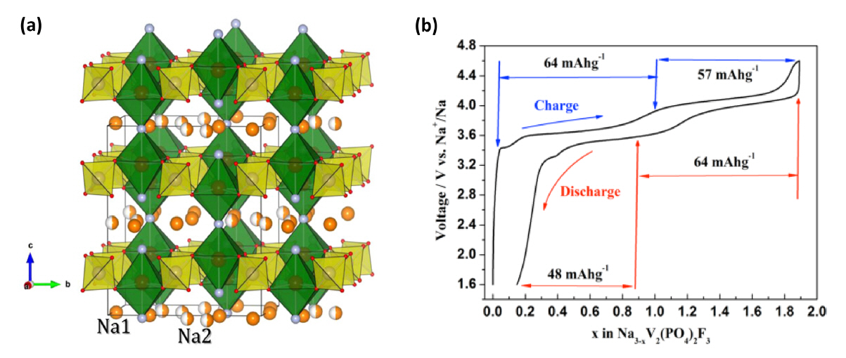
In 2014, Song et al. investigated the electrochemical behavior of Na3V2(PO4)2F3 [29]. The electrochemical voltage-composition curve of Na3V2(PO4)2F3 is shown in Fig. 1b. Two voltage plateaus at 3.7 and 4.1 V can be inferred for the charging process, during which 1.9 Na+ could be extracted from the crystal structure to forming the Na1.1V2(PO4)2F3. During the discharging process, only 1.8 Na+ are inserted back into the structure, resulting in the formation of Na2.9V2(PO4)2F3. This difference in Na+ insertion and extraction is associated with an irreversible electrochemical reaction and some side reaction occurs at the electrode/electrolyte interfaces that result in capacity losses [29].
The electrochemical insertion/extraction process is mainly attributed to the V3+/V4+ reaction (eq. 1), which is not related to V4+/V5+ because the plateau region at different voltage corresponds to the insertion/extraction of Na ions at different crystallographic sites [28,29]. In the voltage-composition curve, plateau at 3.4 V is corresponded to the extraction of Na+ ions from the Na3V2(PO4)3 and the latter plateaus are attributed to the extraction Na+ ions from the Na3V2(PO4)2F3 [32,33]. It is assumed that the NVPF prepared by Shakoor et al. was the mixed phase of Na3V2(PO4)2F3 and Na3V2(PO4)3. Furthermore, the reported XRD profile contained small diffraction peaks at 20, 23 and 32° are well matched with the Na3V2(PO4)3 XRD peaks [34]. Here, the first plateau region originated from the extraction of Na+ from the Na(2) site, because the Na(2) site is less stable than the Na(1) site, and therefore, the Na ions are not very the stable position due to the electrostatic repulsion of Na-Na that facilitate the extraction of the Na ion from the Na(2) site during the initial stage of charging. The calculated structural energy values for Na+ extraction from the Na(1) and Na(2) sites are - 1006.00 and -1009.05 kJ mol−1 respectively [28]. After complete extraction of the Na+ ion from the Na(2) site, the unstable of Na2V2(PO4)F3 structure is formed as a result of shorter Na-Na distance (2.92 Å). After reorganization the second Na-ion is extracted from the Na(1) sites at a higher potential (~4.1 V), which results in the formation of NaV2(PO4)2F3 at the end of the charging process [26,28,29]. After charging/discharging process, there is no change in the crystal structure of NVPF, which be explained by Shakoor et al. through their ex-situ XRD results [28]. The NVPF cathode material delivered an initial capacity of 92 mAh g−1 at 0.91 C current rate [29]. In addition, they also estimate the diffusion coefficient of Na ions by using CV analysis based on the relationship between peak current (ip) and the square root of scan rate (v1/2). The calculated diffusion coefficient was 2.04 × 10⁻¹¹ cm2 s−1 [29]. Generally, the NVPF electrode shows poor electronic conductivity owing to the insulating nature of PO4 3−, therefore, it is very difficult to attain high rate capability [35].
High rate capability is one of the important factors for practical application and is mainly associated with two factors: ionic diffusion and electronic conduction. Recent studies have suggested ideas on how to overcome this issue: (i) reducing the particle size to the nano level could effectively enhance ionic diffusion [36,37], and (ii) NVPF nanoparticles composite with carbonaceous material such as amorphous carbon and graphene can enhance the electronic conductivity. In addition, metal doping onto the vanadium site can considerably increase the intrinsic electronic conductivity of the material [26,35,38–40]. Recently, Chen’s group implemented a new synthesis strategy for boosting up the high power capability of the Na3V2(PO4)2F3 cathode [39]. They prepared the core/double shell structured Na3V2(PO4)2F3@CD nanocomposite through in situ coating of the carbon and the prepared particles were uniformly distributed in the mesoporous carbon framework. The schematic representation describeing the detailed synthesis strategy is shown in Fig. 2(a) [39]. Fig. 2b shows the HRTEM image, in which NVPF@C nanoparticles are incorporated into a mesoporous carbon structure and the thickness of the carbon coating is observed to be around 2 nm. The Na3V2(PO4)2F3@CD nanocomposite shows smaller redox polarization than NVPF/C composite based on CV analysis (not shown here), which suggests that fast electronic and ionic transport is achieved through the well dispersed mesoporous carbon conducting network [39]. Furthermore, charge discharge analysis demonst rated that the Na3V2(PO4)2F3@CD composite delivered 125, 123, 121, 116, 100, 92, 84 and 63 mAh g−1 at the current rate of 0.5, 1, 5, 10, 20, 30, 50 and 100 C respectively (Fig. 2c). The cycling stability was extended to 5000 cycles at 50 C rate, with a reversible capacity of 62 mAh g−1 and a capacity retention of 65% (Fig. 2d). These result revealed that the high electrochemical performances arise from the uniform distribution of the NVPF@C nanoparticles on the mesoporous carbon that offers sufficient electrochemical interfaces and abundant electronic/ionic pathways [39]. Following this, many studies have attempted to enhance the rate capability of Na3V2(PO4)2F3 by changing the conducting matrix to graphene, carbon nanofibers and carbon nanotubes [30,41–43]. All the composition remarkably enhanced the rate capability, Zhao et al. prepared an in situ carbon nanofibers coating on Na3V2 (PO4)2F3@C particles through chemical vapour deposition(CVD) (Fig. 3a) by using Fe as the catalyst at different ratios of NVPF@C to Fe (1:100, 5:100 and 10:100) [42]. CVD is a convenient method for producing highly conducting carbon with different structures [44,45]. Here, the NVPF@C@CNF-5 (5:100) sample was considered as the optimum one; upon increasing the Fe content, more or thicker carbon layers are formed on the surface of the active material. The thick carbon layer act as a barrier for Na-ion diffusion and thus affects the electrochemical performance even at low current density. The TEM image (Fig. 3b) of the NVPF@C@CNF-5 obviously shows that the NVPF@C particles are completely wrapped by the CNFs to form a three-dimensional electronic transfer network and the measured thickness of the carbon coating is around 2–3 nm (Fig. 3c). The electrochemical performance of NVPF@C@CNF-5 was analyzed at the high current rate of 20 C over 5000 cycles, a reversible capacity 93.3 mAh g−1 with a capacity retention of 86.3% at more than 99.5% coulombic efficiency were observed (Fig. 3d). The high rate capability and cyclability originated from the uniform wrapping of the CNFs on the NVPF@C particles. Here, the CNFs serve the dual role of a three-dimensional conducting framework and a buffering matrix. The first, role helps achieving a high rate charge/discharge ability, while the second role restricts the volume changes that occur during the insertion/extraction process [42].


In general, the electrochemical performance not only is related to the surface electronic conductivity but also depends on the intrinsic or bulk electronic conductivity of the electrode material [35]. The intrinsic electronic conductivity could be enhanced by ion doping onto the Na or vanadium sites in the NVP and NVPF structure [26,35,46–48]. Zhang et al. prepared Ti-doped Na3V2-xTix(PO4)2F3 and investigated it by experimental and DFT analysis [35]. The pristine NVPF shows a bandgap of 1.167 eV and it decreased to 1.049 eV with the doping of titanium ions onto the vanadium sites suggests that electronic conduction is easier in Ti-doped NVPF compared to pristine NVPF. The electrochemical results also confirmed that enhancements in cycling stability (91 mAh g−1 at 40 C over 500 cycles) and rate capability (81 mAh g−1 at 80 C) relative to the pristine material [35].
Barker et al. initially investigated NaVPO4F for application in Na-ion batteries. They refined the crystal structure the tetrahedral symmetry of Na3Al2(PO4)3F2 (space group I4/mmm) and explained the electrochemical reaction that occurred in a similar fashion to that involving Al compounds. Here, the extended three-dimensional network of [AlO4F2] octahedra and [PO4] tetrahedra that formation creates cavities, in which the Na ions are distributed. The full cell was fabricated using hard carbon and delivered an initial capacity of 79 mAh g−1 with an output voltage of 3.7 V [49]. Many groups investigated the electrochemical performance of NVPO4F by using different synthesis processes which are listed in Table 1 [50–53]. However, the electrochemical performance was not appropriately enhanced compared to the Na3V2(PO4)2F3 cathode material.

Electrochemical properties of sodium vanadium fluorophosphates.
2.2 Crystal structure, synthesis and electrochemical performance of Na3V2O2x(PO4)2F3-2x
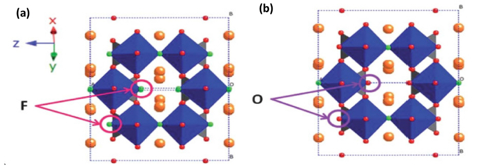
During the synthesis of Na3V2(PO4)2F3, a small amount of oxygen is incorporated into its crystal structure, which is typically denoted as Na3V2O2x(PO4)2F3-2x (x= 0 to 2); this amount mainly depends on the atmospheric condition and the carbon content during the synthesis process [54–64]. Fig. 4(a, b) indicates the structural correlation between Na3V2(PO4)2F3 (x=0) and Na3V2O2(PO4)2F (x=2). The structural and electrochemical performances of Na3V2O2x(PO4)2F3-2x have been analyzed by different groups [56–59]. These two structure shows a similar framework, because only the F atom is replaced by the O atom, which results in the vanadium existing in +3 and +4 oxidation states in Na3V2O2(PO4)2F, and in a mixed valence state on intermediate compounds (0<x<2). This structure mainly arises from the [VO5F] octahedrons and [PO4] tetrahedrons that form a layer by sharing one oxygen atom. Here, Na(1) and Na(2) are occupied by disordered Na+ in a circular geometry in the ab plane and the adjacent layer is connected through the F ions that are coordinated to two [VO5F] octahedrons; this structural arrangement presents a broad channel for the migration of Na+. In addition, Na+ exist in two types of coordination environment; the Na ion in the Na(1) site is coordinated by six O one F ions, whereas that in the Na(2) site is coordinated to six O ions [58,59].
A detailed investigation of the insertion/extraction reaction of Na3V2O2x(PO4)2F3-2x was carried out by Serras [56], through electrochemical measurements, ex-situ XRD and XAS analysis. In this compound, the vanadium exists as V3.77+, which was deduced by bond valence sum analysis (BVS) and substantiated by Vegard’s law. After the analysis, they proposed Na3V2O1.6(PO4)2F1.4 as the final composition. The electrochemical reaction involving the proposed compound was examined under different charge/discharging states and is shown in Fig. 5a. The electrochemical reaction is either single or multiphase, and was analyzed by ex-situ XRD analysis. It was confirmed that a single phase reaction occurred because the diffraction peaks and lattice parameter were unchanged during the charging/discharging process owing to the expansion and contraction of lattice (Fig. 5b). After the extraction of Na+, the Na-ion tunnels became smaller in the x and y-direction and wider in the z-direction (Fig. 5c) which agreed well with the lattice parameter values. In addition, the valence state was analyzed through XANES analysis, in which the pre-edge zone was assigned to V3+ (5468 eV), V4+ (5469.5 eV) and V5+ (5471 eV), which are indicated by arrows (Fig. 5d). The intensity of the lowest energy V3+ peak remained constant throughout the charging process, which corroborated that V3+ was not involved in the oxidation process. On the other hand, the intensity of the V4+ peak decreased, while that of V5+ increased subsequently during the charging process to suggest that V4+ oxidized to V5+. Further, they calculated the percentage of vanadium state by linear fitting analysis to obtain values of ~82% for V4+ and 18% for V3+. Based on the oxidation of vanadium, they proposed the following reaction mechanism:

(a) Electrochemical voltage-composition curve and post-mortem points, (b) Lattice parameter evolution of Na3V2O2x(PO4)2F3-2x, (c) evolution of F(1)-F(1) and F(2)-F(2) distances during charging, and (d) Vanadium K-edge preedge feature of the samples and the standards. Reprinted with permission from Ref. [56]. Copyright © 2013 American Chemical Society.
Dai’s group recently synthesized Na3V2O2(PO4)2F nanoparticles at low temperature and their synthesis process is shown in Fig. 6a [57]. The charge-discharge profile of the Na3V2O2(PO4)2F nanoparticles, shown in Fig. 6b, reveals two redox potentials at 3.65/3.60 V and 4.07/4.00 V that corresponds to the extraction/insertion of Na+ into the Na(1) and Na(2) sites of the crystal structure. The Na3V2O2(PO4)2F nanoparticles delivered a high reversible capacity of 112 mAh g−1 at 0.5 C rate and retained 90% of the capacity over 1200 cycles at 2 C rate (Fig. 6c). The excellent cyclability and high rate performance are attributed to the nanosized particles that effectively shorten the electronic/ionic diffusion pathways and buffer the volume change occurring during the cycling process. Finally, we have summarized the electrochemical performance of previously reported NVPF in Table 1.

(a) Synthesis process of Na3V2O2(PO4)2F nanoparticles, (b) charge-discharge profile in the potential window 2.5-4.5 V at C/5 rate, and (c) cycling stability curve of Na3V2O2(PO4)2F nanoparticles at 2 C rate. Reprinted with permission from Ref. [57]. Copyright © 2015 Wiley-VCH Verlag GmbH&Co. KGaA.
2.3 Crystal structure and electrochemical performance of Na3V2O2x(PO4)2F3-2x
In 2013, Kang’s group introduced the cathode material Na1.5VPO4F0.7 for high-energy Na-ion batteries [62]. Na1.5VPO4F0.7 belongs to the P42/mnm space group and is isostructural with Na1.5VPO5 and Na3V2(PO4)2F3 [63]. The structure of Na1.5VPO4F0.7 consists of corner sharing between the PO4 tetrahedral and VO5F/VO4F2 octahedral units that form a three-dimensional open framework, with the Na ions forming the Na layers on the ab plane of the structure (Fig. 7a). Noticeably, vanadium has two types of local environments, namely VO5F and VO4F2 octahedra, in the presence of F−. The researchers examined the vanadium state and structural stability during the chargingdischarging process through XANES and ex-situ XRD, respectively. In XANES analysis (Fig. 7c), the edge of the spectrum shifted towards higher energy and completely reverted to the original state, which implied that the oxidation of vanadium is reversible during the charging/discharging process. The ex-situ XRD pattern shows that during the charging process (corresponding to the extraction of 0.5 Na+), the peak is continuously shifted and peak splitting is observed in a 30% state of charging (SOC), which indicates the coexistence of two phases. For 50% SOC, the final phase Na0.5VPO4.8F0.7 is formed, which could be reversed during the discharging process (Fig. 7d). Moreover, a high average voltage of 3.8 V with 83% capacity retention over 500 cycles at 1 C current rate is observed. According to its theoretical capacity (155.6 mAh g−1 for 1.2 Na+ extraction), the energy density is nearly 600 Wh kg−1. These findings concluded that the Na1.5VPO4.8F0.7 cathode is one of the highest energy density cathode materials reported so far (Fig. 7e) [62].
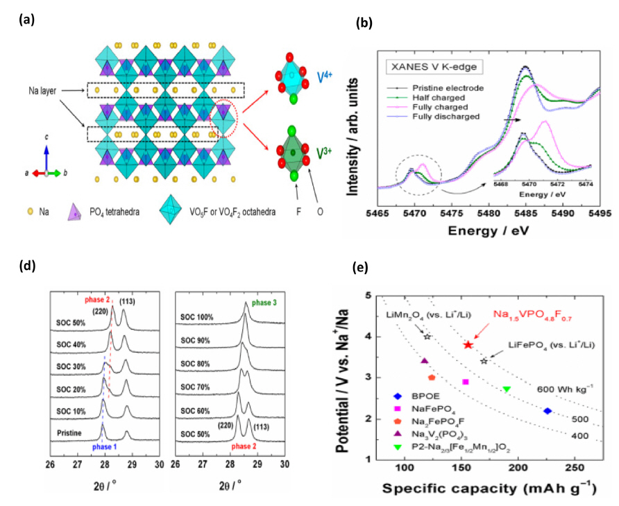
(a) Crystal structure of Na1.5VPO4.8F0.7 and the local environment of the vanadium ions, (b, c) XANES and ex-situ XRD patterns of the charging-discharging process, and (d) comparison of the energy density with those of different cathode materials. Reprinted with permission from Ref. [62]. Copyright © 2013 American Chemical Society.
3. Conclusion and outlook
In this review, we have elucidated the potential advantage of NVPF cathode material, its crystal structure and the charge storage mechanism. Here, the Na3V2(PO4)2F3 exhibits the high voltage redox couple owing to strong inductive effect of F. Na3V2O2(PO4)2F structure is isostructural system of Na3V2(PO4)2F3 by substitution of O ion to F ion and i t makes di fferent intermedi a te products (Na3V2Ox(PO4)2F1+2x (0 ≤ x ≥ 1). Compared with Na3V2(PO4)2F3, Na3V2O2(PO4)2F has slightly lower the redox potential. However, specific amount of oxygen substitution decreases the Na+-Na+ repulsion that allows the extra Na+ extraction below 4.5 V, therefore, leads to achieve a high energy density Naion battery [55]. In addition, the Na3V2O2(PO4)2F offers the additional capacity of 65 mAh g−1 when potential window is 1–4.3 V, which occur the high energy density of 600 Wh kg−1 [32]. Therefore, it offers the chance to analyzing the electrochemical performance of Na3V2Ox(PO4)2F1+2x (0 ≤ x ≥ 1) system at different potential window for the extraction of third Na+. From a practical application point of view, we have briefly discussed how to improve the cycling stability and rate capability based on particle size, the fabrication of graphene composite, and doping with metal ions. All the strategies could be effective in enhancing the electrochemical performance of Na3V2(PO4)2F3. On the other hand, some reports reveal that water based binder (CMC and Na-alginate) also favor for the enhancement of the cycling stability by accommodating the volume expansion occurring during the sodiation/de-sodiation process. Na3V2(PO4)2F3 coupled with a suitable high capacity and low potential anode material such as Tin (Sn), Phosphorous (P) and Iron and Germanium Phosphide (FeP and GeP) can help the high energy density of the Na-ion batteries. Recent research has obviously demonstrated the outstanding electrochemical performance of the NVPF electrode material in terms of good cycling stability, high rate capability and high potential. It is concluded that the NVPF electrode material can be considered as the best candidate for high energy Na-ion storage devices. Further, the NVPF electrode material will lay down a new pathway for Na-ion hybrid capacitor and Na-ion aqueous batteries.