Enhanced Cathode/Sulfide Electrolyte Interface Stability Using an Li2ZrO3 Coating for All-Solid-State Batteries
Article information
Abstract
In this study, a Li2ZrO3 coated Li[Ni0.8Co0.15Al0.05]O2 (NCA) cathode was applied to an all-solid-state cell employing a sulfide-based solid electrolyte. Sulfide-based solid electrolytes are preferable for all-solid-state cells because of their high ionic conductivity and good softness and elasticity. However, sulfides are very reactive with oxide cathodes, and this reduces the stability of the cathode/electrolyte interface of all-solid-state cells. Li2ZrO3 is expected to be a suitable coating material for the cathode because it can suppress the undesirable reactions at the cathode/sulfide electrolyte interface because of its good stability and high ionic conductivity. Cells employing Li2ZrO3 coated NCA showed superior capacity to those employing pristine NCA. Analysis by X-ray photoelectron spectroscopy and electron energy loss spectroscopy confirmed that the Li2ZrO3 coating layer suppresses the propagation of S and P into the cathode and the reaction between the cathode and the sulfide solid electrolyte. These results show that Li2ZrO3 coating is promising for reducing undesirable side reactions at the cathode/electrolyte interface of all-solid-state-cells.
1. Introduction
Lithium-ion batteries (LIBs) have played an important role in energy storage for portable devices and transport applications [1-6]. However, there are safety concerns concerning conventional LIBs because of the use of flammable organic liquid electrolytes; this problem is aggravated when LIBs are used for large-scale energy storage systems. All-solid-state lithium batteries (ASSBs) using nonflammable solid electrolytes are considered a promising alternative to conventional LIBs because they solve the safety issue of LIBs associated with liquid electrolytes [7-8]. Recently the development of ASSBs employing solid electrolytes has accelerated rapidly [7-13]. The properties of ASSBs are highly dependent upon the solid electrolyte, and a high ionic conductivity is required. Sodium super ionic conductor (NASICON)-type [14,15] and garnet-types oxides [16] are expected to be feasible solid electrolytes for ASSBs because of their good ionic conductivity (around 10-3 S·cm-1). However, they require sintering at high temperatures in order to obtain sufficient contact between the cathode and the solid electrolyte, which inevitably results in high interfacial resistance attributed to unwanted side reactions. Sulfide-based solid electrolytes are also preferable for ASSBs because they not only have high ionic conductivity but also good softness and elasticity, which makes it possible to form good interfacial connections between the cathode and solid electrolyte through simple mechanical pressing at room temperature [17-22]. Despite these advantages, sulfides suffer from interfacial instability with oxide cathodes. The reaction at the cathode/sulfide electrolyte interface forms an undesirable interfacial layer, disturbing the movement of Li ions and electrons [17]. Moreover, a space-charge layer (SCL) is also formed at the interface on the sulfide side, decreasing the conductivity of the interfacial region [18]. Interfacial instability is the main scientific issue limiting the commercialization of ASSBs based on solid sulfide electrolytes. For this reason, considerable effort has been made to enhance the interfacial stability between the oxide cathode and the sulfide electrolyte [23-26].
The surface modification of cathodes by coating with stable oxides has been suggested to suppress interfacial instability. Several oxides such as LiNbO3 [27], Li4Ti5O12 [28], and Li2O-SiO2 [29] have been used to decrease interfacial resistance for LiCoO2, a commercially used cathode material. Actually, the surface coating process has been widely applied to cathodes for LIBs, to reduce unwanted reactions between the cathode and reactive organic liquid-electrolyte [30-36]. In comparison, surface coating for ASSBs using an inorganic solid electrolyte (such as a sulfide) is still at an early stage, so most investigations have used LiCoO2 as the cathode material. Based on previous reports [27-36], the effects of the surface coating on the cathode depend significantly on the coating material, cathode properties, and coating thickness and shape. Hence, the control of these factors is a key point for the successful introduction of ASSB surface coatings.
In this study, Li2ZrO3 was applied as a coating material on the surface of a Li[Ni0.8Co0.15Al0.05]O2 (NCA) cathode for ASSBs using solid sulfide electrolytes. Li2ZrO3 has a high ionic conductivity, as well as good stability [37-38], allowing it to suppress unwanted reactions at the cathode/sulfide electrolyte interface, and to facilitate the movement of lithium ions during the charge-discharge process. A Li2O-ZrO2 coating has already been applied to the cathode of ASSB cells and it showed enhanced electrochemical performance [38]. In our work, the suppression of undesirable interfacial reactions by Li2ZrO3 coating is the particular focus. The coating effect at the interface was carefully characterized using X-ray photoelectron spectroscopy (XPS), transmission electron microscopy (TEM), and electron energy loss spectroscopy (EELS), as well as by evaluating the electrochemical performance of the ASSB cells.
2. Experimental
The cathode material used in this work was Li[Ni0.8Co0.15Al0.05]O2 (NCA) powder prepared by a coprecipitation method. The surface of pristine NCA powder was modified using Li2ZrO3. The experimental method followed that of a previous study [39]. The Li2ZrO3-coating solution was prepared using lithium nitrate (LiNO3, Aldrich), zirconium(IV) oxynitrate hydrate (N2O7Zr·xH2O, Aldrich) and ethanol (99.9%, Aldrich). The pristine powder was mixed with Li2ZrO3 coating solution and stirred at 70℃ until all the solvent evaporated. Then the sample was dried at 90℃ for 1 day and annealed at 800℃ for 1 h in air. The Li2ZrO3 content was adjusted to 1.0 and 3.0 wt.% of the cathode powder. The surface morphology of the samples was analyzed using field-emission scanning electron microscopy (FE-SEM, Nova Nano 200).
For electrochemical testing, all-solid-state cells were fabricated using sulfide-based electrolyte (70% Li2S-30% P2S5). The cathode mixtures for the composite electrodes were prepared by hand-mixing the cathode material (pristine or Li2ZrO3-coated NCA), the sulfide-based solid electrolyte, and carbon black (super P) in a weight ratio of 70:30:2. The mixtures were compressed at 30 MPa, followed by grinding; this sequence was repeated three times to produce uniform composites. To form the solid electrolyte layer, 0.2 g of the sulfide-based electrolyte was compressed at 30 MPa using a 16-mm-diameter mold. Thereafter, the composite cathode layer was formed on one side of the solid electrolyte using the cathode mixture and carbon nanotube (CNT) paper. The anode electrode layer was formed on the opposite side with 0.05 g of lithium-indium powder and nickel foil. The cathode/electrolyte/anode assemblies were placed inside 2032 coin-type cells and subjected to galvanostatic cycling (WonATech voltammetry system) in the 3.68-1.88 V potential window at various charge-discharge rates.
The interface between the cathode and sulfide-based electrolyte was observed using TEM (Titan 80-300), energy dispersive spectrometry (EDS, installed in the TEM), and EELS (installed in the TEM). XPS (Thermo Scientific K-Alpha) was also used to analyze the surface reactions of the composite electrodes. The composite electrodes before and after cycling were separated from the cells and stored in a dry box. The electrodes were packed in a vacuum during transfer to the instruments, and the top 50 nm were etched using Ar sputtering to remove surface contaminants before analysis. To observe the interface between the cathode and solid electrolyte precisely, the cross-sectional interface of the composite electrode was prepared using focused ion beam milling (FIB).
3. Results and Discussion
Fig. 1 shows SEM images of the pristine and Li2ZrO3-coated (1.0 and 3.0 wt.%) NCA powder. As shown in Fig. 1(a), the surface of the pristine powder seems to be already covered with a film layer. This film may be an impurity layer composed of Li2CO3 or LiOH formed on the surface because the NCA cathode contains a large amount of Ni that is easily decomposed during storage [40]. Because of the already formed film layer, the Li2ZrO3 coating layer was not clearly observed on the surface of the coated NCA powder (Figs. 1(b) and 1(c)). However, small particles, expected to be Li2ZrO3, are distributed on the surface of the powder. The size of the particles increased as the amount of Li2ZrO3 coating increased. Fig. 2 presents EDS mapping (Zr and Ni) of the Li2ZrO3 coated samples. Both Ni and Zr seem to be homogeneously distributed on the surface of the powders.

SEM images of Li[Ni0.8Co0.15Al0.05]O2 (NCA) powder. (a) Pristine powder, (b) 1.0 wt.% Li2ZrO3 coated powder, and (c) 3.0 wt.% Li2ZrO3 coated powder.

SEM images and EDS mapping (Zr and Ni) of Li[Ni0.8Co0.15Al0.05]O2 (NCA) powder. (a) 1.0 wt.% Li2ZrO3 coated powder, and (b) 3.0 wt.% Li2ZrO3 coated powder.
The pristine and Li2ZrO3 coated NCA cathodes were mixed with the sulfide-based solid electrolyte and carbon black to prepare composite electrodes. Prior to measurement of the electrochemical performance, the interface between the Li2ZrO3-coated cathode and the sulfide-based solid electrolyte was observed using TEM and EDS to verify the presence of the Li2ZrO3 coating. The left side of Fig. 3 shows a TEM image of the cathode/solid electrolyte interface of the composite electrode. The cathode is 1 wt.% Li2ZrO3 coated NCA. There are small particles visible as a coating layer between the cathode and electrolyte. To identify the coating material, we assigned five areas (marked with a red square on the left side of Fig. 3) of the TEM images for EDS analysis. As shown in the right side of Fig. 3, the small particles in the interface (areas 1, 3, and 4) yield Zr peaks, which indicates that the Li2ZrO3 coating layer had successfully formed at the interface between the NCA cathode and the sulfide-based solid electrolyte. The EDS peaks of area 2 show that the cathode is composed of Ni, Co, and O. And area 5 is composed of S and P, which are the major elements in the sulfide-based solid electrolyte.
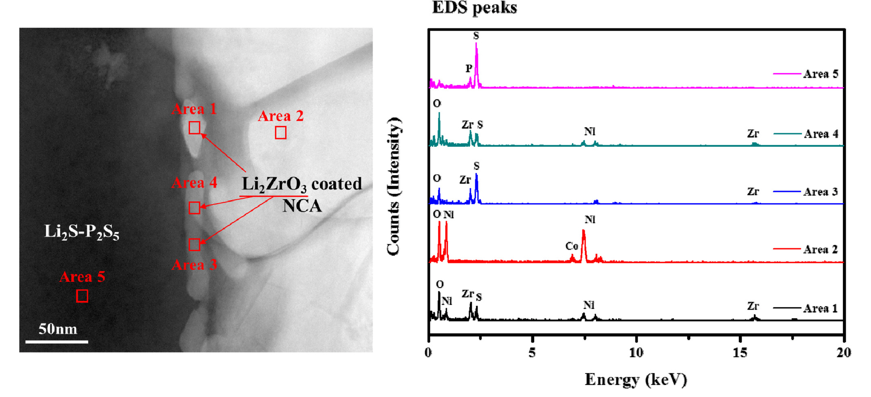
TEM image (left side) and EDS peaks (right side) of the interface between 1.0 wt.% Li2ZrO3-coated NCA cathode and sulfide-based solid electrolyte. Five areas in the TEM images (marked with a red square) were assigned for EDS analysis.
The electrochemical performance of the composite electrodes employing pristine and Li2ZrO3 coated NCA cathodes was measured using all-solid-state cells to determine the effect of the coating layer. Fig. 4(a) shows the discharge capacities of the composite electrodes at various current densities (8.5, 17, 34, 85, and 170 mA·g-1) over the voltage range 3.68-1.88 V. At low current density (8.5 mA·g-1), the initial capacities of the all-solid-state cells were ca. 190-220 mAh·g-1, which are values similar to those of cells using liquid electrolytes. However, as the current density increases, the capacities of the all-solid-state cells decrease significantly. At a current density of 34 mA·g-1 (approximately 0.2 C rate), the composite electrodes of the all-solid-state cells have capacities of only 90 to 110 mAh·g-1. This implies that the internal resistance of the all-solid-state cells is much higher than that of conventional cells using liquid electrolyte. However, the cells employing Li2ZrO3 coated electrodes demonstrate higher capacity than the cell with a pristine electrode. Generally, side reactions between the cathode and sulfide-based solid electrolyte form an undesirable interface layer that increases the interface resistance of all-solid-state cells, resulting in reduced capacity and inferior rate capability compared to lithium-ion cells using a liquid electrolyte. Thus, the improved capacity of the all-solid-state cells employing Li2ZrO3 coated electrode is attributed to reduced side reactions at the cathode/solid electrolyte interface because of the Li2ZrO3 coating effect.

(a) Discharge capacities of the pristine, 1.0 wt.%, and 3.0 wt.% Li2ZrO3 coated NCA electrodes at current densities of 8.5, 17, 34, 85, and 170 mA·g-1 over the voltage range 3.68-1.88 V. Charge-discharge profiles of the pristine and Li2ZrO3-coated NCA electrodes at (b) 8.5, (c) 17, and (d) 85 mA·g-1.
Figs. 4(b)-4(d) show the voltage profiles of the all-solid-state cells employing pristine and Li2ZrO3-coated NCA electrodes, measured at 8.5, 17, and 85 mA·g-1, respectively. These correspond to the 1st, 6th, and 16th cycles shown in Fig. 4a. The 3 wt.% Li2ZrO3-coated sample shows the highest capacity among the three samples at 8.5 mA·g-1 (Fig. 4(b)). However, at a high current density (85 mA·g-1), the 1 wt.% Li2ZrO3-coated NCA shows better capacity than that of the 3 wt.% coated sample (Figs. 4(c) and 4(d)), indicating that, of the all-solid-state cells, the 1 wt.% Li2ZrO3 coating has better rate capability than the 3 wt.% Li2ZrO3 coating.
The cyclic performance of the composite electrodes employing pristine and Li2ZrO3-coated NCA electrodes was observed at a current density of 17 mA·g-1, as shown in Fig. 5. The cyclic performance of the composite electrodes of all-solid-state cells is relatively stable. However, the capacity of all electrodes slowly decreases with increasing cycle number. This capacity loss during cycling may be associated with side reactions at the cathode/electrolyte interface, unstable mechanical contact between the electrodes and solid electrolyte, or degradation of the sulfide-based electrolyte and electrodes. However, it is difficult to accurately analyze the cause of the capacity loss during cycling under the conditions used.
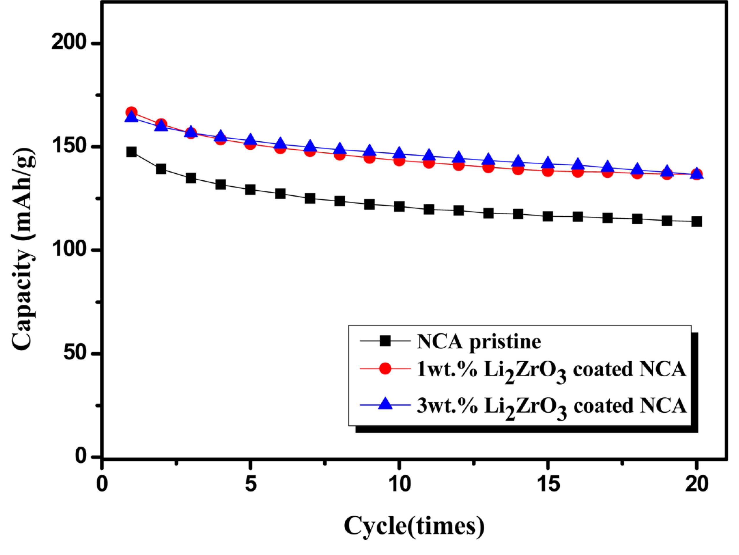
Cyclic performance of the pristine, 1.0 wt.%, and 3.0 wt.% Li2ZrO3-coated NCA electrodes at a current density of 17 mA·g-1.
To identify the coating effect more clearly, XPS and EELS analyses were used for observation of the all-solid-state cells. Fig. 6 presents XPS spectra of the pristine sulfide-based solid electrolyte and the composite electrode employing pristine and 1 wt.% Li2ZrO3-coated NCA. As shown in Fig. 6a, the S 2p spectrum of the pristine sulfide-based solid electrolyte shows two main peaks attributed to the S 2p1/2 and 2p3/2 components (marked in blue). The peaks marked with red are associated with oxidation of the sulfur. Figs. 6(b) and 6(c) show the S 2p spectrum of the composite electrodes after 30 cycles. The peaks related to S 2p1/2 and 2p3/2 components (blue) are significantly reduced, and new peaks associated with side reactions (marked in orange and red) appear. This means that side reactions between the cathode and the sulfide-based electrolyte actively progressed during cycling. However, the S 2p spectrum of the composite electrode employing Li2ZrO3-coated NCA showed relatively higher blue peaks and lower red and orange peaks, indicating that the coating layer at the cathode/electrolyte interface somewhat reduced the side reactions. As shown in Fig. 6(d), the P 2p spectrum of the pristine sulfide-based solid electrolyte consists of two main peaks attributed to the P 2p1/2 and 2p3/2 components (blue peaks) and some small side peaks related to the oxidized phosphorous (orange and red peaks). The P 2p spectra of the composite electrodes also changed after cycling compared with that of the pristine sulfide-based electrolyte. The main peaks (blue peaks) are reduced, and the red and orange peaks attributed to the side reactions increase (Figs. 6(e) and 6(f)). However, the composite electrode employing Li2ZrO3-coated NCA contains relatively intense main peaks and small red and orange peaks compared to the composite electrode employing pristine NCA, indicating that the side reactions were suppressed by the Li2ZrO3 coating.
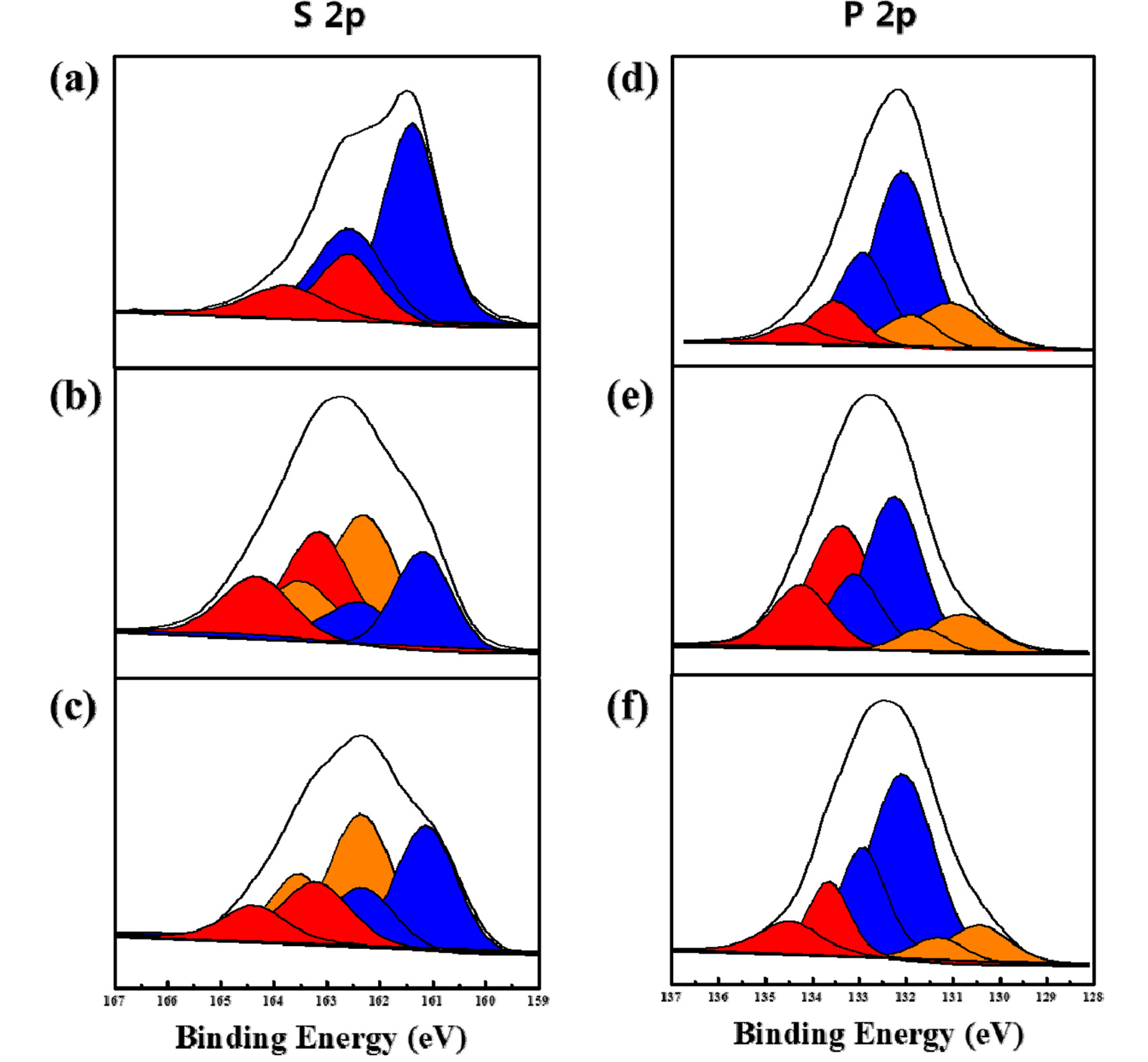
S 2p XPS spectra of the (a) pristine solid electrolyte, and composite electrode after 30 cycles employing (b) pristine NCA and (c) 1.0 wt.% Li2ZrO3-coated NCA. P 2p XPS spectra of the (d) pristine solid electrolyte, and composite electrode after 30 cycles employing (e) pristine NCA and (f) 1.0 wt.% Li2ZrO3-coated NCA.
Fig. 7 shows the TEM images and EELS analyses of the cathode/electrolyte interface of the composite electrode after 30 cycles. The cross-sectional interface was prepared using focused ion bean milling from the cycled cells. In addition, EELS analysis was performed through a cross-section from the sulfide-based solid electrolyte to the NCA cathode. As shown in Fig. 7(a), the cathode part of the composite electrode employing pristine NCA contains a considerable amount of S and P, which is associated with the side reaction between the cathode and the sulfide-based electrolyte. However, at the interface having a Li2ZrO3 coating layer, the result is quite different. As shown in the TEM image in Fig. 7(b), a Li2ZrO3 layer exists between the cathode and sulfide-based electrolyte in this composite electrode. Interestingly, the amount of S and P in the cathode part was dramatically reduced with respect to the Li2ZrO3 layer. This result clearly shows the Li2ZrO3 can effectively prevent the propagation of S and P into the cathode, which also means that the side reactions attributed to the reaction between cathode, and the propagated S and P, can be suppressed by the Li2ZrO3 coating layer. Therefore, the composite electrodes employing Li2ZrO3 coated NCA show reduced side reactions during cycling, as also confirmed by XPS analysis in Fig. 6, which results in a relatively high capacity compared to that of the composite electrode employing pristine NCA.
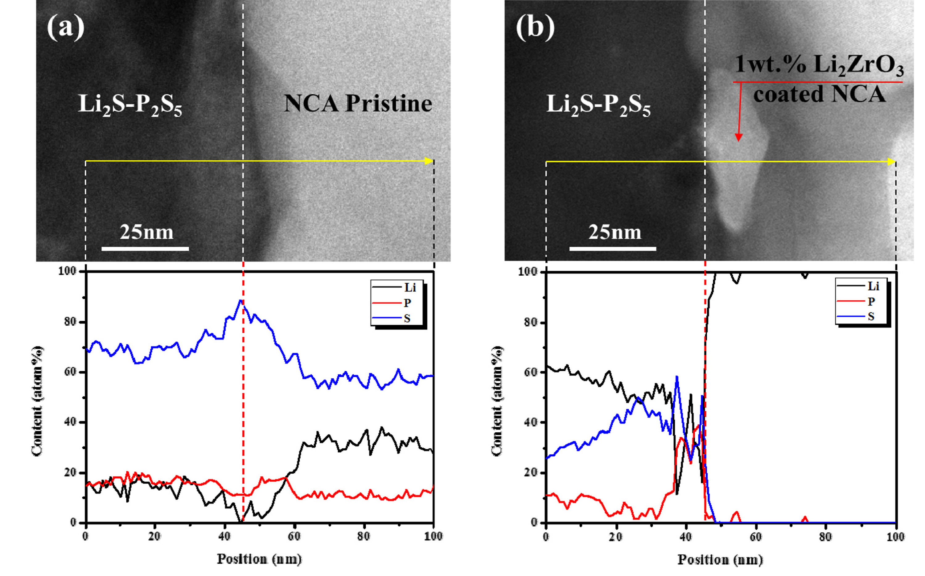
TEM and EELS analyses of the interface between sulfide-based solid electrolyte and cathode. (a) Pristine NCA as the cathode and (b) 1.0 wt.% Li2ZrO3-coated NCA as the cathode.
4. Conclusions
To suppress undesirable side reactions between the sulfide-based solid electrolyte and the NCA cathode, Li2ZrO3 was introduced as a coating material. The composite electrodes of the all-solid-state cells employing Li2ZrO3 coated NCA had higher capacities than that employing pristine NCA, although their capacities were somewhat lower than a conventional lithium-ion cell using a liquid electrolyte. XPS analysis showed that the S 2p and P 2p spectra of the composite electrodes were significantly changed compared to those of the pristine sulfide-based electrolyte, attributed to side reactions between the NCA cathode and electrolyte. However, the spectra of the composite electrode employing LLi2ZrO3-coated NCA showed much more intense main peaks related to S 2p and P 2p and smaller side peaks associated with side reactions compared with those of the composite electrode employing prist ine NCA. Moreover, it was confirmed by TEM and EELS analyses that the Li2ZrO3 coating layer successfully prevented the propagation of S and P into the cathode during cycling. This result indicates that Li2ZrO3 coating can suppress the side reactions at the NCA cathode/sulfide-based solid electrolyte interface, which results in an improved capacity of all-solid-state cells employing coated cathodes.
Acknowledgements
This work was supported by Kyonggi University Research Grant 2016.