Chitosan-Cu-salen/Carbon Nano-Composite Based Electrode for the Enzyme-less Electrochemical Sensing of Hydrogen Peroxide
Article information
Abstract
Cu-Salen complex was prepared and attached into chitosan (Cs) polymer backbone. Nanocomposite of the synthesized polymer was prepared with functionalized carbon nano-particles (Cs-Cu-sal/C) to modify the electrode surface. The surface morphology of (Cs-Cu-sal/C) nanocomposite film showed a homogeneous distribution of carbon nanoparticles within the polymeric matrix. The cyclic voltammogram of the modified electrode exhibited a redox behavior at −0.1 V vs. Ag/AgCl (3 M KCl) in 0.1M PB (pH 7) and showed an excellent hydrogen peroxide reduction activity. The Cs-Cu-sal/C electrode displays a linear response from 5×10⁻⁶ to 5×10⁻⁴ M, with a correlation coefficient of 0.993 and detection limit of 0.9 μM (at S/N = 3). The sensitivity of the electrode was found to be 0.356 μA μM-1 cm-2.
1. Introduction
Electrode modifications with redox-active moieties or a functional groups has gain a great interest, due to their fundamental importance in electrochemical catalysis and bio-sensing where transition metal complexes are used as an electro-catalyst due to their tunable redox potential [1-3]. Tetra dentate Schiff base ligands have been extensively used as catalysts in organic reactions and bio-mimetic enzymatic reactions [4,5]. Salen based electro-active complexes and their polymers have potential applications in the field of electro-catalysts, chemical sensors and optical devices [6,7]. The metal complexes are often coated on the electrode surfaces either by electro-deposition or immobilizing them with polymer matrix for the catalytic purposes[8-10]. Copper complexes of salen-type ligands are important in some biochemical processes, and DNA cleavage and antimicrobial activity [11-14]. Cu-salen complexes and metal organic frame work have been prepared and their properties had been studied well [15-17].
Chitosan is an amino-polysaccharide prepared by deacetylation of chitin, which is discarded as industrial waste so it can be considered as a low cost and nonhazardous polymer [18,19]. Chitosan bears free amine groups which are used for the immobilization of the metal complexes and redox mediators [20-23]. Currently, much attention has been focused on developing new nano-materials, which are used for signal amplification in electrochemical methods [24]. Conducting nanomaterials with a larger surface area are the potential candidates for biomolecules immobilization and signal amplifications [25]. Among the available materials used, carbon nano-materials are the most exciting because of their unique physical, chemical and mechanical properties [26,27].
Hydrogen peroxide is a vital compound in the biological transformations also widely used in several fields like food production and chemical industries, therefore, determination of hydrogen peroxide becomes an important task in the field of biosensor development [28]. Number of methods have been established for the detection of hydrogen peroxide [29,30]. The electrochemical sensors developed by immobilizations of enzymes and mediators are also employed for detection of hydrogen peroxide [31]. Electrodes modified with the transition metal hexaferrocynates and metal oxides were used for the direct electro-catalytic sensing of H2O2 [32,33]. Recently, the synthesis of a new bimetallic metalloporphyrinic framework of Cu(II) complex and its electrochemical application for the hydrogen peroxide detection has been reported [34].
The present work describes the synthesis of Cu-salen coordinated chitosan polymer (Cs-Cu-sal). Redox active nano-composite of Cs-Cu-sal was prepared by simple mixing with functionalized carbon nanoparticles. Cs-Cu-sal/C composite was drop coated on the printed carbon electrodes and these modified electrodes were tested for H2O2 sensing by cyclic voltammetric and i-t curve techniques. The Cs-Cu-sal/C electrode showed the sensitivity of 0.356 μA μM-1cm-2 with the linear range of 5×10⁻⁶ to 5×10⁻⁴ M for the hydrogen peroxide sensing.
2. Experimental
2.1 Reagents
Chitosan (lower mol. wt.), copper(II)acetate monohydrate, ethylene diamine, 2-hydroxy benzaldehyde, acetic acid and hydrogen peroxide were obtained from Sigma Aldrich and membrane filters from the Millipore. All the chemicals were of analytical grades and used without further purification. Water purified from Millipore system was used in all the experiments. 0.1 M phosphate buffer (pH 7.0) solution was prepared with Na2HPO4 and NaH2PO4.
2.2 Surface characterizations
The surface morphology of the composite film on a printed carbon electrode was recorded with the use of a field emission scanning electron microscope, Hitachi S-4300 at 15 KV.
2.3 Electrochemical experiments
Cyclic voltammetry was performed with printed carbon electrode (PCE, 5 mm, SE100, Zensar R & D, Taiwan) as working, Ag/AgCl (3 M KCl) as reference and platinum wire as counter electrodes. All the experiments were performed in 0.1 M phosphate buffer at pH 7 under argon atmosphere at the room temperature. CHI 900 potentiostat (CH Instruments, USA) was used for electrochemical measurements.
2.4 Synthesis of Cs-Cu-sal Polymer
2.4.1 Preparation of the salen ligand
Ethylenediamine (60 mg) and salicylaldehyde (244 mg) in 1:2 molar ratio were added in ethanol and the mixture was heated to reflux for 1 h. Bright yellow crystalline solid of salen [N,N-ethylenebis(salicylidene-aminato)] ligand was formed which was collected by filtration and washed thoroughly with ethanol.
2.4.2 Neat Cu-salen complex
Solution of Cu(CH3COOH) (181 mg) in 10 mL (methanol:water; 7:3 v/v) was added slowly to salen (272 mg) in 15 mL methanol under stirring at room temperature. The resulting mixture was heated to reflux at 80℃ for 1 h and the solid complex formed was isolated by filtration. The dark green crystals of Cu-salen complex thoroughly washed with methanol and dried, which is referred as Cu (II)-salen.
2.4.3 Cs-Cu-sal polymer
Neat Cu-salen solution in methanol was added dropwise to 1% chitosan in 1% aqueous acetic acid and stirred overnight. The resulting Cs-Cu-sal was filtered through 10,000 molecular weight cut-off polycarbonate membrane to remove the low molecular weight polymer. The obtained polymer was precipitated with acetone, collected and dried under the vacuum.
2.5 Treatment of carbon
Commercially available carbon black (C) powder was treated with acid as per earlier reported procedure [20]. The carbon black powder was boiled in 5 M HNO3 for a shorter time, filtered and repeatedly washed with deionized water. Functionalized carbon black was dried and used for the Cs-Cu-sal polymer nano-composite preparation.
2.6 Preparation of electrodes
200 μL of 1% Cs-Cu-sal polymer in 1% acetic acid (10 mg/mL) and 2 mg of acid treated carbon (C) powder were mixed and sonicated for 1 minute. 2 μL of this Cs-Cu-sal/C composite material was drop coated on the PCE. Air dried electrodes were washed with water and used for the further electrochemical and other characterization.
3. Results and Discussion
Cs-Cu-sal polymer was synthesized in two steps procedure as presented in Scheme 1. In the first step, Cu-salen complex was prepared by mixing salen ligand and Cu acetate in methanol : water solvent. The chitosan polymer was modified with Cu-Sal complex by simple mixing of 1% chitosan in 1% acetic acid solution with the metal complex. The composite of the Cu complex attached polymer with functionalized carbon nano powder was prepared by mixing them and sonication. The PCEs were modified by drop coating of Cs-Cu-sal/C and dried it at room temperature.

Synthesis of Cs-Cu-sal polymer.
Fig. 1(A) showed the SEM image of Cs-Cu-sal/C polymer composite film and Fig. 1(B) showed the image of the pristine carbon nanoparticles. The sizes of the pristine carbon particles and the carbon particles embedded in the polymer composite were observed in the range of 50 to 100 nm. The functionalized carbon particles having slightly negative charge and Cs-Cu-sal polymer having slightly positive charge in acidic pH due to the protonation of the free amines of the chitosan polymer. The polymer composite was prepared by sonication of functionalized carbon and polymer in the solution, the polymer with positive charge can form the thin film on the negatively charge high surface area carbon particles. The homogeneous distribution of the carbon particles in the polymer produces a three dimensional homogeneous porous film and the presence of polymer was in the composite was supported by the electrochemical characterizations.
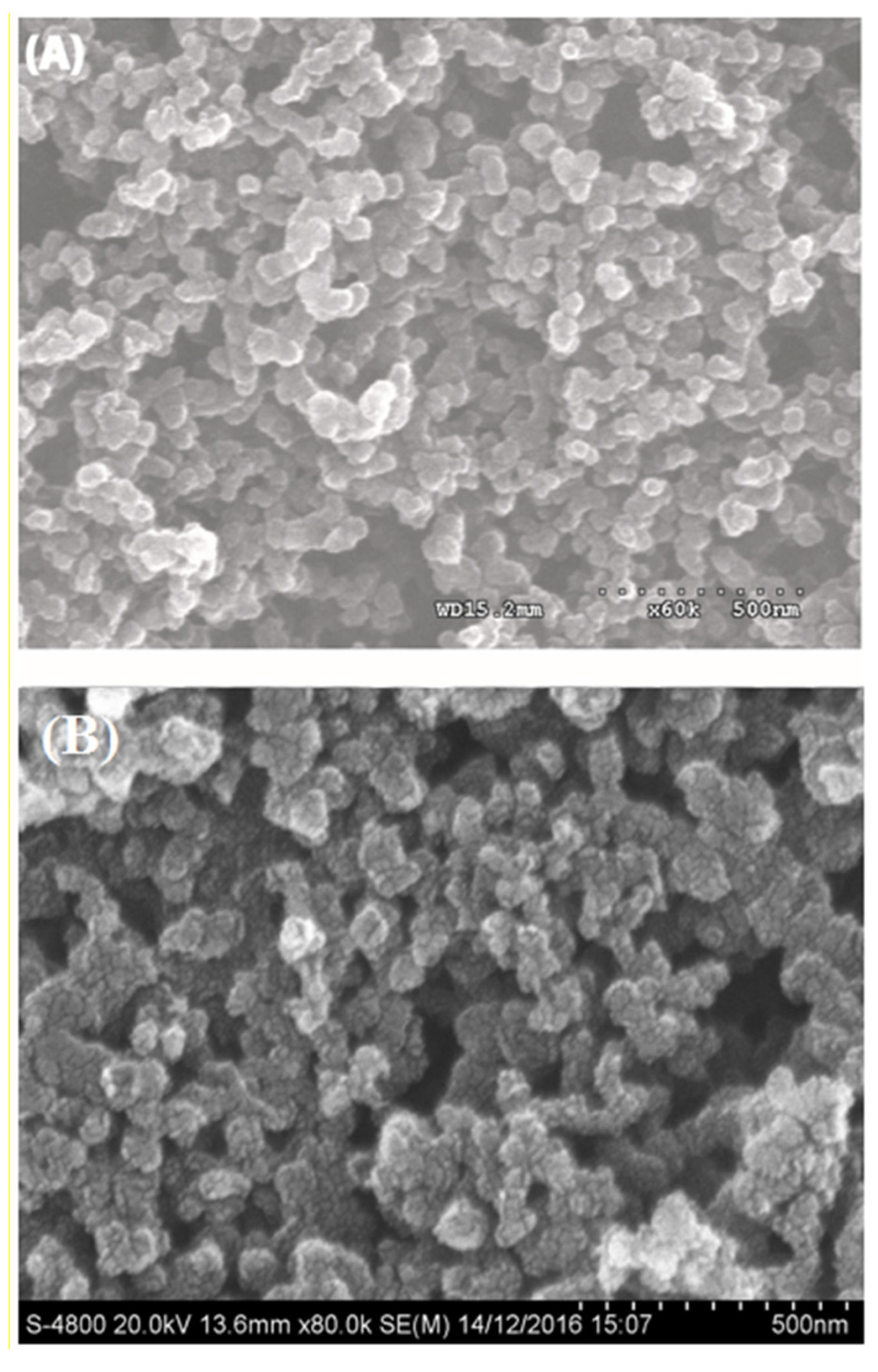
SEM images of Cs-Cu-sal/C modified PCE surface view (A) and pristine carbon particles (B).
3.1 Electrochemical characterization of Cs-Cu-sal/C
The cyclic voltammogram of Cs-Cu-sal/C electrode was recorded in 0.1M phosphate buffer (pH 7) under Ar, shown in Fig. 2(A). The modified electrode exhibited a set of redox peaks at 0.15 V and −0.17 V at the scan rate of 50 mV/s due to Cu(II) to Cu(I) couple [35]. The overlay of the cyclic voltammograms of Cs-Cu-sal/C film at scan rate of 10 mV/s to 200 mV/s indicated that the redox peak current and peak to peak separation were linearly increased with the increased in scan rate. Fig. 2(B) showed the linear dependence of the redox peak current to the scan rate, suggested that the charge transport through the film occurs under the surface confined phenomenon of electron transfer at Cs-Cu-sal/C electrode. Similar behavior was reported by Van Bui, for the ferrocene brushes modified electrodes [36]. This newly prepared Cs-Cu-sal/C film showed adequate stability in the aqueous solutions as the current of the peaks are not decreased on continuous cycles.
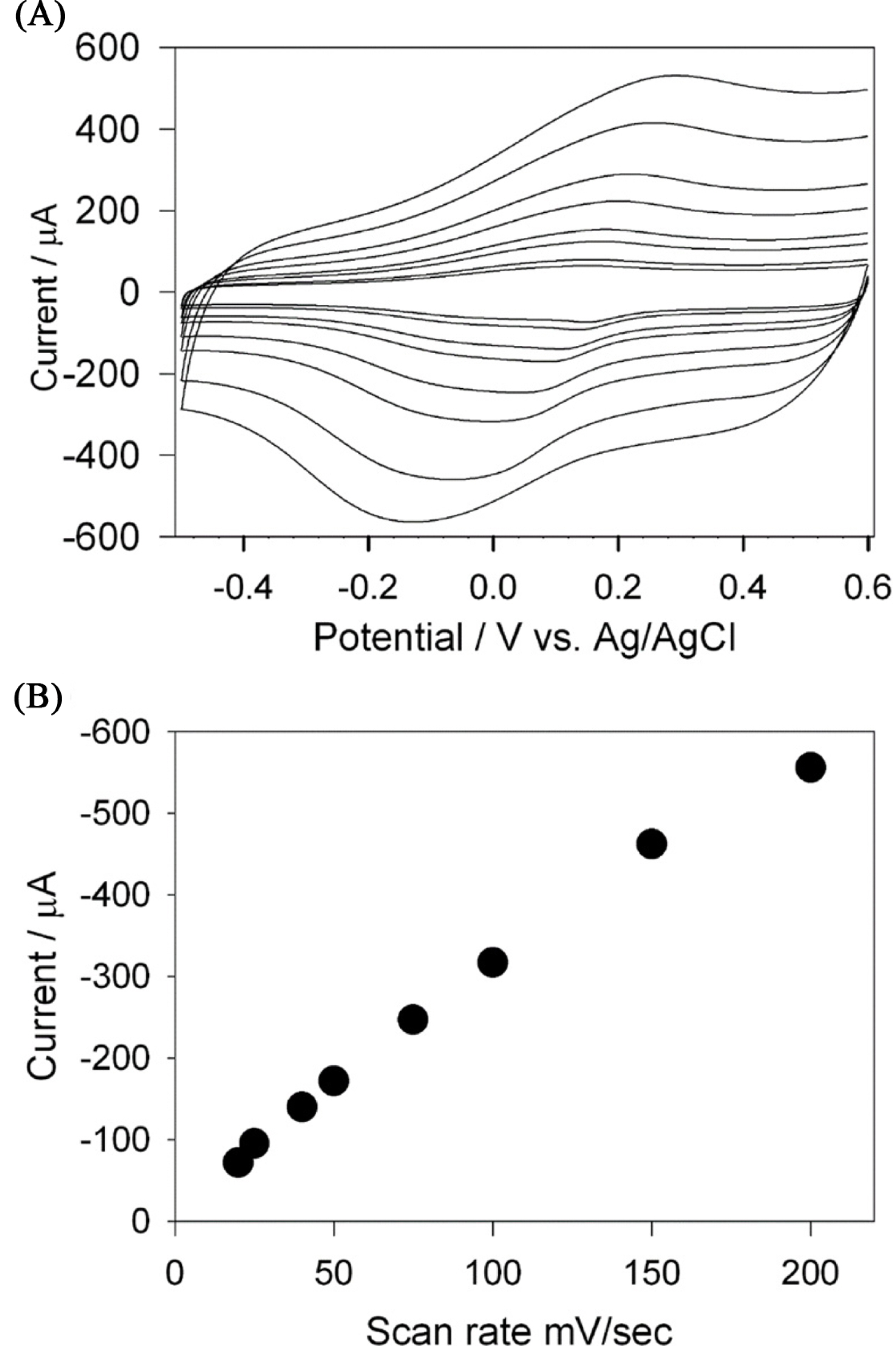
Cyclic voltammograms of the Cs-Cu-salen/C composite electrode in 0.1 M phosphate buffer at the scan rates of 20 mV/sec to 200 mV/sec (A) and plot of scan rate vs. current (B).
3.2 Electrocatalytic effect on reduction of hydrogen peroxide
The usefulness of the Cs-Cu-sal modified electrode for H2O2 sensing was further demonstrated by cyclic voltammetry. Cyclic voltammograms of the modified electrode were recorded in 0.1 M PB at pH 7 in the presence and absence of 5 mM H2O2 at the scan rate of 10 mV/sec (Fig. 3) under Ar. The current of the reduction peak of the Cu (II) to Cu (I) redox couple at −200 mV is increased in the presence of 5 mM H2O2 (dashed line) indicating the hydrogen peroxide reduction. The reduction of the hydrogen peroxide and the possible reaction mechanism is proposed as follows.

Cyclic voltammograms of Cs-Cu-sal/C modified PCE in 0.1 M phosphate buffer (solid line) and phosphate buffer with 5 mM H2O2 (dash line) at 10 mV/sec.


3.3 Effect of scan rate and pH
Effect of scan rates (ν) on the sensing of H2O2 in terms of catalytic currents was investigated in the range of 10 mV/s to 80 mV/s. Fig. 4(A) shows the CVs of the Cs-Cu-sal/C at different scan rates in the potential window of −0.6 to +0.5 V in PBS (pH 7.0). From Fig. 4(B), it can be observed that the cathodic peak currents varied linearly with the increase in scan rate and this indicates the surface confined electron transfer at the Cs-Cu-sal/C modified electrode surface. The effect of pH on the H2O2 reduction also checked by CV in the PB with pH ranges from 5 to 9 (Fig. 5(A)). Hydrogen peroxide reduction potential was slightly shifted with pH, while decreased in current was observed from pH 5 to pH 9 (Fig. 5(B)). The H2O2 reduction is the H+ dependent process accordingly there is shifting of the potential occurred as th pH of the phosphate buffer changes from pH 5 to pH 9 [37]. The modified electrode did not show significant change in the catalytic response when the pH was varied from 5 to 9 (variation in current response is within 5 μA). Though the modified electrode was stable in the investigated pH range, pH 7 was chosen as the working pH for further experiments as neutral pH is preferable for analyzing H2O2 in biological samples.
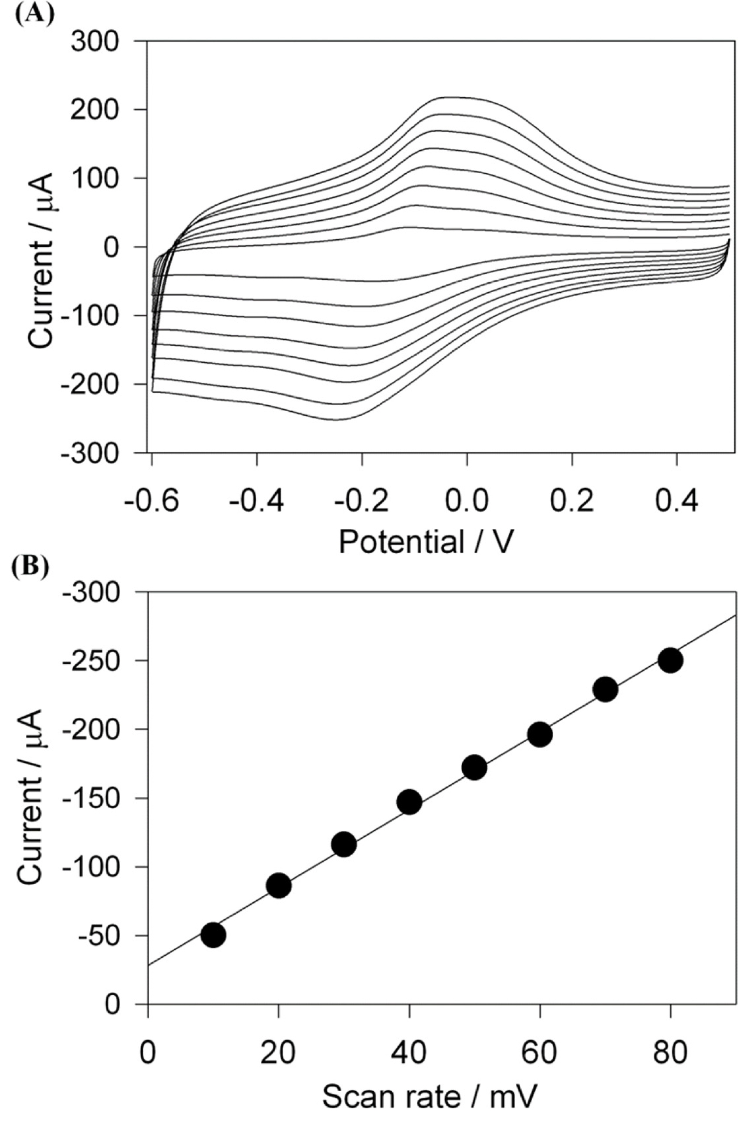
Cyclic voltammograms of Cs-Cu-sal/C modified PCE in 0.1 M phosphate buffer containing 1 mM H2O2 at the scan rate of 10, 20, 30, 40, 50, 60, 70, 80 mV/sec from inner to outer (A), and the cathodic peak current vs. scan rate (B).
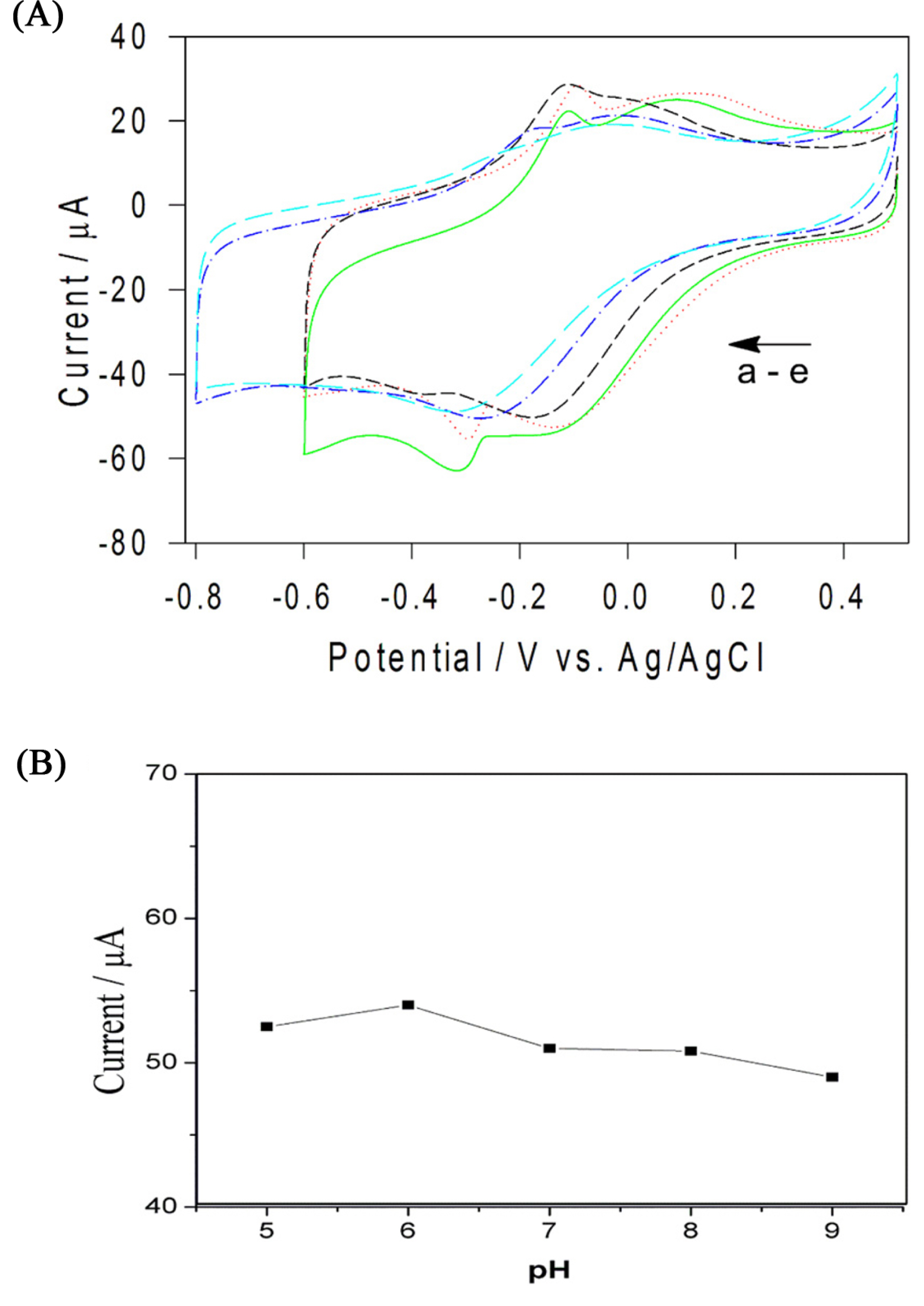
Cyclic voltammograms of Cs-Cu-sal/C modified PCE in 0.1 M phosphate buffer containing 1 mM H2O2 in pH 5 (red), 6 (green), 7 (black), 8 (blue), and 9 (cyan blue) respectively (A) and plot of cathodic peak current vs. pH (B).
3.4 Amperometric H2O2 detection
The amperometric hydrogen peroxide sensing was studied by typical current-time response of the biosensor for successive additions of H2O2 in the continuously stirred PB at an applied potential of −0.3 V under the optimized experimental conditions (Fig. 6(A)). The rapid H2O2 response was achieved when the H2O2 was added in the stirred phosphate buffer solution and achieved 95% of steady-current in 5 seconds. The plot of the hydrogen peroxide concentration vs. amperometric current (Fig. 6(B)) showed the linear range of hydrogen peroxide concentration from 5 × 10⁻⁶ M to 5 × 10⁻⁴ M and the detection limit of 0.9 mM with the sensitivity of 0.356 mA mM-1 cm-2. The present sensor exhibits a comparable detection limit, linear detection range and higher sensitivity than the recently reported electrodes for the detection of hydrogen peroxide in neutral aqueous solutions [34,35,38].
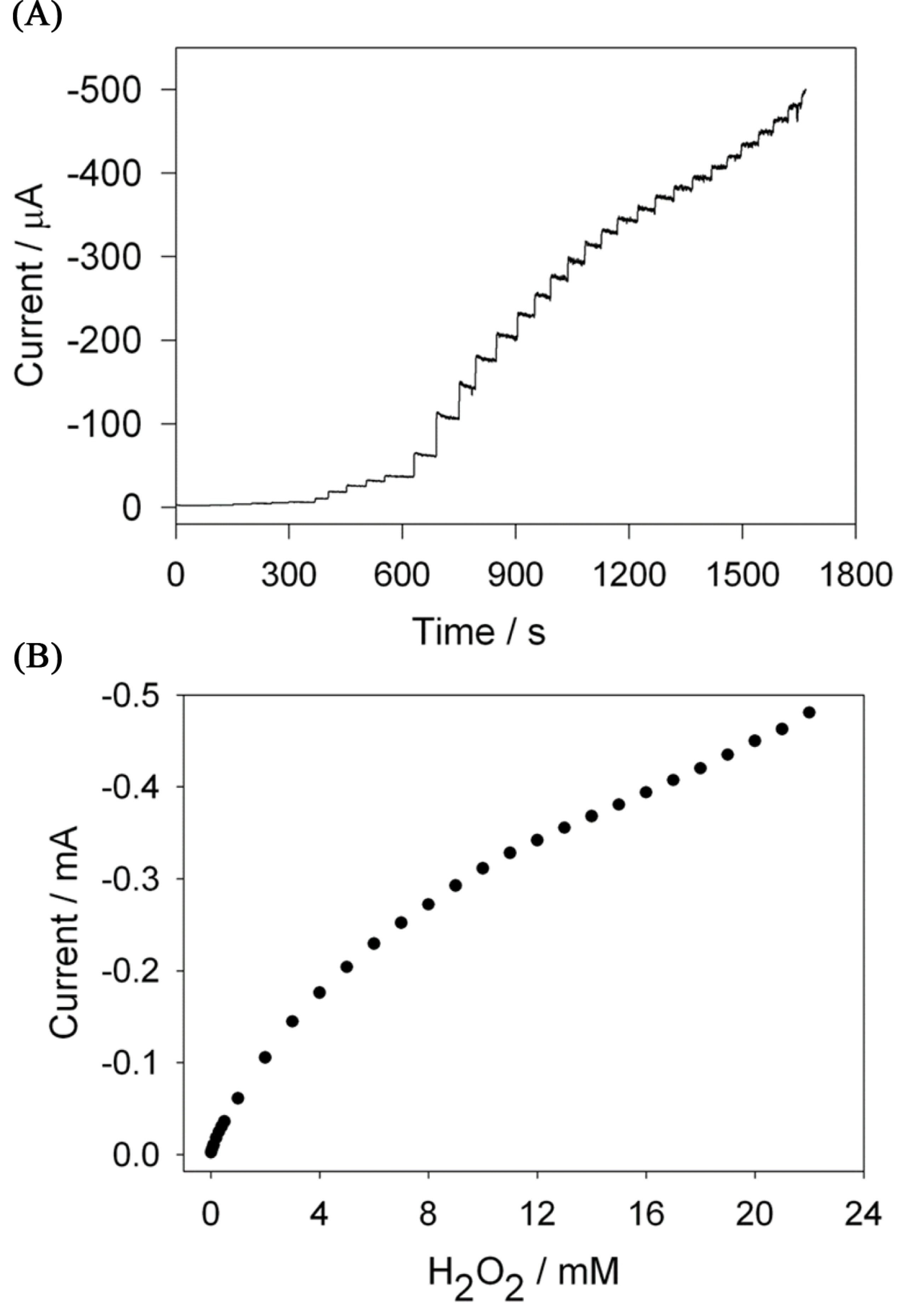
(A) The steady state current time response of Cs-Cu-sal/C modified PCE with successive injection of the H2O2 in to a stirred 0.1 M phosphate buffer at the applied potential of −0.3 V and (B) The plot of the current response to H2O2 added.
3.5 Effect of interferences and stability
It is known that the nitrate and ascorbic acid can be electrochemically reduced at the negative potential as of hydrogen peroxide and considered as an interference in the hydrogen peroxide sensing [38,39]. The effect of the interfering nitrate and ascorbic acid was examined by amperometric analysis. Fig. 7 shows the amperometric i-t curve at Cs-Cu-sal/C modified electrode in stirred phosphate buffer. Addition of 0.5 mM of H2O2 showed instant increase in the current (a) and followed by the addition equimolar ascorbic acid (b) and nitrate (c) solutions didn’t cause any effect on H2O2 peak current. The stability of the modified electrode was tested by subjecting to potential cycling in the presence and absence of H2O2. The modified electrode shown 5% relative decrease in peak current after 50 cycles in the absence of H2O2, while it exhibited 7.4% decrease in current response in the presence of H2O2. The stability data indicates the usefulness of the present electrode in the detection of hydrogen peroxide.
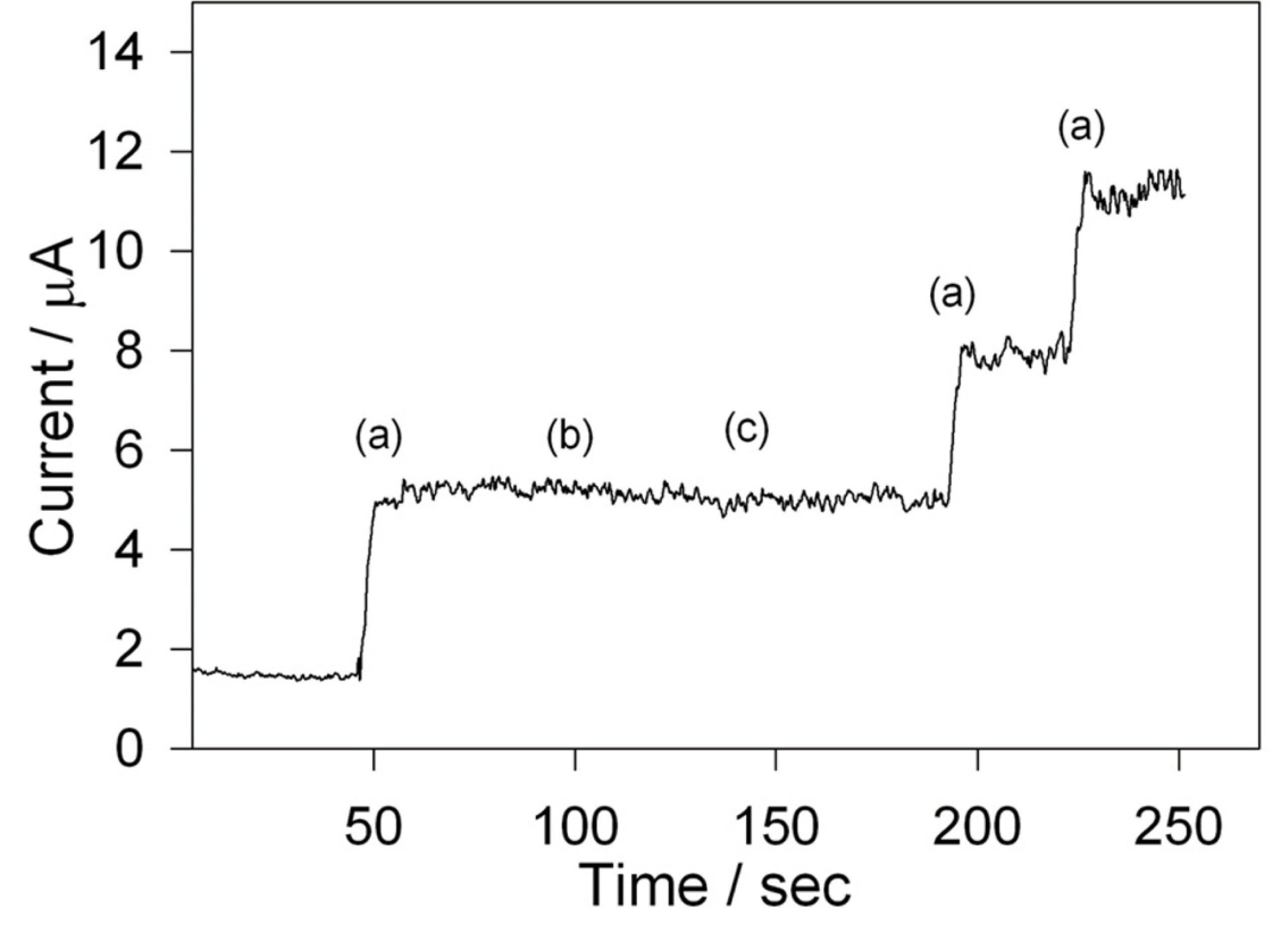
Effect of ascorbic acid (b) and nitrite (c) on the determination of H2O2 (a) with Cs-Cu-sal/C electrode in 0.1M phosphate buffer pH 7 at an applied potential of −0.3 V.
4. Conclusions
Cs-Cu-sal polymer and it’s composite with carbon nanoparticles were prepared. The composite film on the PCE electrodes was prepared by drop coating method. The modified electrodes was characterized and tested for the hydrogen peroxide sensing in neutral aqueous solutions. Method of sensor preparation and all the experimental results suggesting that the proposed electrode could be used for electrocatalytic H2O2 detection in real samples.
Acknowledgements
This research was supported by the Next-generation Medical Device Development Program for Newly-Created Market of the National Research Foundation (NRF) funded by the Korean government, MSIP (NRF-2015M3D5A1065760) to WS. HDJ is thankful to Science and Engineering Research Board (SERB), Government of India for the startup research grant (file no. SB/FT/CS-037-2014).