Investigation of Direct and Mediated Electron Transfer of Laccase-Based Biocathode
Article information
Abstract
Enzymatic fuel cells are promising low cost, compact and flexible energy resources. The basis of enzymatic fuel cells is transfer of electron from enzyme to the electrode surface and vice versa. Electron transfer is done either by direct or mediated electron transfer (DET/MET), each one having its own advantages and disadvantages. In this study, the DET and MET of laccase-based biocathodes are compared with each other. The DET of laccase enzyme has been studied using two methods; assemble of needle-like carbon nanotubes (CNTs) on the electrode, and CNTs/Nafion polymer. MET of laccase enzyme also is done by use of ceramic electrode containing, ABTS (2,2'-azino-bis [3-ethylbenzthiazoline-6-sulphonic acid]) /sol-gel. Cyclic voltammetric results of DET showed a pair of well-defined redox peaks at 200 μA and 170 μA in a solution containing 5 and 10 μM o-dianisidine as a substrate for needle-like assembled CNTs and CNTs-Nafion composite respectively. In MET method using sol-gel/ABTS, the maximum redox peak was 14 μA in the presence of 15 M solution o-dianisidine as substrate. The cyclic voltammetric results showed that laccase immobilization on needle-like assembled CNTs or CNTs-Nafion is more efficient than the sol-gel/ABTS electrode. Therefore, the expressed methods can be used to fabricate biocathode of biofuel cells or laccase based biosensors.
1. Introduction
Biofuel cells are a kind of fuel cells that oxidize the fuels by using biological catalysts such as whole microorganisms, isolated enzymes, or organelles [1]. Enzyme-based fuel cells can potentially use the specific enzymatic reactions, to convert chemical energy into electrical energy by immobilization of redox enzymes on the anode and cathode electrodes. In enzymatic biofuel cells, the electrons are generated by oxidation of substrate using enzymes, then transferred to the cathode electrode and complete the electrical circuit [2,3]. Enzymatic fuel cells employ either mediated electron transfer (MET) or direct electron transfer (DET). In MET, the mediator acts as an electron relay to transfer electrons from enzyme’s active site to the electrode surface. Therefore, the electrical connection is created between the active site of the enzyme and the electrode surface [4]. DET between the electrode and enzyme would eliminate need to redox mediators and also, over potentials caused by the mediator will be eliminated [5]. Is found [5- 7]. Multi-copper laccase is a glycoprotein with a molecular weight between 54 to 383kDa [8]. The enzyme contains four copper atoms (Cu2+). One of the copper atoms is in the enzyme surface and consists of a copper atom type 1 (T1). Also, there are a cluster of three coppers with a copper type 2 (T2) and coppers type 3 (T3) at depth of the enzymes. Copper T1, receives electron from the oxidized substrate and transfers it to the T2/T3 copper cluster. At this stage, copper T2 acts as a resource of electrons and copper T3 reduces oxygen to water [9-11]. In recent years, the usage of laccase enzyme has been greatly increased and its immobilization is a considerable issue. There are various methods for immobilization of laccase enzyme, including the use of nanoscale supports and a range of encapsulation and covalent methods [12-14]. Immobilized laccase in comparison with free enzyme has several advantages such as increased stability, facilitating recovery and purification of enzymes, enzyme reuse and continuous operation of enzymatic processes [4]. The applications of immobilized laccases are in the food industry, synthesis of pharmaceuticals [5], bleached pulp [11], labeled in safety assessment studies [15] and the other applications include development of cathodic catalysts of enzymatic fuel cells [9], and biosensors [10]. However, in order to optimize the performance of laccase-based biocathodes, the following parameters need to be improved: enzyme immobilization on the electrode surface, rate of electron transfer (ET), and operational stability of the bioelectrode [16]. In this work, we investigated the immobilization of Rhus vernificera laccase enzyme by three different methods compare with each other. The DET of laccase was studied using two methods. First, DET achieved by needle-like assembled and MWCNTs covalent binding onto electrode. Then, laccase immobilized using Nafion/MWCNTs. Also, MET of laccase was done by ABTS (2,2'-azino-bis [3-ethylbenzthiazoline-6-sulphonic acid]) as mediator while using silane sol-gel. Electrochemical behavior of the laccase-based biocathodes were investigated by cyclic voltammetry (CV).
2. Experimental Section
2.1. Materials
Multi-walled carbon nanotubes (MWCNTs), purity 95%, 200 nm long and 15 nm diameter were purchased from Nano times Co. (Chengdu, China), Sulfuric acid 98%, hydrogen peroxide 30%, ammonium sulfate, 1-3 Dicyclocarbodiimide (DCC), 1-Ethyl-3-(3-Dimethylaminopropyl) Carbodiimidehydrochloride (EDC), N-Hydroxy Succinimide (NHS), KH2−PO4, K2HPO4, HNO2 were all purchased from Merck (Darmstadt, Germany), 3-Aminopropyltrimethoxy silane 5%, Rhus vernificera laccase enzyme 120 U/mg, 2,2'-azino-bis (3-ethylbenzthiazoline-6-sulphonic acid) (ABTS), Nafion 5% (Nafion ®), graphite powder (MO-300), o-dianisidine were obtained from Sigma-Aldrich (St. Louis, MO, USA), Tetramethoxysilane (TMOS) and methyltrimethoxysilane (MTMOS) were purchased from Aldrich (Milwaukee, WI, USA). All solutions were prepared with deionized water passed through a purification system.
2.2. Cyclic Voltammetry
All electrochemical measurements were performed at room temperature, with Potentiostat Galvanostat (Drop Sens model DRP-STAT 200) in a conventional three-electrode cell of volume 20 mL, which included glassy carbon (diameter = 5 mm) as the working, platinum wire as the counter and Ag/AgCl as the reference electrodes. At the start of the CV experiments, nitrogen was bubbled through the solution for 30 min. In order to confirm the reproducibility of results, all experiments were performed triplicate in static systems and three times in each concentration of substrate.
2.3. Fabrication of biocathode by using Needle-like assembled MWCNTs
2.3.1. Functionalization of CNTs
In this stage, 2 mg of MWCNTs was added to 10 mL mixture of concentrated sulfuric acid and nitric acid (3:1 v/v, 98%, and 70%, respectively), then sonicated for 4 h in a water bath at 50°C and 55 kHz. At the end, the reaction mixture was diluted with DDW (Double-distilled water) and washed till neutral pH was achieved [17]. Therefore, the oxidation of CNTs by acid and formation of CO2 caused the formation of carboxyl groups in the end of CNTs.
2.3.2. Electrode Preparation
Amine functionalization of electrode was done in two steps. First, glassy carbon electrode was cleaned and carboxyl group was formed by performing CV from −1.3 to 1.3 V for 12 sweep segments at a scan rate of 0.1 V/s in a solution containing 7:3 v/v, H2SO4 98%, H2O2 30%. The electrode was rinsed and then allowed to dry overnight before further modification. Then the amino-terminated monolayer was obtained by placing cleaned carboxylated glassy carbon electrode into 1 wt% solution of 3-aminopropyltrime-thoxysilane and APS (ammonium persulfate) in toluene for 24 h at room temperature, expecting the 3-aminopropyltrimethoxysilane attaches covalently to carboxyl group formed in the surface of glassy carbon electrode while amine group is accessible. Then the functionalized substrates were washed sequentially with toluene, and DDW to eliminate any possible physically absorbed impurities. To fabricate needle-like assembled MWCNTs on the (amine functionalized) glassy carbon, the amino terminated carbon was placed into a carboxyl-terminated MWCNT/DMF (Dimethylformamide) suspension with the aid of a condensation agent, DCC, for overnight at room temperature. Thus MWCNTs attached to the surface of glassy carbon electrode, while carboxyl groups are accessible. MWCNT/DMF solution is prepared by sonication of 1 mg MWCNTs in 1 ml of DMF solvent for 3-5 h [18].
The CNTs then incubated at 25°C in EDC (200 mM) and NHS (50 mM) for 1 h to form reactive esters from the carboxylic acid groups. laccase (1 mg/mL in 100 mM sodium phosphate buffer, pH 5.0) was then added and allowed to covalently link to the functionalized nanotube via carboxyl-amine coupling, incubating for 2 h at 25°C [19]. Immobilization process to fabricate bioelectrode is summarized in (Fig. 1). After enzyme immobilization, the electron transfer of enzyme were measured by placing the fabricated biocathode in different concentrations of o-dianisidine, phosphate buffer 0.2 M, pH 5 using Potansio galvanometer Drop Sens and CV method.

Connection of laccase enzyme to CNTs. a: Needle-like assembled MWCNTs on the electrode b: Connection of laccase to needle-like assembled MWCNTs.
2.4. Fabrication of biocathode by using Nafion/MWCNTs
The electrode surface is rinsed by DDW then, 10 μL of MTMOS was dropped on the electrode. After drying, 10 μL of MWCNT/DMF suspension (1 mg/mL) was used, followed by drying 20 μL of laccase enzyme (1 mg/mL) casted on the working electrode. 10 μL of Nafion 5% was dropped on the electrode surface and the CV experiment was done after drying the electrode.
2.5. Fabrication of biocathode by encapsulation of laccase in Sol-gel
In this method, fabrication of biocathode involves two steps. First, fabrication of the ceramics containing ABTS electrode was performed. Second, encapsulation of the enzyme in hydrophilic gel (TMOS gel) was done.
2.5.1. Fabrication of ceramic electrode containing ABTS
First, hydrophobic sol must be prepared and 1 mL of MTMOS was mixed with 1.5 mL of methanol. Then, 12 mg of ABTS and 50 μL of the acid chloride 11 mol d m−3 were added to the mixture, and the whole suspension was subjected to sonication for 2 min, to become completely smooth. Then, 12.5 g of graphite powder was added to the resulting solution and was sonicated for 1 min. Finally, the resulting mixture placed on a glass container with dimensions of 2×2×2 cm3, fixing a copper wire in the solution and was left at room temperature for 48 h to dry.
2.5.2. Encapsulating the enzyme with TMOS gel
In order to fabricate TMOS gel, TMOS, H2O and 0.04 mol dm−3 aqueous solution of HCl were mixed (18: 4.5: 1). The mixture was sonicated for 20 min, and then was diluted with water (1: 1) After 3 min sonication, the resulting mixture was diluted again with water (1: 100), followed by sonication for 3 more minutes. Finally, 1 mg of laccase enzyme was added to 1 ml diluted solution, and then 20 μl of the enzyme-sol was dropped onto ABTS-ceramic electrode surface and dried at room temperature for 24 h [20]. In this case and in contrast to two another different methods with DET, a mediator acts as a redox system and shuttle electron between the enzyme and the electrode. A schematic of a direct and mediated electron transfer is depicted below in Fig. 2.
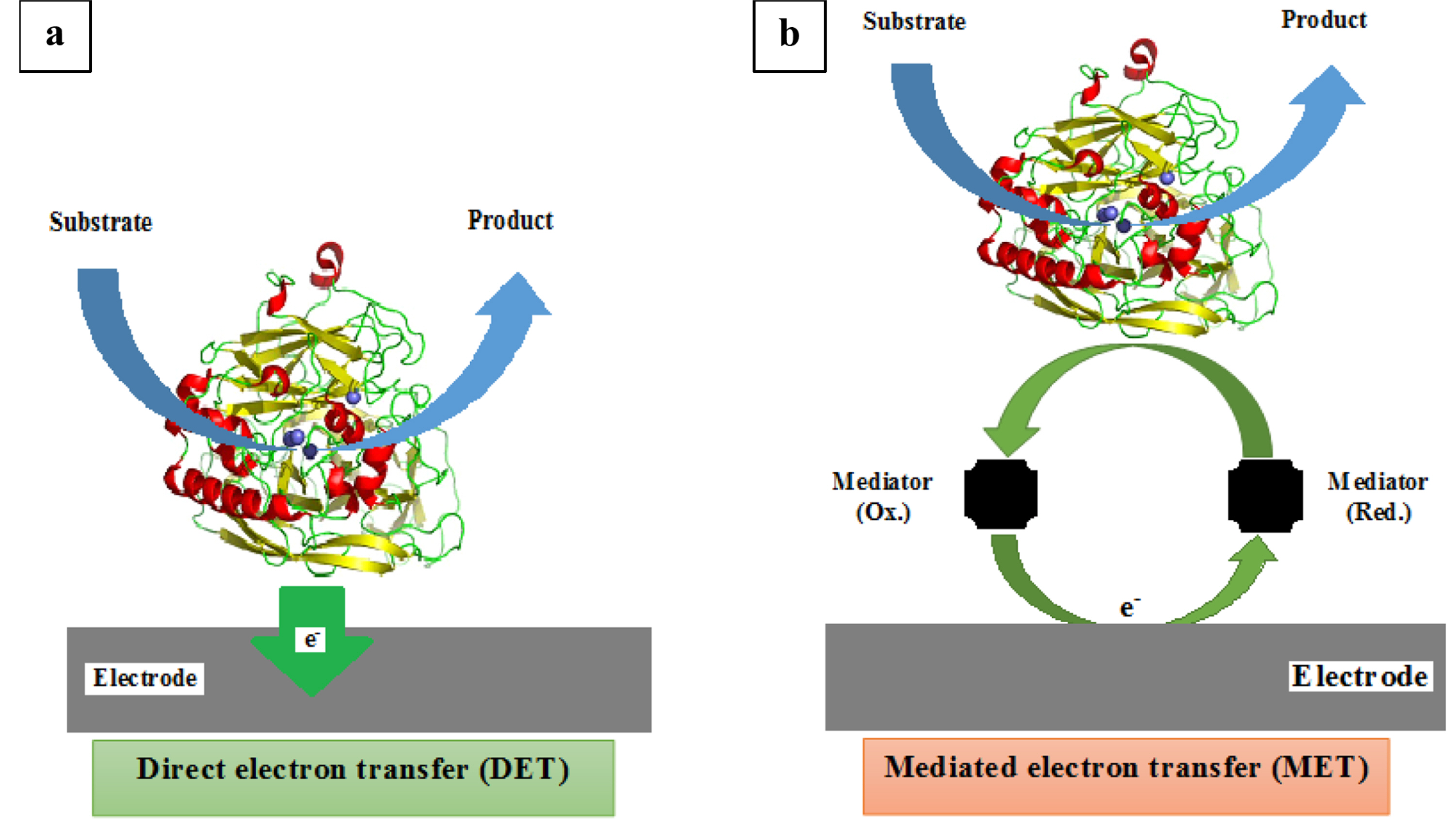
Schematic illustration of electron transfer mechanism between an enzyme and an electrode performing by a: direct or b: mediated electron transfer process.
3. Results and Discussion
3.1. Biocathode prepared by Needle-like assembled MWCNTs
Cyclic voltammogram of fabricated cathode by using of needle-like assembled MWCNTs at a scan rate of 0.1 V/s with the potential range between −0.8 and 1.2 V in phosphate buffer 0.2 M, pH 5 at 25°C and 0.1 M o-dianisidine solution showed no redox peak (Fig. 3-a). Consequently, redox peaks were achieved when laccase was immobilized on the electrode surface. Voltammogram of the fabricated bioelectrode in the presence of 2.5 nM o-dianisidine and at a scan rate of 0.1 V with the potential range between −0.8 and 1.2 V in a potassium phosphate buffer 0.2 M and pH 5 is shown in Fig. 3-b. According to the Fig. 3-b, just one current peak, at the voltage of 0.7 versus Ag/AgCl is observed with the maximum current of 5 μA. The voltammogram is cyclic and just one specific peak is observed, it indicates the irreversible electron transfer of laccase. Voltammogram of the fabricated bioelectrode in the presence of 0.3 μM o-dianisidine at a scan rate of 0.1 V/s with the potential range between −0.8 and 1.2 V in phosphate buffer 0.2 M, pH 5 at 25°C, is shown in Fig. 3-c. The CV curve gives a pair of broad current peaks while the oxidation peak is recorded at 0.45 V versus Ag/AgCl and the maximum current is obtained at 45 μA. Also reduction peak is achieved at −0.25 V versus Ag/AgCl with a minimum current of −40 μA. The current peaks indicate the DET of laccase to the electrode and the ability of MWCNTs to facilitate electron transfer between laccase and electrode surface. The wide distance between reduction and oxidation peaks (0.7 V) is observed but electron transfer rate is significantly slow. In 0.3 μM o-dianisidine, there is a slight gap between oxidation and reduction peak with a pair of broad current peaks. This concentration of o-dianisidine can be considerate as detection limit of fabricated biocathode.
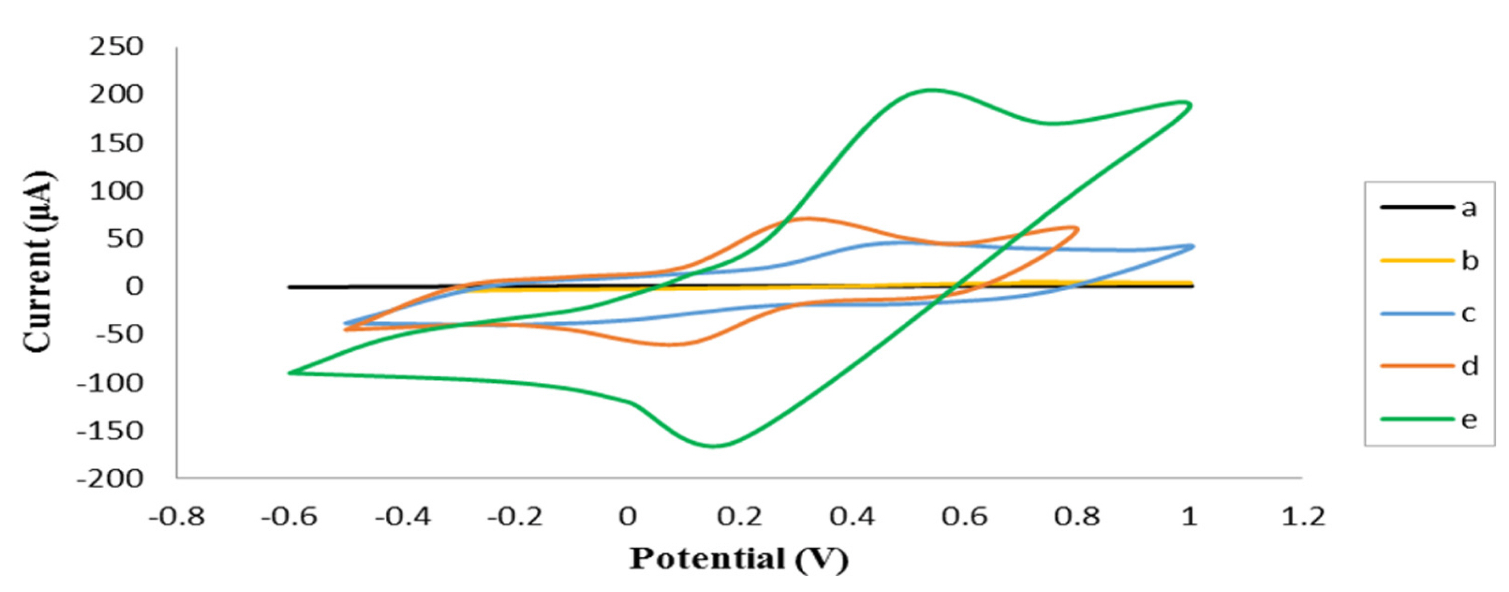
Cyclic voltammogram of the laccase immobilized on needle-like assembled MWCNTs at a scan rate of 0.1 V/s in potassium phosphate buffer 0.2 M, pH 5 at 25°C, with or without enzyme at various concentrations of substrate a: 0.1 M o-dianisidine (no enzyme), b: 2.5 nM o-dianisidine, c: 0.3 μM o-dianisidine, d: 1 μM o-dianisidine, e: 5 μM o-dianisidine concentration.
To investigate the bioelectrode response to the substrate concentrations, the CV curves were recorded in various concentrations of o-dianisidine solution at a scan rate of 0.1 V/s. Fig. 3-d and 3-e depict the CV curves recorded in phosphate buffer 0.2 M, pH 5 at 25°C, with the potential range between −0.8 and 1.2 V, at 1 μM and 5 μM o-dianisidine solution respectively. In 1 μM o-dianisidine solution, the CV curve gives a pair of sharp and well-defined current peaks. The oxidation peak was at 0.3 V versus Ag/AgCl and the maximum current at 70 μA. The reduction peak was achieved at 0.1 V versus Ag/AgCl with the minimum current at −60 μA. It indicates the efficient electrical connection between active site of laccase and electrode surface. A pair of sharp current peaks was obtained in 1 μM o-dianisidine solution. It indicates that the bioelectrode undergoes reasonable response to the substrate concentration. In addition, sharper slope of the achieved curve indicates the high rate of electron transfer compared to lower concentrations. Also, as reversible reaction is done, the potential difference between reduction and oxidation peak is decreased to 0.2 V. CV of different concentrations of substrate was done when the maximum current is recorded in 5 μM o-dianisidine solution (Fig. 3-e). In 5 μM o-dianisidine solution, the CV curve gives a pair of sharp and well-defined current peaks where oxidation peak was observed at 0.5 V versus Ag/AgCl and the maximum current was at least 200 μA (more than 200 μA is not measurable by Drop sens). The reduction peak was achieved at 0.2 V versus Ag/AgCl with the minimum current of - 160 μA. It shows the efficient electrical connection between active site of laccase and electrode surface. In addition, redox peaks in this concentration is sharper than lower concentrations of o-dianisidine. The potential difference between reduction and oxidation peaks is decreased to 0.3 V. These results show fabricated biocathode by using needle-like assembled MWCNTs can undergo the DET at concentrations of 0.3 μM to 5 μM o-dianisidine in phosphate buffer 0.2 M, pH 5 and 25°C. The maximum current peak is achieved in 5 μM o-dianisidine and it can be the optimum concentration of substrate for fabricated biocathode.
In order to investigate the ET mechanism at the fabricated electrode, the voltammograms of electrode were recorded in phosphate buffer 0.2 M, pH 5 and 25°C at different scan rates of 0.1, 0.2, 0.3, 0.4, 0.5 V/s. Results showed the peak current changes at different scan rates have a linear form. Indicating enzyme attached to the electrode, monolayer with covalently bound. This is the same as Laviron’s model that created a uniform surface without adverse interactions. Therefore, electrode behaves like Butler-Volmer electrode kinetic model and continued rapid electron transfer between enzyme and electrode [21] (data not shown).
3.2. Biocathode prepared by Nafion and MWCNTs
Furthermore, the cyclic voltammograms of fabricated cathode by using of Nafion and MWCNTs were studied. In the previous method, enzyme was immobilized by employing chemical techniques. Since, chemical immobilization methods may affects enzyme activity, a physical method (entrapment of enzyme) was studied too. For this purpose, laccase was entrapped by Nafion polymer. As Nafion is a proton exchange polymer but is not an electron conductive, the MWCNTs were also used to facilitate electron transfer of laccase. The cyclic voltammogram of fabricated biocathode using Nafion and MWCNTs at a scan rate of 0.1 V/s with the potential range between −0.6 and 1.2 V in 0.1 M o-dianisidine solution showed no redox peak (Fig. 4-a). Consequently, the redox peaks were obtained when laccase was immobilized on the electrode surface. In Fig. 4-b, cyclic voltammogram of fabricated biocathode by using Nafion and MWCNTs is recorded in potassium phosphate buffer 0.2 M, pH 5 at 25°C, scan rate 0.1 V/s with the potential range between −0.6 and 1.2 V and 5 μM concentrations of o-dianisidine. It shows a pair of sharp and well-defined current peaks with oxidation peak of 0.5 V versus Ag/AgCl and the maximum current of 60 μA. The reduction peak was achieved at −0.2 V versus Ag/AgCl with the minimum current at −55 μA. The results show efficient electrical connection between active site of laccase and electrode surface but needle-like assembled MWCNTs are more efficient. In addition, the potential difference between reduction and oxidation peaks is increased to 0.7 V. In contrast to the previous method, irregular shifting of the reduction peak to negative area is occurred. It caused by non-ideal oriented enzymes that are not able to catalyze the reversible enzymatic reaction at the regular potential. In Fig. 4-c, cyclic voltammogram of fabricated biocathode by using Nafion/MWCNTs is recorded in potassium phosphate buffer of 0.2 M, pH 5, at 25°C, scan rate 0.1 V/s with the potential range between −0.6 and 1.2 V and 10 μM of o-dianisidine. It shows a pair of sharp and well-defined current peaks with oxidation peak at 0.32 V versus Ag/AgCl and the maximum current of 170 μA. The reduction peak was achieved at 0.2 V versus Ag/AgCl with the minimum current of −45 μA. By increasing concentration of substrate from 5 μM to 10 μM potential shifting of reduction peak is improved and the potential difference between reduction and oxidation peaks is decreased to 0.12 V. The results show DET between the enzyme and the electrode is possible when enzyme is immobilized by Nafion/MWCNTs. But, the covalent bonding of enzyme to the electrode causes more efficient DET compared to physical immobilization. It may occur because ideal orientation of enzymes is more feasible when enzymes are immobilized monolayer on the needle-like assembled MWCNTs. It leads to high electron transfer rate with sharper and higher redox peaks without any irregular shifting.

Cyclic voltammograms of the laccase immobilized using Nafion and MWCNTs at scan rate of 0.1 V/s, potassium phosphate buffer 0.2 M, pH 5 and 25°C, in the presence of a: 0.1 M o-dianisidine (no enzyme), b: 5 μM o-dianisidine, c: 10 μM o-dianisidine.
In Fig. 5 a Scanning electron microscope(SEM) of MWCNT (a), Nafion-MWCNT (b) and Nafion-enzyme-MWCNT on electrode (c) are shown.

SEM images of electrode surfaces covered by: a: MWCNT, b: Nafion-MWCNT c: Nafion-enzyme- MWCNT.
3.3. Biocathode prepared by encapsulation of laccase in Sol-gel
Furthermore, the cyclic voltammograms of fabricated biocathode by using the encapsulation of laccase in sol-gel as a physical method were studied. In two previous methods the DET of laccase was analyzed, though in this section the MET of laccase using ABTS−2 as mediator is studied. The cyclic voltammogram of fabricated biocathode using sol-gel and ABTS−2/ceramic electrode, at a scan rate of 0.1 V/s with the potential range between 0 and 0.8 V in 0.1 M o-dianisidine solution showed no redox peak (Fig. 6-a). Consequently, redox peaks were obtained when laccase was immobilized on the electrode. The cyclic voltammogram of fabricated biocathode using encapsulated laccase in sol-gel and ABTS−2/ceramic electrode, at a scan rate of 0.1 V/s with the potential range between 0 and 0.8 V in 15 μM o-dianisidine solution is shown in Fig. 6-b. It shows a pair of broad (not sharp) and well-defined current peaks with oxidation peak of 0.41 V versus Ag/AgCl and the maximum current of 11 μA. The reduction peak was achieved at 0.34 V versus Ag/AgCl with the minimum current of −11 μA. A pair of well-defined current peaks indicates the encapsulated enzyme can undergo MET of enzyme by using ABTS−2. The potential difference between reduction and oxidation peaks decreases to 0.07 V. It shows encapsulated enzymes are able to catalyze a reversible reactions compared to previous methods. A pair of broad and well-defined current peaks indicates that enzyme catalysis is facilitated by mediator however electron transfer rate is low. It may occur due to unsuitable orientation of enzymes or imperfect electrical connection between active site of enzyme and electrode surface. In this method, by increasing the concentration of substrate no significant changes were observed in peaks. Therefore, unsuitable orientation of enzymes may not be occurred. In addition, a potential limitation of encapsulation methods is physical separation of enzyme-mediator or enzyme-electrode. It can prevent the effective shuttling of electrons between the enzyme and electrode. MWCNTs have been used in numerous researches to improve electrical connection of enzymes to electrodes. In order to investigate the electrical connection between active site of enzyme and electrode surface, 100 μL MWCNTs was added to the surface of the constructed ceramic electrode. After drying, fabrication of the biocathode was done as before. By adding MWCNTs, the CV curves show higher current peaks or sharper redox peaks. It can be expected the main cause of non-proper function of the biocathode is just the imperfect electrical connection between active site of enzyme and electrode surface. It means that the enzyme immobilization process has no significant effect on the structure and activity of enzyme. The cyclic voltammogram of fabricated biocathode by using encapsulation of laccase in sol-gel and MWCNTs/ceramic electrode containing ABTS−2, at a scan rate of 0.1 V/s with the potential range between 0 and 0.8 V in 15 μM o-dianisidine solution is shown in Fig. 6-c. In 15 μM o-dianisidine solution, the CV curve gives a pair of well-defined current peaks with oxidation peak of 0.38 V versus Ag/AgCl and the maximum current of 14 μA. The reduction peak was achieved at 0.32 V versus Ag/AgCl with minimum current of −12 μA. In addition, redox peaks in MWCNTs/ABTS−2/ceramic bioelectrode are sharper than ABTS−2/ceramic bioelectrode. It shows the electrical connection between active site of laccase and electrode surface is improved by MWCNTs. The potential difference between reduction and oxidation peaks is decreased to 0.06 V. These results showed fabricated biocathode by using ABTS−2/ceramic bioelectrode can undergo MET of laccase. Also, MWCNTs can improve imperfect electrical connection between the enzyme and the electrode surface. Therefore, the electron transfer rate is increased and the redox peaks are higher and sharper. In Fig. 6-b and Fig. 6-c both curves are obtained in the same concentration of the substrate (15 μm o-dianisidine). But in Fig. 6-b, the electrical communication between the enzyme and the electrode surface is not perfect and the maximum current peak is at 11 μA. The modification of electrode surface by adding the MWCNTs improves electrical connection between enzyme and the electrode surface. So, more electrons are transferred from enzyme to the electrode surface. Thus, the resulting redox peaks at the same concentration are at 14 μA. The redox peak at 14 μA indicates immobilization of enzyme in sol-gel with no significant influence on the structure and activity of the enzyme. The imperfect contact between enzyme and the electrode surface lead to malfunction of fabricated biocathode and any additional method is needed to improve this electrical connection.

Cyclic voltammograms of the laccase immobilized in sol-gel at scan rate of 0.1 V/s, potassium phosphate buffer 0.2 M, pH 5 at 25°C, in a: 0.1 M o-dianisidine (no enzyme), b: 15 μM o-dianisidine c:15 μM o-dianisidine with use of CNTs.
In summary, three different enzyme immobilization systems were tested: (i) the covalent connection by Needle-like assembled MWCNTs, (ii) entrapment (Nafion) and (iii) encapsulation by sol-gel. The results obtained from the CV technique in the laccase immobilization method and also comparison of these three methods are summarized in Table 1. On the basis of data shown in Table 1, we can assess that the Needle-like assembled MWCNTs is the best configuration to optimize the biocathode performances. Taken together, it can be concluded that the best enzyme immobilizing strategy is the covalent technique.
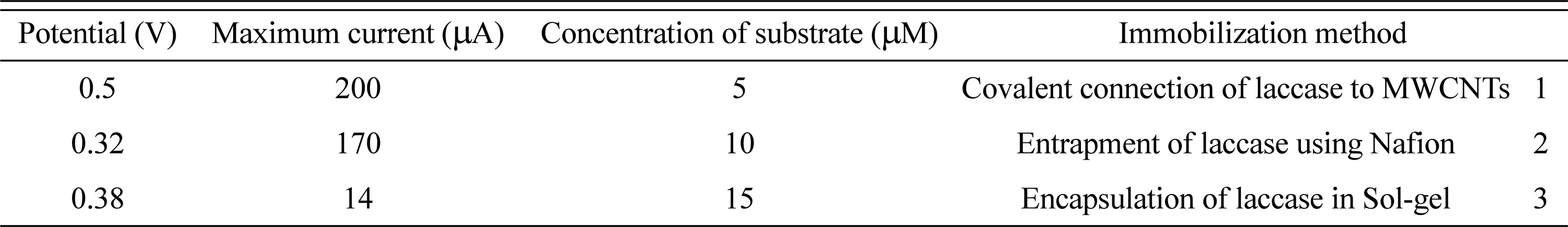
Comparison of parameters obtained from three different methods for immobilization of laccase enzyme.
4. Conclusions
According to the results, laccase undergoes both DET and MET. Fabricated biocathode by using needle-like assembled MWCNTs can undergo DET in wide range of substrate and shows higher efficiency in electron transferring compared to the Nafion/MWCNTs and sol-gel respectively. Results show the proper electrical connection between enzyme and electrode is the main factor for both DET and MET. The needle-like assembling of MWCNTs on the electrode surface provides perfect connection and high efficiency in DET compared to less proper connections by Nafion/MWCNTs and sol-gel respectively. In physical methods, physical separation of enzyme-mediator or enzyme-electrode can prevent the effective shuttling of electrons between the enzyme and electrode surface. CNTs can improve the electrical connections between the enzyme and electrode. Using sol-gel to the enzyme immobilization prevents effective electrical communication between enzyme and electrode but it does not effect on the enzyme activity. Each method that improves the electrical connection between electrode and enzyme may leads to increase in efficiency of biocathode. In this study, MET and DET of laccase was done while different immobilization methods such as covalent, entrapment and encapsulation were studied. As a result, the immobilization methods introduced in this paper are proposed as efficient methods to fabricate biocathode for biofuel cells or laccase based biosensors.