1. Introduction
Lithium-ion batteries are currently considered as the most efficient power source for a wide range of applications, such as small power-supply systems for portable electronic devices and large batteries for renewable energy-storage systems and electric vehicles
[1-
8]. Their electrochemical characteristics, such as capacity, rate capability, cycle life, and safety, are highly dependent on the cathode material
[9-
16]. Thus, the study of advanced cathodes has become one of the most important subjects in the development of high-performance lithium-ion batteries
[17-
21]. Ni-based cathode materials (e.g., Li[Ni
0.8Co
0.15Al
0.05]O
2) have received great attention because of their high discharge capacity and low cost. However, there are still problems such as low rate capability, unstable cyclic performance, and low thermal stability that must be overcome to achieve stable and high-performance lithium-ion batteries
[22-
25].
Surface modification by coating with stable materials (such as oxides, phosphates, and fluorides) is an effective approach to enhance the electrochemical performance of cathode materials
[26-
35]. AlF
3 [36], SiO
2 [37], and Ni
3(PO
4)
2 [38] have been used to modify the surface of Ni-based cathode materials. A stable coating layer can prevent undesired side reactions between the cathode and the reactive electrolyte, and improve the electrochemical properties and stability of the cathode material. In this study, Li
2SiO
3, a solid electrolyte with high ionic conductivity, was used as a coating material for the Ni-based cathode Li[Ni
0.8Co
0.15Al
0.05]O
2. Li
2SiO
3 coatings have been successfully applied to other cathode materials
[39-
41]. This solid-electrolyte coating is expected to facilitate the movement of lithium ions in the cathode interface and protect the surface of the cathode from the reactive electrolyte. Therefore, surface modification with Li
2SiO
3 may result in the formation of a stable coating layer with protective properties and lead to the enhancement of the rate capability and stability of the Li[Ni
0.8Co
0.15Al
0.05]O
2 cathode.
2. Experimental Section
Commercial pristine Li[Ni0.8Co0.15Al0.05]O2 (ECO-PRO) was used as the cathode material. The Li2SiO3 coating layer was prepared from an ethanol coating solution obtained by diluting lithium ethoxide and tetraethyl orthosilicate in ethanol. The mixture was stirred for 24 h at room temperature to obtain a homogeneous solution and the as-prepared Li[Ni0.8Co0.15Al0.05]O2 was then added. The mixture was heated to evaporate all of the solvent, and the residue was dried at 80┬░C for 24 h and then heated at 800o┬░C for 1 h to obtain an amorphous Li2SiO3 coating layer. The coating amount was adjusted to either 0.25 wt% or 0.5 wt% of the pristine cathode.
Pristine and coated samples were characterized by X-ray diffraction (XRD, Rigaku) using monochromatic Cu K╬▒ radiation (╬╗ = 1.5406 ├ģ), and their morphologies were observed by field emission scanning electron microscopy (FE-SEM, Nova Nano 200). For electrochemical testing, a cathode slurry was prepared by mixing Li[Ni0.8Co0.15Al0.05]O2 (pristine and Li2SiO3-coated), carbon black (Super P), and polyvinylidene fluoride in a weight ratio of 8:1:1, respectively. The mixed slurry was coated on the surface of an Al foil using a doctor blade and then dried at 90┬░C for 24 h. Coin-type cells (2032) were fabricated using a cathode, a separator, a Li-metal anode, and an electrolyte (1 M LiPF6 in ethylene carbonate/dimethyl carbonate (1:1 v/v)). The cells were subjected to galvanostatic cycling (WonATech voltammetry system) over a 3.0-4.5 V voltage range at various charge-discharge rates. Impedance measurements were performed by applying an AC voltage (5 mV amplitude, 100 kHz to 0.1 Hz frequency range) using an electrochemical workstation (AMETEK, VersaSTAT 3). The thermal stability of the charged (4.5 V) electrodes was analyzed by differential scanning calorimetry (DSC, Mettler Toledo) using a high-pressure DSC pan.
3. Results and Discussion
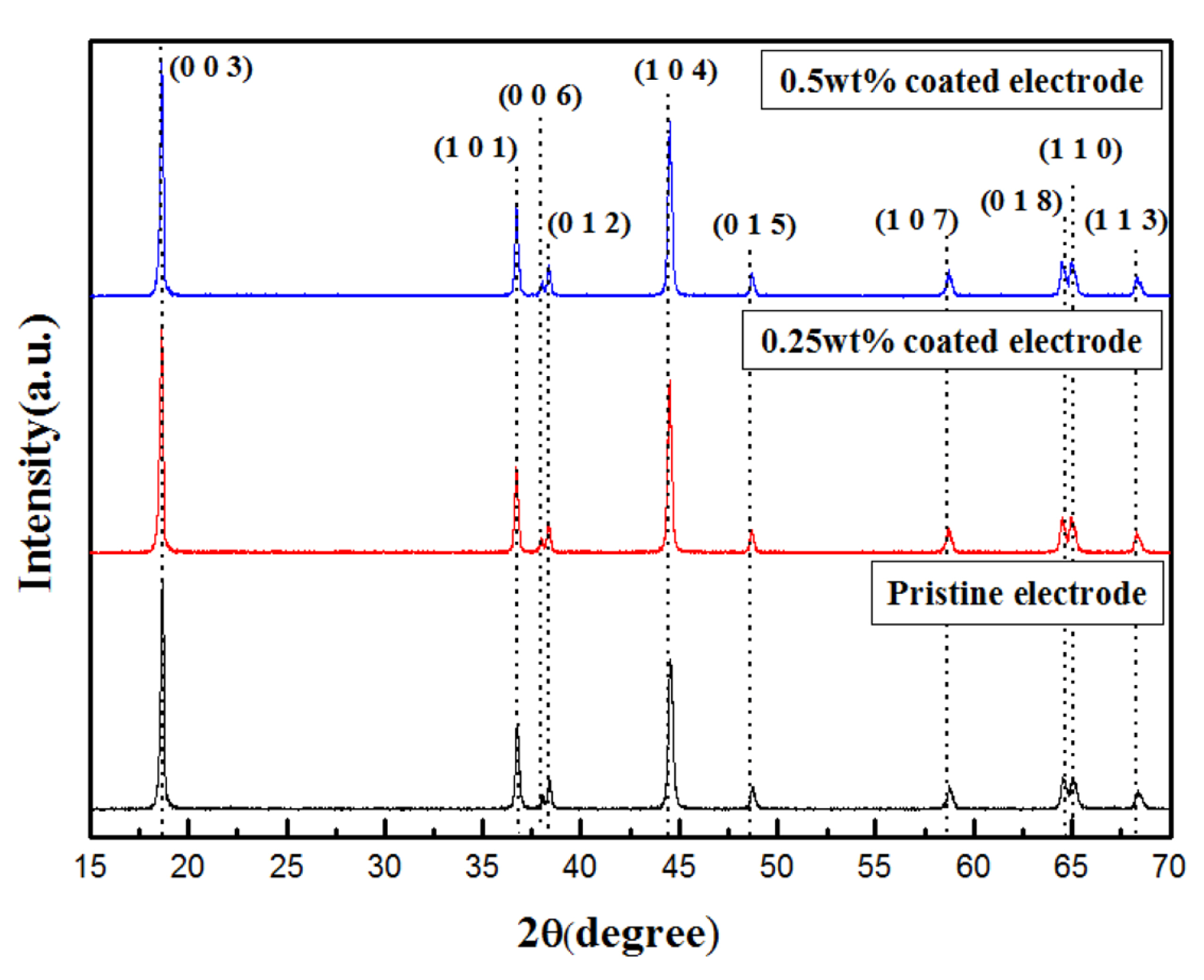
Fig. 1 shows XRD patterns of the pristine and Li
2SiO
3-coated Li[Ni
0.8Co
0.15Al
0.05]O
2 powders. The pristine, 0.25 wt% coated, and 0.5 wt% coated samples showed the same diffraction patterns, and the peaks were well indexed to the typical -NaFeO
2 structure (space group: R-3m). The peaks attributed to Li
2SiO
3 were not detected in the XRD patterns of the coated samples, probably because of the low coating-material content. Clearly, the coating process did not affect the structural integrity of the Li[Ni
0.8Co
0.15Al
0.05]O
2 cathode.
Fig.┬Ā1.
XRD patterns of the pristine, 0.25 wt% Li2SiO3-coated, and 0.5 wt% Li2SiO3-coated Li[Ni0.8Co0.15Al0.05]O2 powders.
To compare the surface morphologies before and after Li
2SiO
3 coating, the pristine and coated Li[Ni
0.8Co
0.15Al
0.05]O
2 powders were observed by SEM, as shown in
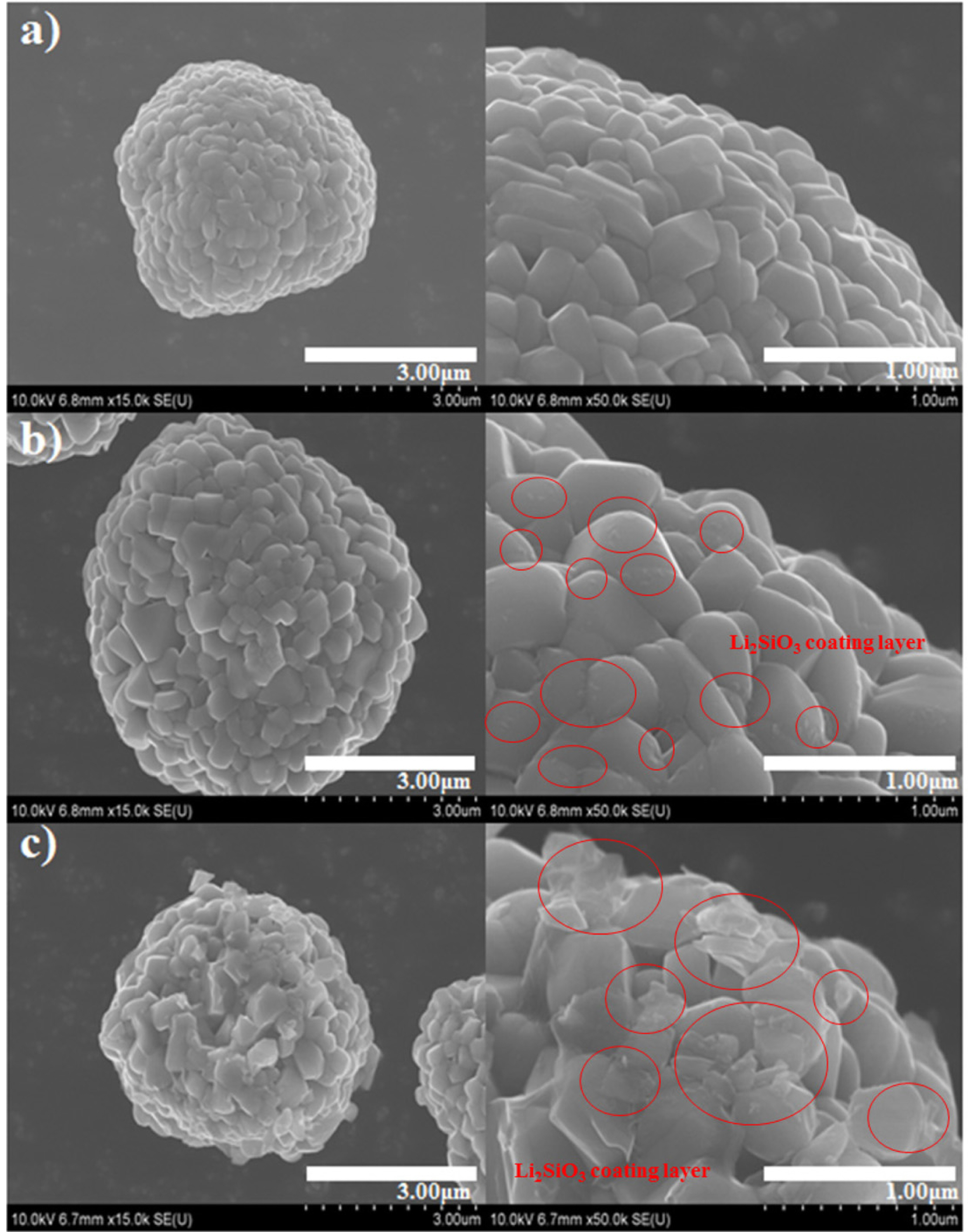
Fig. 2. All three powders consisted of spherical-shaped particles that were composed of nano-sized granules (secondary particles). Whereas the pristine Li[Ni
0.8Co
0.15Al
0.05]O
2 sample showed smooth facets, the surface of the Li
2SiO
3-coated powders was covered with heterogeneous island-type particles (the coating layer is marked with red circles in
Fig. 2), indicating that the Li
2SiO
3 was not distributed on the Li[Ni
0.8Co
0.15Al
0.05]O
2 surface as a film-type coating layer. The 0.5 wt% coated powder was covered with a greater amount of coating material than the 0.25 wt% coated sample. The amount of coating material can affect the electrochemical performance of the electrodes; as Li
2SiO
3 is an electrically non-conductive material, a thick coating layer can hinder the movement of electrons at the cathode/electrolyte interface.
Fig.┬Ā2.
SEM images of (a) pristine, (b) 0.25 wt% Li2SiO3-coated, and (c) 0.5 wt% Li2SiO3-coated Li[Ni0.8Co0.15Al0.05]O2 powders.
Electrochemical measurement of the pristine and Li
2SiO
3-coated Li[Ni
0.8Co
0.15Al
0.05]O
2 electrodes was performed over a 3.0-4.5 V voltage range.
Fig. 3a displays the discharge capacity and rate capability of the electrodes before and after surface modification. The cells were tested at current densities of 40, 100, 200, 600, and 1200 mA┬Ęg
ŌłÆ1 . After an initial fluctuation, the Li
2SiO
3-coated electrodes showed higher capacities than the pristine electrode at all current densities. The relatively higher capacities of the Li
2SiO
3-coated electrodes at high current densities suggest that the rate capability of the coated electrodes was superior compared to the pristine sample.
Fig. 3(b-
d) shows the discharge profiles at 40, 200, and 1200 mA┬Ęg
ŌłÆ1, corresponding to the 5
th, 25
th, and 45
th cycles shown in
Figure 3a, respectively. At 40 mA┬Ęg
ŌłÆ1, the capacities of the pristine, 0.25 wt% coated, and 0.5 wt% coated electrodes were ~191, ~208, and ~200 mAh┬Ęg
ŌłÆ1, respectively. Thus, the difference in capacity among the samples was within 20 mA┬Ęg
ŌłÆ1. At 1200 mA┬Ęg
ŌłÆ1, the 0.25 wt% and 0.5 wt% Li
2SiO
3-coated electrodes showed reduced capacities of ~134 and ~123 mAh┬Ęg
ŌłÆ1, respectively; yet these values were much higher than that of the pristine electrode, which dropped to ~99 mAh┬Ęg
ŌłÆ1.
Table 1 summarizes the discharge capacities and capacity retentions of the pristine and Li
2SiO
3-coated samples. The capacity retention of the pristine electrode at 1200 mA┬Ęg
ŌłÆ1 was ~50% of that measured at a current density of 40 mA┬Ęg
ŌłÆ1, whereas the retention rates of the 0.25 wt% and 0.5 wt% coated electrodes were ~64 and ~61.5%, respectively. The enhanced discharge capacity and rate capability of the coated samples are attributed to the protective coating layer
[28-
35]. During cycling, the cathode surface is usually damaged by the electrolyte; small amounts of moisture in the electrolyte react with the fluoride salt to form HF, which attacks the cathode surface, resulting in the dissolution of transition metals and the formation of an undesired surface layer. The Li
2SiO
3 coating is electrically non-conductive, although it displays considerable ionic conductivity. Thus, a thick Li
2SiO
3 coating layer can hinder the movement of electrons during the charging/discharging process, which may decrease the capacity and rate capability of the coated electrodes. On the other hand, a thin layer or island-type nano-sized particles can reduce the direct contact between the cathode surface and the electrolyte, thus protecting the cathode surface against attack from the HF-containing electrolyte. The good ionic conductivity of Li
2SiO
3 may also facilitate the movement of lithium ions, thus contributing to the superior rate capability of the Li
2SiO
3-coated samples.
Table┬Ā1.
Discharge capacity and capacity retention of pristine and Li2SiO3-coated Li[Ni0.8Co0.15Al0.05]O2 at current densities of 40, 200, and 1200 mA┬ĘgŌłÆ1. The percentages refer to the capacity retention at the 45th cycle compared with that at the 5th cycle.

Impedance spectroscopy measurements confirmed the Li
2SiO
3 coating effect (
Fig. 4). The Nyquist plots for all three electrodes show a semicircle in the mid-and high-frequency regions and a straight line in the low-frequency range. Each semicircle may be composed of two overlapped semicircles, one of which is related to the solid-electrolyte-interface impedance and the other to the charge-transfer resistance
[29,
42]. The diameter of the semicircle for the Li
2SiO
3-coated samples was smaller than that for the pristine electrode. Thus, we infer that the coating layer may influence the charge-transfer resistance as well as the impedance attributed to the solid-electrolyte-interface. Because the semicircle diameter is an indication of the cell impedance, our results clearly show that the Li
2SiO
3 coating reduced the impedance of the electrodes. This is in agreement with the enhanced rate capability of the Li
2SiO
3-coated samples shown in
Fig. 3. In particular, the superior rate capability of the 0.25 wt% coated electrode can be explained by its semicircle size, which is the smallest of the three electrodes.
Fig.┬Ā3.
(a) Discharge capacity of pristine and Li2SiO3-coated Li[Ni0.8Co0.15Al0.05]O2 at current densities of 40, 100, 200, 600, and 1200 mA┬ĘgŌłÆ1, over a 3.0-4.5 V voltage range. Discharge profiles of the electrodes at (b) 40 mA┬ĘgŌłÆ1, (c) 200 mA┬ĘgŌłÆ1, and (d) 1200 mA┬ĘgŌłÆ1.
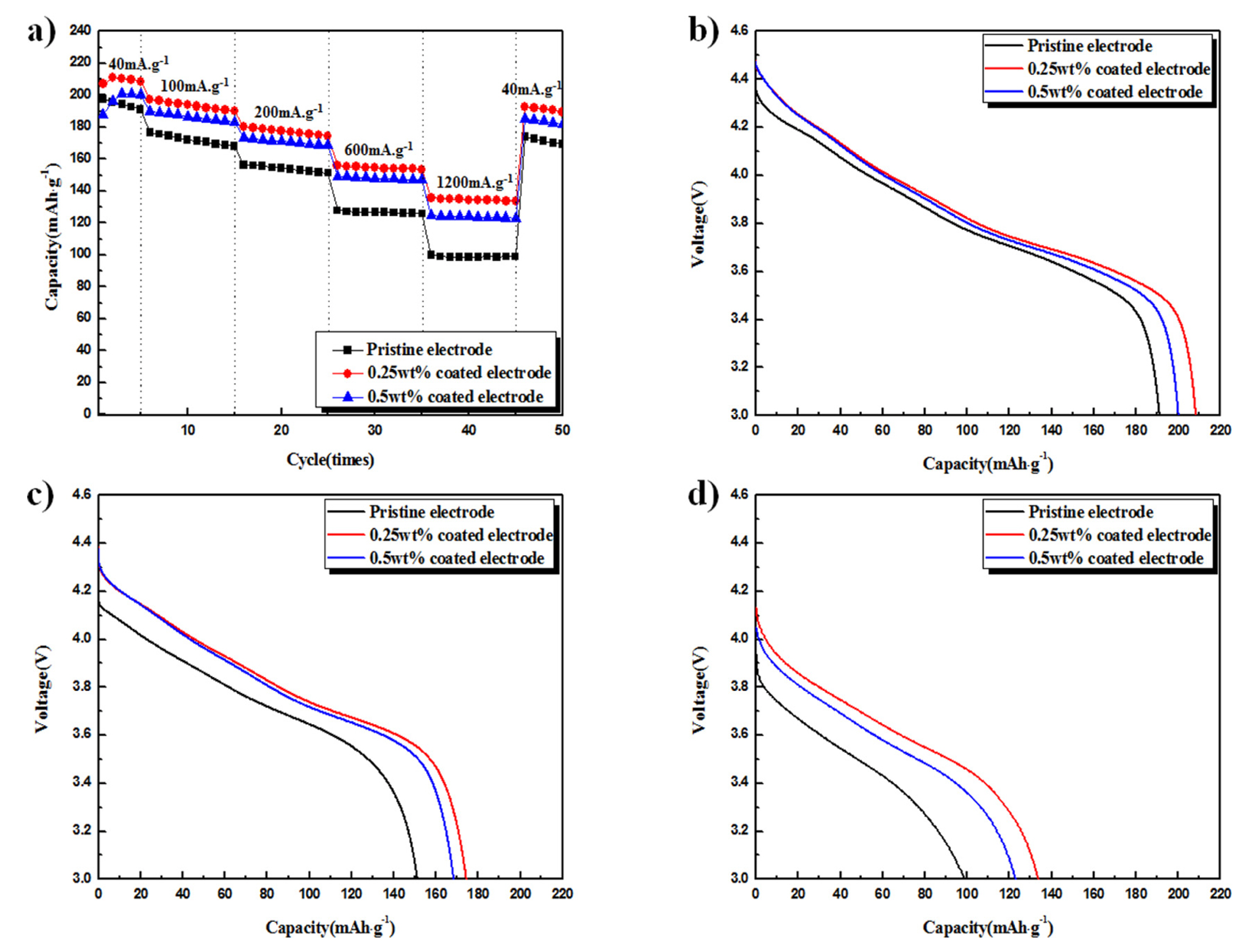
Fig.┬Ā4.
Nyquist plots of the pristine and Li2SiO3-coated Li[Ni0.8Co0.15Al0.05]O2 electrodes.
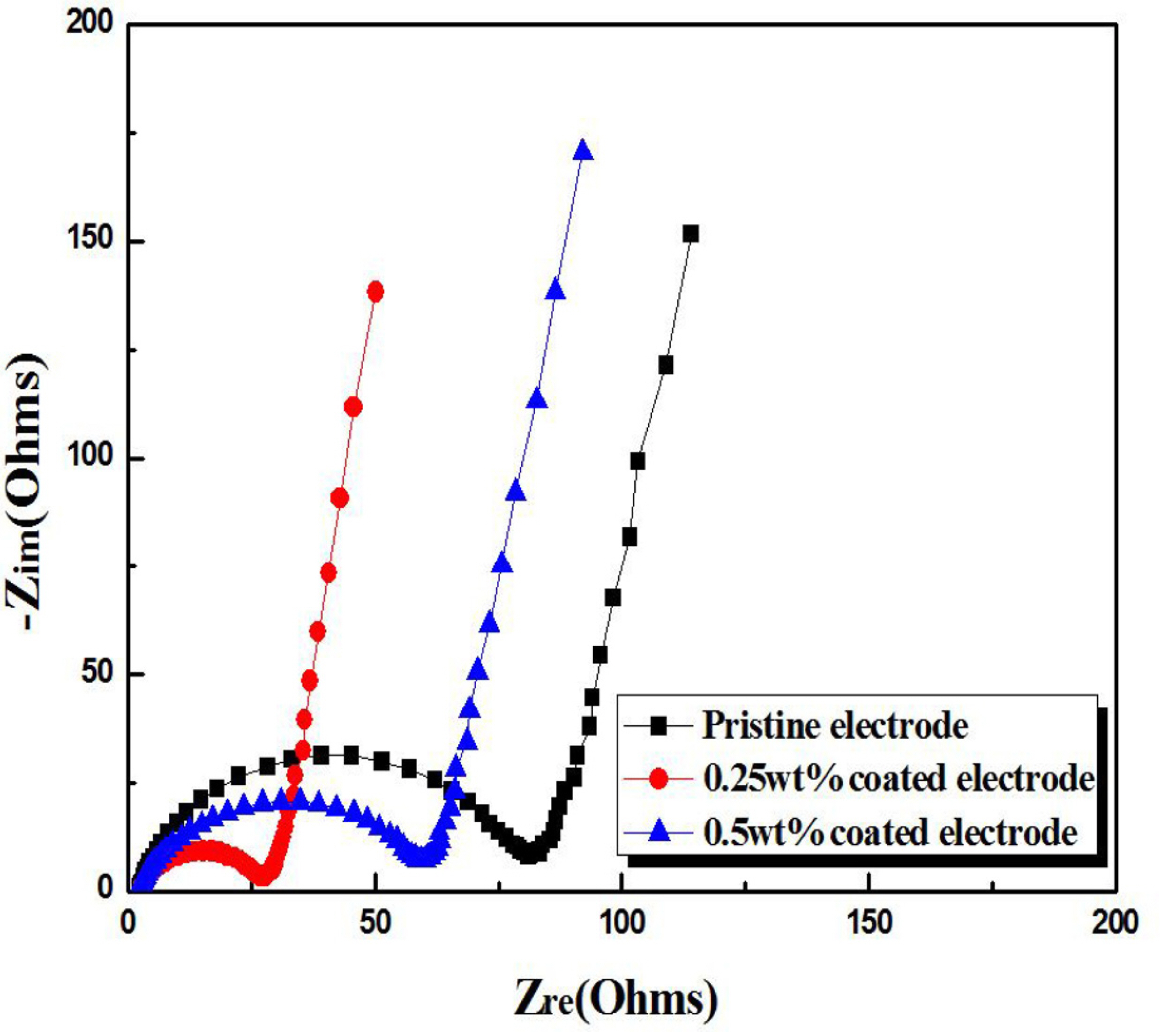
Fig. 5 compares the cycling stability of the pristine and Li
2SiO
3-coated samples at a current density of 100 mA┬Ęg
ŌłÆ1. The capacity of the coated samples was higher than that of the pristine electrode. However, in all cases, the capacity decreased during cycling and surface modification did not result in a clear improvement in the cyclic performance. The Li
2SiO
3 coating did, though, enhance the thermal stability of the charged electrode.
Fig. 6 shows DSC profiles of the fully charged samples. The pristine electrode thermally reacted with the electrolyte at ~170┬░C, and the maximum exothermic peak was observed at ~237┬░C. The exothermic peaks of the Li
2SiO
3-coated samples were clearly shifted to higher temperatures relative to the pristine electrode. In particular, the 0.5 wt% Li
2SiO
3-coated electrode showed the highest maximum exothermic peak temperature (~268┬░C), suggesting that a relatively thick coating layer is effective for improving the thermal stability. As shown in
Fig. 3, the 0.25 wt% Li
2SiO
3 coating enhanced the rate capability of the electrode more than the 0.5 wt% coating, which indicates that a thick coating layer can hinder the movement of electrons. On the other hand, a sufficiently thick surface coating is required to enhance the thermal stability by reducing the contact area between the cathode and the electrolyte and, thus, prevent undesired exothermic reactions at the cathode/electrolyte interface.
Fig.┬Ā5.
Cyclic performances of the pristine and Li2SiO3-coated Li[Ni0.8Co0.15Al0.05]O2 electrodes.
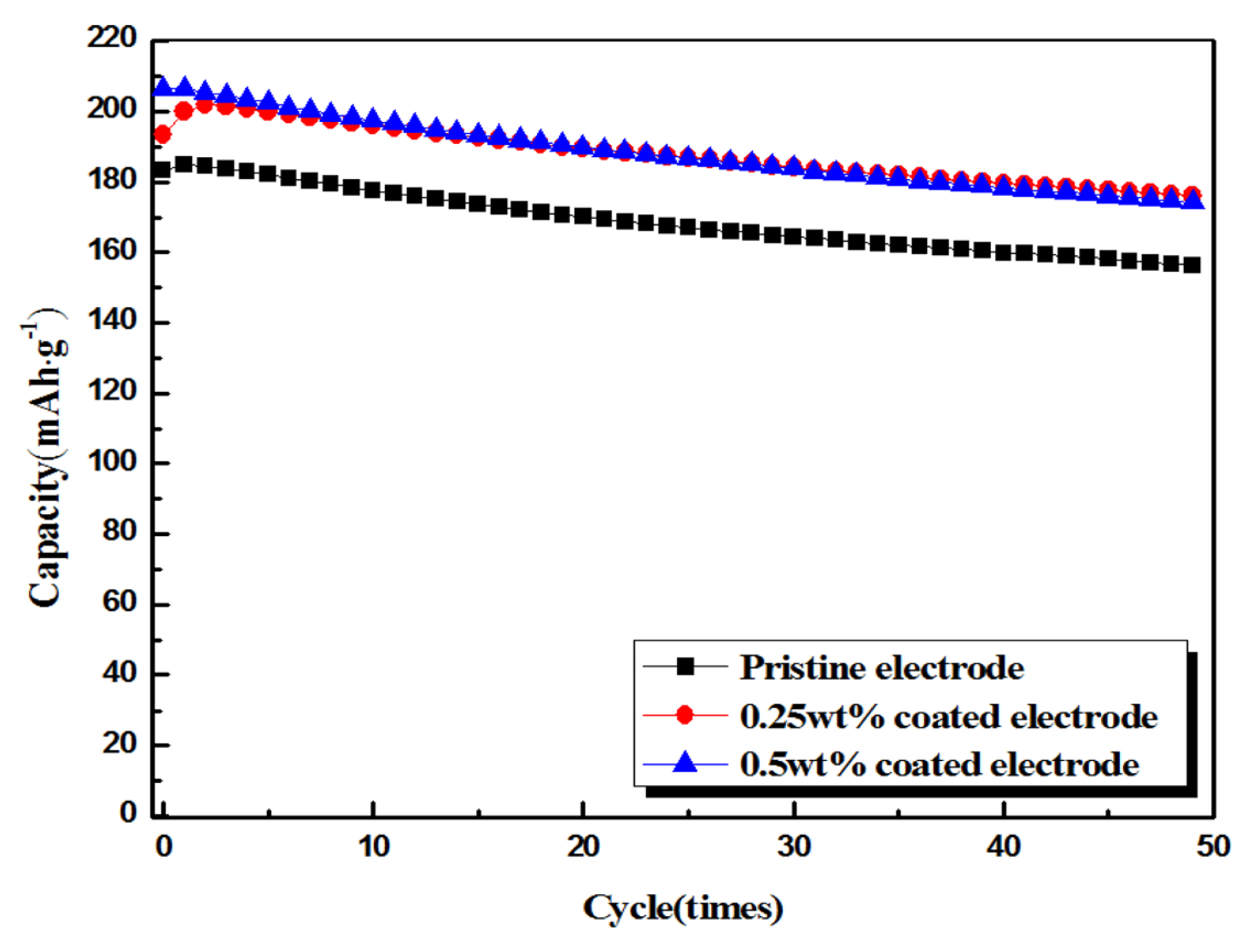
Fig.┬Ā6.
(a) Superimposition of the DSC profiles of the (b) pristine, (c) 0.25 wt% Li2SiO3-coated, and (d) 0.5 wt% Li2SiO3-coated Li[Ni0.8Co0.15Al0.05]O2 electrodes.


