Lithium/Sulfur Secondary Batteries: A Review
Article information
Abstract
Lithium batteries based on elemental sulfur as the cathode-active material capture great attraction due to the high theoretical capacity, easy availability, low cost and non-toxicity of sulfur. Although lithium/sulfur (Li/S) primary cells were known much earlier, the interest in developing Li/S secondary batteries that can deliver high energy and high power was actively pursued since early 1990’s. A lot of technical challenges including the low conductivity of sulfur, dissolution of sulfur-reduction products in the electrolyte leading to their migration away from the cathode, and deposition of solid reaction products on cathode matrix had to be tackled to realize a high and stable performance from rechargeable Li/S cells. This article presents briefly an overview of the studies pertaining to the different aspects of Li/S batteries including those that deal with the sulfur electrode, electrolytes, lithium anode and configuration of the batteries.
1. Introduction
In the pursuit for smaller, lighter, cheaper and non-toxic batteries with high specific energy, lithium/sulfur (Li/S) batteries have gained great attraction. The combination of lithium metal with a theoretical specific capacity of 3830 mAh g−1 as the anode and elemental sulfur (S8) with a theoretical specific capacity of 1675 mAh g−1 as the cathode in a battery can generate a high theoretical specific energy of 2600 Wh kg−1[1]. The energy characteristics of Li/S battery are much superior to those of the known battery systems: lead-acid, nickel/cadmium (Ni/Cd) and nickel/metal hydride (Ni/MH) have specific energies < 300 Wh kg−1, and lithium-ion has < 600 Wh kg−1. Table 1 shows the important properties of sulfur as a positive electrode (cathode) material for lithium secondary batteries in comparison with those of the presently used transition metal oxides and lithium iron phosphate. Although the operational voltage of sulfur is comparatively lower than other cathode materials, it can exhibit the highest theoretical capacity due to the complete reaction with lithium to form Li2S. Sulfur is also the most cost-effective material among the available cathodes. Additionally, the abundance of sulfur in nature and its non-toxic nature make it a very attractive cathode material for low cost and high energy batteries.
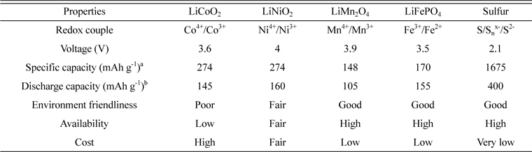
Salient properties of sulfur in comparison with the other cathode active materials of Li-ion batteries
The high capacity and rechargeability of sulfur are achieved from the electrochemical cleavage and reformation of sulfur-sulfur (S-S) bonds in the cathode. The emergence of first Li/S cell is tracked back in 1970’s [2]. However, the development of rechargeable Li/S cells encounters a number of hurdles such as the insulating nature of sulfur, solubility of discharge products in the liquid electrolytes and poor sulfur utilization over repeated cycles. Sulfur in the vapor state was used in some of the early studies as the active material along with molten polysulfides and solid electrolytes [3]. Rechargeable Li/S batteries that could operate at ambient-temperature were not considered practical until Chu in 1990’s designed cells that showed > 50 % sulfur utilization in repeated cycles [4,5]. The renewed efforts undertaken since then to exploit the potential of Li/S redox couple resulted in achieving a substantial progress, and recently the technology has been commercialized by a few industries like Sion Power Corporation [6]. Li/S cell technology has shown a commendable growth profile over the past few years; thus, a specific energy of ~200 Wh kg−1 achieved in 2001 increased to ~350 Wh kg−1 by 2006 and is poised to reach at least 600 Wh kg−1 in the near future.
2. Electrochemical Characteristics of Li/S Batteries
A Li/S cell uses lithium metal as the negative electrode material and elemental sulfur (cyclo-octasulfur, S8, an eight-membered ring form is known to be the most stable) or sulfur-based compounds with S-S bond, as the positive electrode material. During the process of discharging of the cell, lithium metal anode gets oxidized to produce electrons which reach the sulfur cathode through the external circuit. At the cathode, sulfur undergoes electrochemical reduction by accepting the electrons, i.e. the S-S bonds break to produce a series of polysulfides, Snx−, with a decrease in oxidation number of sulfur. The complete reduction of sulfur leads to the formation of Li2S on the cathode. During the process of charging, the above reactions are reversed as schemed in Fig. 1. Lithium gets deposited at the anode while S-S bonds are reformed at the cathode by electrochemical oxidation of Li2S and Snx− with an increase in oxidation number of sulfur. The polysulfides are either linear or cyclic in structure depending on the value of ‘n’ in Snx−. Thus, the chain form is stable for n <5, the cyclic form is stable for n = 8 or 9, and either the cyclic or chain form for n = 6 or 7 [7]. The formation of various polysulfides in different non-aqueous solvents as well as their characteristics have been investigated by researchers using chemical, electrochemical and spectroscopic methods, and different sulfur-reduction mechanisms have been proposed; however, some of them still remain controversial [8]. Such studies revealed unambiguously that the electrochemical reduction of sulfur used as cathode-active material in batteries is very much complicated with the reaction path and final products depending on a number of factors.
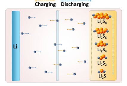
Schematic diagram of Li/S cell electrochemistry.
The electrically non-conductive nature of sulfur (5×10⁻³⁰ S cm−1 at 25 ℃) [9] necessitates its mixing with conductive materials like carbon to impart electrical accessibility when used as the electrode in batteries. An appropriate binder is also added in the cathode formulation to provide integrity for the mixture of sulfur and carbon. A typical cyclic voltammogram (CV) of the sulfur-based cathode at room temperature which reveals the active voltage range is shown in Fig. 2a. A liquid electrolyte of 1 M lithium trifluoromethanesulfonate (LiCF3SO3) in tetra (ethylene glycol) dimethyl ether (TEGDME) solvent is used as the electrolyte in the cell. Two distinct reduction peaks are observed corresponding to the multiple reduction steps: the one at ~2.3 V results from the reduction of sulfur to soluble lithium polysulfides (Li2Sn, 2 < n < 8), and the other at 1.9 V results from the further reduction of polysulfides to solid lithium sulfides Li2S2 and Li2S [10,11]. The single oxidation peak at 2.5 V is attributed to the oxidation of lithium sulfides to polysulfides. The charge-discharge capacity vs. voltage profile of a room temperature Li/S cell is depicted in Fig. 2b. The pattern of discharge curves is typically showing two voltage plateau regions: the higher at ~2.4 V is less predominant compared to the lower at ~2.0 V, which is consistent with the CV profile.
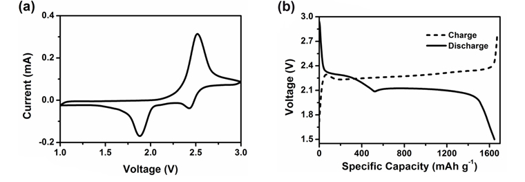
Typical (a) CV curve and (b) charge-discharge capacity vs. voltage profile of a sulfur-based cathode at room temperature.
The mechanism of charge-discharge processes in a room temperature Li/S cell with poly(vinylidene fluoride) (PVdF)-based polymer electrolyte (PE) has been investigated by Ryu et al. using a combination of scanning electron microscopy (SEM), differential scanning calorimetry (DSC) and X-ray diffraction (XRD) [12,13]. Fig. 3a presents the first discharge curve of this cell which generated a high capacity of 1268 mAh g−1 of sulfur, corresponding to 76 % utilization of theoretical capacity. Sulfur electrode samples (a) to (d) shown by arrows in the figure were selected for investigation of the discharge mechanism. It has been concluded that sulfur gets reduced to Li2Sn (n > 4) at the upper plateau region of 2.4 V and these polysulfides get further reduced to Li2S at the lower plateau region of 2.0 V. However, elemental sulfur is not formed again even after full recharge, which leads to the disappearance of the upper plateau during the second discharge with a decrease in capacity to 1028 mAh g−1. Based on the observations, reactions (1) and (2) have been suggested as occurring at the upper and lower voltage regions, respectively; forward reactions during discharge and reverse reactions during charge.


Li2S gets converted back to polysulfides during charging process following the reverse reaction (2); however, formation of sulfur by reverse reaction (1) does not occur. This results in an irreversible loss of active material in the form of polysulfides and Li2S that gets deposited on cathode matrix. The irreversible loss increases with repeated cycling of the cell leading to a fast capacity fade. The authors have proposed a model as shown in Fig. 3b to represent the discharge and charge processes in a Li/S cell, which accounts for the above observations [12].
The structural changes of sulfur cathode during the charge-discharge process of a Li/S cell employing a liquid electrolyte (0.5 M LiCF3SO3 in TEGDME) have been investigated in detail by Cheon et al. using SEM, XRD and wave dispersive spectroscopy (WDS) [14]. The cathode morphology examination at different depths of discharge has shown a significant change in morphology at the end of the lower (2.1 V) plateau. The surface of the carbon matrix is covered with a solid film which was identified to be Li2S and this passivation by Li2S became more severe at 1.5 V. The changes in cathode morphology observed during charging at different depths of charge has indicated that the dense passivation layer of Li2S gets progressively reduced with charging and at 100 % charging there is no apparent layer of Li2S. XRD and WDS data revealed that polysulfides are not getting oxidized to solid sulfur during charging. Several such studies identify the following to be the major factors affecting cycle performance of Li/S cells: the dissolution of polysulfide reduction products in the electrolyte, migration of polysulfides away from cathode causing a decrease in their availability for further reaction, deposition of solid reduction products Li2S2 and Li2S on the cathode conductive matrix, and self-discharge of the polysulfides at lithium anode.
3. Early Studies
A number of early studies deal with the formation, reduction mechanism and solubility of lithium polysulfides, Li2Sn, in different non-aqueous solvents. The solubility was found to vary widely in different solvents as a result of solvent-solute interactions. The requirement for good solubility was identified to be high solvent basicity; whereas, solubility had no significant correlation to dielectric constant (D) [15]. Thus, the best solvents were dimethyl sulfoxide (DMSO) and tetrahydrofuran (THF) with >10 M solubility, N,N-dimethyl acetamide (DMAc) and N,N-dimethyl formamide (DMF); whereas, dimethyl sulfite, methylformate, nitromethane and propylene carbonate (PC) were poor solvents. It was also shown that the favored chain length of polysulfides is related to D, lower D values favor the formation of longer chains. Reduction of sulfur and polysulfides in DMF [16], THF [17] and at a glassy carbon electrode in THF [18,19] were also investigated. Ultraviolet (UV)-visible, electron spin resonance (ESR), Raman spectra, CV and time resolved spectro-electrochemical techniques were adopted for these studies. Different reduction mechanisms have been proposed, with a number of factors influencing the reaction path and products.
Early research in the field of Li/S cells employed liquid electrolytes as the ionic transport media as well as the ionic conductor within the sulfur electrode [20-22]. These electrodes exhibited poor sulfur utilization and/or cycle lives, e.g. only 5 % utilization over 120 cycles [23]; a maximum of 45 % sulfur utilization initially which decreased to 25 % on cycling [24]. The studies with electrolytes containing lithium polysulfides [25,26] and poly(ethylene oxide) (PEO)-based polymer electrolytes [27] also reported poor results. Addition of a Lewis acid like boron trifluoride (BF3) that supposedly suppressed polysulfide formation was found to improve sulfur utilization [28]. Improved performance was reported by employing dissolved sulfur (as Li2Sn in THF) as the cathode (liquid cathode) [25]. However, in this case a penalty is paid in theoretical energy characteristics since sulfur is in the partially reduced state initially itself. The use of a “reacted electrolyte” prepared from lithium powder, carbon disulfide and lithium salt in organic solvent was reported to be effective in boosting discharge efficiency by minimizing the formation of polysulfides on the cathode during redox process [22]. The development of a low-rate, laboratory prototype Li/S cell using lithium perchlorate (LiClO4) in THF/toluene electrolyte was also described [29]. Based on the unassuming earlier results, Li/S systems were deemed suitable only as primary batteries, which is functional at very low current densities. Interest in rechargeable Li/S chemistry was revived following the reports on higher sulfur utilization and better cycle property at room temperature using polymer/gel electrolytes [30].
4. Research Advancing
The research on Li/S cells from year 2000 has been broadly classified here into three main categories for the ease of reviewing according to the components in a battery. They are, studies dealing with (a) sulfur electrode: cathode composition, sulfur composite cathodes and cathode additives, (b) electrolyte in the cell: liquid, gel/polymer and inorganic types, (c) lithium anode: surface protection, and (d) cell configurations of new designs. Some of the studies, of course, belong to more than one category and are referred to in appropriate places.
4.1. Sulfur cathode
Since the sulfur electrode consists of the conductive agent and binder in addition to the active material, it becomes mandatory to optimize the electrode formulation for achieving the desired performance level from a Li/S cell. Higher sulfur content is preferred in terms of a higher specific energy for the cell; whereas, higher carbon content ensures proper electronic contact for electrochemical reactions and higher binder content imparts better structural integrity to the cathode film. A number of factors such as the particle size and proportion of the constituents of cathode, homogeneity of cathode film (which depends on the mixing process), effectiveness of conductive coating on the material and porosity of the cathode have been found to influence sulfur utilization to considerable extents.
4.1.1. Sulfur
Elemental sulfur-based cathode compositions generally contain 40-70 wt.% of sulfur; studies with lower (e.g. 20 %) [31] and higher (e.g. 84 %) [32] sulfur contents are exceptions. A decrease in discharge capacity with an increase in sulfur content has been observed by several researchers [33-35]. For sulfur content variation between 40-80 % in a cathode consisting of elemental sulfur, carbon and PEO in a room temperature Li/S cell with a gel polymer electrolyte, a considerable decrease in discharge capacity has been observed with increase in sulfur content. At higher sulfur loading, carbon content is proportionately reduced resulting in decreased porosity of the cathode and a less effective conductive coating over the particles. Also, sulfur particles tend to agglomerate at higher contents reducing the overall homogeneity of the composition. The larger amount of polysulfides resulting from higher sulfur content might dissolve in the electrolyte and lead to an increase in viscosity of the medium that might cause a decrease in ionic conductivity of the electrolyte [36]. Sulfur particle size is reported to influence the electrochemical performance; smaller particles with higher surface area result in higher sulfur utilization [37,38]. Reduced particle size leads to better uniformity for the electrode and provides better adhesion between electrode and separator; thus, decreasing interfacial resistance and improving battery performance.
4.1.2. Binder and conductive agent
The binders most commonly used in Li/S cells are polymeric materials which may be (a) ionically conducting, like PEO [11,12,33,35,39-41], nafion [42], polyacrylic acid (PAA) [43], (b) electronically conducting, like polyanilines and polypyrroles [44,45], or (c) inert, like poly(tetrafluoro ethylene) (PTFE) [46-48], fluorinated polymers like PVdF and poly(vinylidenefluoride-co-hexafluoro propylene) (PVdF-HFP) [31,44,49-52], polyvinylpyrrolidone (PVP) [53], gelatin [54,55], carboxymethylcellulose (CMC) and styrene-butadiene rubbers [13,56,57]. The binder has to strongly bind the positive active material and conductive agent to the current collector and enhance the mechanical integrity of the electrode. The essential requirements to be met by a binder include: good solubility in the mixing solvent, easy wettability by the electrolyte, ability to form conductive networks between the active material and conductive agent, non-swollen and inactive with polysulfides to maintain the porous structure of sulfur cathode. The organic mixing solvent for cathode preparation has to be carefully chosen based on the binder material such that it has high binder solubility and low sulfur solubility to avoid settling of denser sulfur particles that might form an insulating layer on the current collector. Hwang et al. discloses the most suitable binder-solvent combinations in Li/S cells as: PVdF-DMF, poly(vinyl acetate) (PVAc)-acetonitrile, polyvinylpyrrolidone (PVP)-isopropyl alcohol [53]. In a study with different binders such as PTFE+PVA and PTFE + CMC and PVP of different molecular weights for sulfur cathodes in Li/S cell, it was found that the pore distribution in cathode was nearly independent of the binder type, but pore area was the highest for PTFE-CMC binder, which also gave the lowest interfacial resistance [58]. Water-soluble binders, such as PAA, CMC+SBR, etc. are reported to promote structure stability of sulfur electrodes as high adhesion agents. Moreover, they serve as the strong dispersion agents for uniform distribution of sulfur and ensure a good electrical conductive contact, leading to improved cycle retention [43,56,57].
Carbon powder is usually included in cathode formulation as the conductive agent to overcome the insulating nature of the active material. Particles with high surface area and porosity yield better results since they can provide more electrochemical reaction sites. Choi et al. reported the study with carbon powders of varying specific surface area (65-1500 m2 g−1) and dibutyl phthalate (DBP) absorption number (174-510 mL (100g)−1) [36]. They observed that sulfur utilization depends linearly on DBP absorption number, but is not so strongly affected by the specific surface area. The carbon with higher DBP number has more void space and can absorb more quantity of soluble polysulfides and also accommodate the insoluble Li2S. Thus, it helps to limit the out-diffusion of polysulfides from the cathode and enhance sulfur utilization.
Optimization studies of carbon/binder ratio in the cathode composition have revealed its importance in achieving high performance [33,39]. At a constant sulfur loading of 70 %, C/PEO ratio showed stable cycling property with C/PEO ratio of 20/10 [33]. It was observed in this study that the capacity of the cell corresponding to the lower discharge plateau is more sensitive to the carbon and binder content than the upper discharge plateau; and, with an increase in carbon content, lower plateau capacity enhanced remarkably. The cathode with lower carbon content generally shows a high degradation rate on cycling demonstrating the importance of retaining electrical contact by carbon on repeated cycling of the cell. The study by Cheon et al. reported that sulfur cathode with high binder (PEO) content (18 %) provides the most stable discharge capacity on cycling, attributed to the higher mechanical integrity of the cathode achieved in this case [39].
4.1.3. Cathode preparation
Importance of porosity of the cathode and binder morphology in achieving optimum discharge capacity has been highlighted in a study on cathode preparation by two methods such as mechanical stirring and ball mill mixing [39]. Stirring was reported to result in a more porous cathode with uniform distribution of the binder PEO and better electrochemical performance; whereas, during ball milling a dense, thick film of binder was formed over sulfur particles. Cheon et al. studied sulfur cathode with high (84 %) sulfur content and styrene-butadiene rubber as binder, prepared by mixing in planetary mixer and ball milling methods, and observed that ball milling resulted in improved cycle life of the cell by providing uniform carbon distribution and structural integrity for the cathode [32]. This study also showed that the capacity fading is mainly due to structural failure by physical crack propagation of the cathode structure and subsequent formation of the electrochemically irreversible Li2S layer at cracked surfaces of carbon particles.
The influence of sulfur cathode thickness (varied as 15, 30 and 60 µm) on the discharge capacity of Li/S cell was investigated by Cheon et al. [14]. It was observed that an increase in thickness resulted in a decrease in sulfur utilization at all current rates, as a result of the thicker insulative layer of sulfur. The second discharge region where solid Li2S is formed on the surface of carbon matrix in the cathode was highly sensitive to cathode thickness and discharge rate.
Varying with the traditional cathode preparation method, a binder-free sulfur cathode with higher sulfur loading can facilitate the preparation process of electrodes by encapsulating sulfur into a porous carbon layer and directly using as cathode. A commercial carbon cloth was hot pressed with sulfur and the sulfur cathode with a high sulfur loading of 10 mg was obtained by Elazari et al.. The free standing feature of the synthesized carbon templates with big pore volume for housing large amount of sulfur are of great importance [59]. Other scientists further developed this method with vertically-aligned carbon nanotube (CNT) that prepared via either chemical vapor deposition (CVD) or growing carbon on anodic aluminum oxide (AAO) template. Different sulfur infiltration methods aiming at homogeneous mixing of sulfur and carbon were also examined to improve the cycle performance [60-64].
4.1.4. Sulfur composites
It is considerably challenging but attracting to employ sulfur/carbon (S/C) composites as cathode materials using carbons with nano-adsorption and high electrical conducting characteristics for confining sulfur. It is subjected to an unprecedented development in Li/S batteries recent years involving numerous innovative researches around the globe. Carbon structures such as porous carbons [65-67], graphene [68] or graphene oxide [69], hollow carbons [70], and carbon fibers [71,72] have been applied to be nano-adsorption materials with high levels of electrical conductivity. These carbons commonly have nanosized pores inside and sulfur exists in the pores of the materials. S/C composites in the cathode have been reported to improve cycleability by trapping polysulfides in the cathode and enhancing the electric conductivity of the cathode.
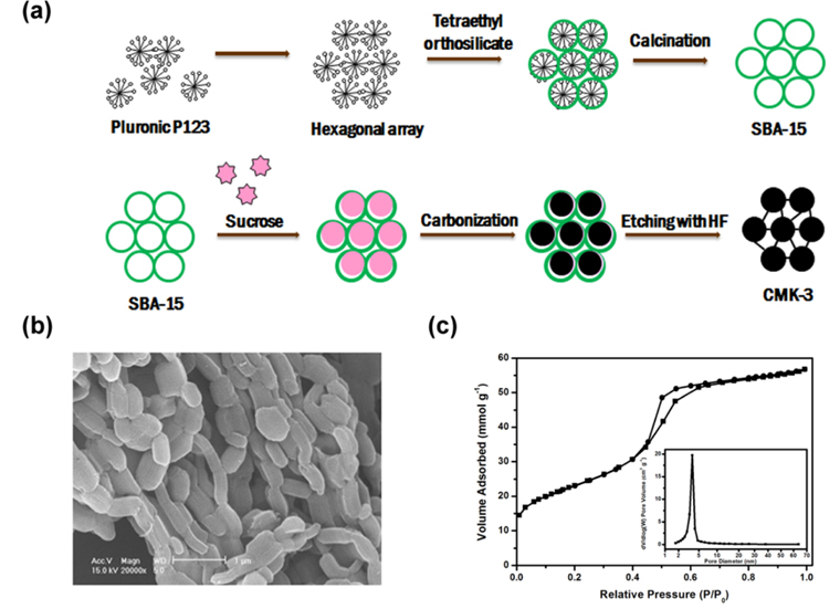
As a “reservoir” for hosting sulfur, carbon materials utilized are required to be highly conductive, and more important, with enough “room” and free space to accommodate sulfur and constrain polysulfides. Various carbons with different morphology, texture, porosity are prepared and studied. When a carbon characterized, its surface area, pore volume and pore size distribution are critically emphasized since these features decide how much sulfur can be confined and how it is distributed. According to the pore size, porous carbons can be classified to be micro- (<2 nm), meso- (2-50 nm), macro- (>50 nm) or combination of them [65,66,73-78]. CMK-3, a typical mesoporous carbon, is prepared from a nanocasting method with SBA-15 as hard template and the preparation process of sulfur/CMK-3 composite is shown in Fig. 4a [79]. CMK-3 displays a fibrous morphology with connected rods in Fig. 4b and its Brunauer-Emmett-Teller (BET) sorption isotherms presented in Fig. 4c exhibit type I and type IV isotherms, which are typical classifications for structures containing micro-size and meso-size pores. A sulfur/CMK composite with a reversible capacity up to 800 mAh g−1 at 0.1 C from Nazar group is worth mentioning and they reported that the mesoporous conductive framework not only constrains sulfur inside of carbon but also facilitates trapping polysulfides formed during the redox, thus enhancing the electrochemical performance of Li/S cells [66]. Zhang et al. encapsulated sulfur into a microporous carbon and they stated the narrow micropores would be the key factor for the enhanced cycle stability and rate capability. To further maximize the sulfur amount that can be embedded in the carbon, Jayaprakash et al. designed a porous hollow carbon with void interior space and a mesoporous shell as a “capsule” for loading sulfur and this carbon sphere facilitated the transport of both lithium ions and electrons. With this S/C composite, outstanding electrochemical performance with extended cycle life and good rate capability [70]. Graphene is a two-dimensional one-atom-thick conductor with good chemical stability, mechanical strength and flexibility and high electric conductivity. Its application in sulfur composite is proved to enhance the electrochemical performance of Li/S cells [68,80-82]. Chen et al. further reported a hierarchical architecture S/MWCNT nanomicrosphere with large pores and they stated the functionalized MWNT can trap polysulfides in the electrode thus achieving higher sulfur utilization and cycle retention [83].
The S/C composite cathode material was generally prepared following a melt-diffusion strategy or a solution method. In a melting-diffusion process, carbon and sulfur are mixed together and heated at 155 ℃ at which temperature sulfur has the lowest viscosity and is beneficial to infuse into the pores of carbon by capillary forces. And some researchers further heat the mixture up to 300 ℃ to evaporate the sulfur residual on carbon surface and impel more sulfur to penetrate deeply in pores by the increased vapor pressure (Fig. 5a) [84]. Infiltration of sulfur solution into porous carbons is another method commonly used in which sulfur is dissolved in some solvents like carbon disulfide (CS2), toluene, oxylene or dimethyl sulfoxide (DMSO) (Fig. 5b) [85,86]. In-situ preparation of sulfur particles under the existence of porous carbons is also tried in many reports by liquid phase precipitation method through reactions of thiosulfate or sulfide with acid (Fig. 5c) [71,87]. Moreover, vaporizing gaseous sulfur to packing the porous hollow carbon was reported to strengthen the sulfur distribution [70].

Sulfur-polyacrylonitrile (PAN) composite prepared by heating a mixture of PAN powder and sublimed sulfur at 300 ℃ has been found to be an attractive active material [88]. The highly polar -CN groups in PAN cyclized to form the thermally stable heterocyclic compound in which sulfur gets intercalated [46]. A study on the influence of synthesis temperature of sulfur-PAN composite has been performed in which it proved the optimum temperature to be 450-500 ℃ [89]. Yin et al. reported a PAN-S/graphene composite with high reversible capacity and good rate capability [90].
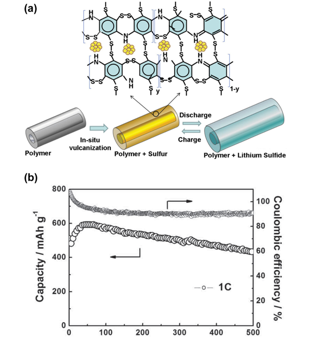
Conducting polymers such as polypyrole (PPy), polythiophene (PTh), Poly(3,4-ethylenedioxythiophene)-poly(styrene sulfonate) (PEDOT:PSS) and polyaniline (PANi) have been successfully used in sulfur composites to improve the cycle performance and the rate capacity of Li/S batteries. The conducting polymers are either used as physical barriers for clogging polysulfides or sulfur absorbents by thermally treatment. Sulfur and polysufides cannot easily escape from the composite with conducting polymer coating. Moreover, the conductive feature of polymers facilitates the lithium ion and electron transport in the Li/S cells and high-rate charge/discharge capability can be expected [44,91-96]. A PANi nanotube/sulfur (SPANI-NT/S) composite was reported in which sulfur reacts with the unsaturated bonds in PANi to form a cross-linked network via a “vulcanization reaction”, providing a strong chemical confinement to the soluble polysulfides (Fig. 6) [97]. PANi can also be used to modify the surface of carbon and it proves that PANi bridges the insulating sulfur and carbon surface, buffers their contact resistance and helps to trap polysulfides, leading to a long cycle life and high coulombic efficiency [98,99].
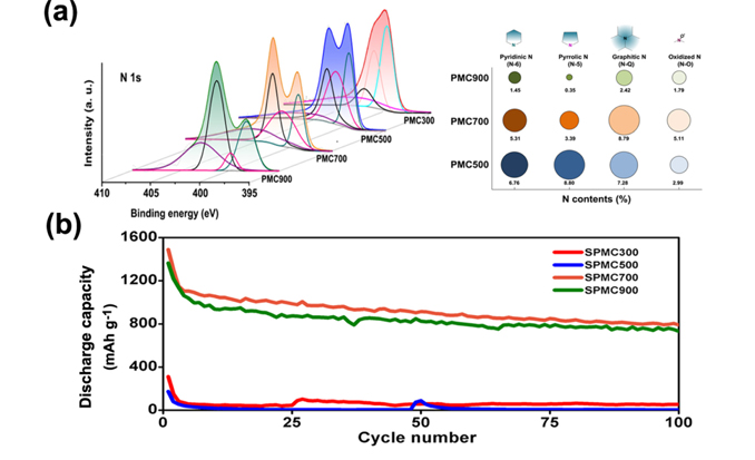
Zheng et al. revealed a new capacity fading mechanism as the detachment of LixS from the surface of carbon during the discharge process [100]. Modifying the carbon surface with heteroatom doping has been proved to efficiently improve the cycle reversibility of Li/S batteries. It was reported that the nitrogen-doped mesoporous carbon promoted the chemical adsorption of sulfur and reached a high areal capacity (3.3 mAh cm2) with high sulfur loading (over 4 mg S cm2) [101]. A highly ordered nitrogen-doped mesoporous carbon has been synthesized with PANi as nitrogen-containing carbon source to provide a top-down strategy of manufacturing high performance S/C composites (Fig. 7) [102]. The highest discharge capacity was delivered with the nitrogen-doped carbon sintered at 700 ℃ due to its maintenance of sufficient functional N species with over 60 % of N-Q and N-O species which contribute to high electric conductivity and high sulfur trapping capacity.
Metal oxides also have been applied to prepare sulfur composite as cathode materials. Wei Seh et al. prepared a yolk-shell structure of titanium oxide (TiO2) / sulfur composite [103]. A core-shell sulfur-TiO2 composite was firstly prepared and a portion of sulfur was then etched away, leaving void space between the sulfur core and TiO2 shell, which can accommodate up to 60 % sulfur volume expansion.
4.2. Electrolytes in Li/S cell
Different types of electrolytes such as liquid, polymer (solid/gel) and glass/ceramic have been studied for their suitability in Li/S cells. The electrolyte should possess the essential requirements of high ionic conductivity, electrochemical stability, chemical stability towards lithium, and safety.
4.2.1. Liquid electrolytes
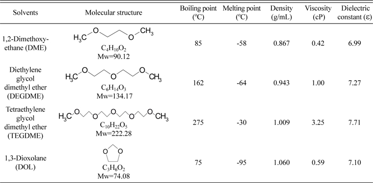
Liquid electrolytes based on solutions of lithium salts such as lithium hexafluorophosphate (LiPF6), lithium perchlorate (LiClO4), LiCF3SO3 and lithium bis(trifluoromethanesulfonyl)imide (LiTFSI) in non-aqueous solvents such as TEGDME, 1,2-dimethoxy-ethane (DME), 1,3-dioxolane (DOL), diglyme (DG), ethylene carbonate (EC)/ dimethyl carbonate (DMC)/ethyl methyl carbonate (EMC), PC/EC, 2-ethoxy-ethyl ether (EEE), triglyme and poly(ethylene glycol) dimethyl ether (PEGDME) have been evaluated in Li/S batteries [48,49,104-107]. The physical properties of commonly used solvents have been listed in Table 2. The solvents have been used either alone or as binary/ternary mixtures. More often, a mixture of solvents was found more suitable than single solvents [48,49,108]. Sulfur-based compounds such as S8, Li2S and polysulfides serve as the active materials during the charge/discharge processes in a Li/S battery, and the electrolyte solvent should dissolve these materials well to avoid irreversible precipitation. Among these compounds, sulfur has a relatively lower polarity; whereas, the sulfide and polysulfides are ionic compounds with higher polarity. Thus, Hwang et al. discloses the selection of a multi-component solvent mixture: first component with a sulfur solubility 20 mM, a second component with sulfur solubility < 20 mM and a third component with a high donor number (D) and a high viscosity [109]. Similarly, a mixture of solvents consisting of one component having a high D with another one having a low viscosity has also been disclosed to result in better properties [110]. Thus, with a properly controlled proportion of the different components of the solvent mixture, high initial capacity and good cycle life are achieved. Ether based solvents have been proved to be the most suitable candidate, among which the binary solvent mixture of DME/DOL with low viscosity has been widely applied [106,111]. DME and DOL operate complementary since DME is more reactive with lithium and provides higher polysulfide solubility while DOL has lower polysulfide solubility but provides a more stable solid electrolyte interface (SEI) on the metallic lithium surface [112].
Physical properties of solvents commonly used in Li/S batteries.
A recent study about electrolyte overturns the traditional knowledge of “salt-in-solvent” with low concentration of lithium salts around 1 M. Suo et al. subjected a new class of non-aqueous liquid ‘solvent-in-salt’ electrolytes. The lithium salt dominates in the lithium ion transport system that the soluble polysulfides are completely restrained in a 7 M electrolyte (Fig. 8a), and the shuttle phenomenon and corrosion of lithium metal in Li/S cells are obviously handled. Consequently, long cycle life with high coulombic efficiency can be achieved (Fig. 8b-c) [113]. Considering the Li/S cell as a liquid electrochemical system, the concentration of soluble polysulfides in the electrolyte plays great role in the cycle performance.

In recent years room temperature ionic liquids (RTILs) are finding increasing applications as battery electrolytes. Thus, a few studies on Li/S cells with RTIL electrolytes have been reported [41,114-118]. The effect of incorporating RTIL based on 1-ethyl-3-methylimidazolium bis(perfluoroethylsulfonyl)imide (EMImTFSI) or 1-butyl-3-methylimidazolium hexafluorophosphate (BMImPF6), as an additive in liquid electrolyte (0.5 M LiCF3SO3 or 0.5 M LiPF6 in DME/DOL solvent) was investigated by Kim et al. [41]. It was found that with 5-10 vol.% of EMImTFSI, the discharge capacity was greatly enhanced to > 600 mAh g−1 after 100 cycles. Employing the RTIL, N-methyl-N-butyl-piperidinium bis(tri-fluoromethanesulfonyl)imide (PP14-TFSI) as the sole electrolyte solvent, improved capacity and cycle performance compared to conventional liquid electrolytes was obtained, which was attributed to the lower polysulfide solubility in RTIL which helps to stabilize the chemical composition and structure of sulfur cathode during charge-discharge processes [119].
4.2.2. Polymer electrolytes
Solid PEs based on PEO,[3,10,120-125] and gel PEs based on PEO [11], PVdF/P(VdF-HFP) [12,34,46,120,126], polyacrylonitrile (PAN) [127], poly (methylmethacrylate) (PMMA) [128], and acrylates/methacrylates [129] have been studied for Li/S cells. Lithium salts such as LiCF3SO3, LiTFSI, LiClO4 and LiPF6 were most often used and the solvents for preparing gel electrolytes were mainly DME/DOL, TEGDME, EC/DMC and PC/EC.
Based on an evaluation of Li/S cell at room temperature, 60 ℃ and 90 ℃ with three different PEs based on PEO, poly(ethylene-methylene oxide) (PEMO) and PEGDME, the limiting factor for ambient temperature cell was identified to be the polarization in PEs; whereas, for 60 ℃ cells it was the incomplete utilization of the sulfur electrode [120]. PEO-based cells gave high initial discharge capacity at 90 ℃, but resulted in a fast capacity fade. PEO-based composite PE with nano-TiO2 and moderate ethylene oxide/Li ratio was found to be more suitable for higher performance at 70 ℃ with conductive sulfur-PAN composite cathode [130]. Hassoun et al. advanced a nano composite solid PE based on PEO-LiCF3SO3 complex containing well dispersed nano-sized zirconia (ZrO2) and Li2S. Li/S cells with this solid PE delivered long-term life and high energy density. Importantly, it evidenced the valid design of all solid state Li/S cells [122]. Gel PEs based on a micro-porous matrix of PVdF/P(VdF-HFP) activated with liquid electrolytes were found to be suited for room temperature performance of Li/S cells [49]. Rao et al. reported Li/S cells combining sulfur-carbon nanofibers and gel PEs based on PAN/PMMA electorspun membranes which advantageously provided an effective conduction path. The cell delivered a capacity retention of 760 mAh g−1 after 50 cycles [127].
4.2.3. Solid-state electrolytes
Solid state Li/S batteries with inorganic solid electrolytes are promising for their high safety compared to organic electrolytes. They are nonflammable, cause no leakage, and do not dissolve the polysulfides that are produced during discharge of sulfur cathode. These electrolytes have the great advantage of possessing lithium ion transport number of unity [131]. Amorphous 60Li2S·40SiS2 (mol%) [132] and 80Li2S·20P2S5 [131,133] are the examples of inorganic electrolytes evaluated in Li/S cells. Nagao et al. prepared a sulfur composited that sulfur, carbon black and 80Li2S·20P2S5 inorganic electrolyte were ball milled together to increase the intimate contact of electrode components, leading to the increase in cell capacity [133].
4.3 Lithium anode
Due to the multistage process in Li/S cells that various polysulfide intermediates are generated, the lithium anode suffers complicated corrosion from the decomposition of solid Li2S2/Li2S which hinders the further transport of active lithium. Besides, polysulfides migrate across the separator and generate side reactions on lithium anode as illustrated in Eq. 3, resulting in limited cycle life and low coulombic efficiency of Li/S cells [112].

Lithium metal protection by a layer of UV-cured polymer, poly(ethylene glycol) dimethacrylate, was reported to enhance cycle performance due to the formation of stable SEI films [134]. The study on self-discharge of Li/S cell with storage time using stainless-steel (SS) current collectors showed severe self-discharge as reported by Ryu et al. [51]. The open circuit voltage (OCV) fell abruptly after 7 days and the discharge capacity reduced to 72 % of its original value after 30. The observation was linked to the corrosion of SS current collector, which was not compatible with sulfur electrode. Self-discharge could be decreased by using corrosion resistant, gold-coated current collector. Cycle life are reported to be elongated by using porous current collector which inhibits the detachment of active material [135].
The modification of liquid electrolyte components or utilization of electrolyte additives can contribute to the lithium anode protection by forming stable SEI films. Solvents like DOL are reported to form passivating surface films on lithium with a series of ROLi species, oligomers with -OLi edge groups. Additives like LiNO3, LiBOB, phosphorous pentasulfide (P2S5), and polysufides are used in electrolyte to protect lithium anode [136-139]. Aurbach et al. proposed the addition of LiNO3 for lithium protection owing to the stable SEI film formed on the Li surface days as illustrated in Fig. 9 [140]. The surface film homogeneously coated on lithium was observed by Xiong et al. via SEM, EIS, and XPS spectra [141]. P2S5 promoted the dissolution of Li2S and formed a passivation layer with major component of Li3PS4 on lithium surface which alleviated capacity loss and inhibited polysulfide shuttling [142]. Another attractive study is the utilization of the polysulfides as both additive in electrolyte and active material in the cathode. Xu et al. reported that the polysulfides addressed an equilibrium between dissolution and precipitation of Li2Sn at the sulfur/electrolyte interface by which the Li/S cells can “self-heal”, and no doubt the needed amount of lithium salt in electrolyte is reduced [139].
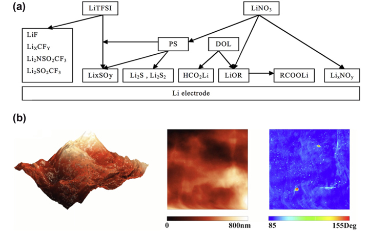
(a) A schematic presentation of the contribution of the various components in DOL/LiTFSI/Li2S6/LiNO3 solutions to the surface chemistry of Li electrodes. (b) Scanning probe microscopy (SPM) images of lithium metal surface immersed in 0.5 M LiNO3/DIOX/DME (1:1, v/v) for 5 h. From left to right column: height (3D) images, height (2D) images and phase images. Reproduced from ref [140,141].
4.4 Li/S cell configurations
Zhang et al. have performed a proof-of-concept Li/S cell that a separated porous sulfur film made from phase inversion method as active material and a carbon layer as cathode current collector. This cell reveals not only the applicability of this architecture but also a query to the importance of initially homogeneous mixing of sulfur and carbon in the cathodes [143]. Likewise, the concepts of inserting a MWNT paper or microporous or fibrous carbon paper between the sulfur cathode and separator contributed analogously to the preparation of sulfur cathodes [144-146].
Safety concerns of lithium sulfur batteries caused by lithium metal are unavoidable issues when involving the practical application. Finding alternatives for the lithium metal has obviously been the other effective approach. Several studies have shown high superiority of Li-free cells with Li2S as cathode material and tin (Sn) or silicon (Si) as anode material [147-150]. In contrast to the traditional Li/S chemistry that cells assembled in the “charged” state, Li2S need to be firstly oxidized to sulfur or high ordered polysulfides, and lithium ions are then reduced to Li-Sn or Li-Si alloy on the anode. The feasibility of this concept was demonstrated by Hassoun et al. who developed Sn/C /GPE/ Li2S/C polymer battery with a Sn/C anode, a PEO-based gel polymer electrolyte, and a Li2S/C cathode. The charge-discharge capacity vs. voltage profile showed typical two plateaus of Li/S cells following an electrochemical process of reversible reaction between Li-Sn alloy and sulfur to form Sn metal and Li2S [151].
The redox reactions in Li/S cells are carried out between the soluble polysulfides and lithium sulfide after the first cycle since sulfur is reduced to polysulfides in the voltage range lower than 3 V, hence it is reasonable to call Li/S cells as “simi-liquid batteries”. Based on this definition, the concept of applying polysulfides directly as active materials, namely, “catholyte”, is raised and investigated by many researchers. Zhang et al. proposed a Li/Li2S9 cell and it showed improved capacity [152]. But they also noticed the cell cannot be charged above 2.5 V due to severe redox shuttle. Another interesting result was performed by Yang et al. in which the catholyte is only cycled between sulfur and Li2S4 by setting the cut-off voltage for discharging to be 2.15 V as a half-flow-mode battery. An energy density of 108 Wh L−1 with cycle life over 2000 cycles have been achieved [153].
5. Summary and Perspectives
Li/S battery technology has evolved over the years through an initial phase as a primary battery and the latter phase as a secondary battery. The initial problems of low sulfur utilization and poor cycle performance, especially at ambient temperatures, have been tackled to a considerable extent. The extensive researches carried out so far including the optimization of sulfur electrode compositions, streamlining of different electrolytes, protection or replacement of lithium anode, and modification of Li/S design have contributed substantially in developing the technology. Porous carbons, polymers or metal oxides for confining sulfur not only act as electronic conductors but also as a nanoscale-dimension chamber where the electrochemical reaction occurred. This concept of sulfur composite was widely verified and dramatically developed by researches around the globe in the recent years, but the critical problem of low sulfur content in the composite still remains as a challenge to the material manufacture and much effort is still on the way.
The energy density and cycle life of Li/S cell has been enhanced dramatically during the past 5-6 years and recently a few industrial firms have commercialized Li/S cells with a specific energy > 350 Wh kg−1. Since Li/S batteries have the potential for application in hybrid and pure electric vehicles, umpteen research activities are still pursued to enhance the performance levels and increase the energy density. Lots of efforts are undertaken in institutions as well as industries to develop and establish the Li/S technology to meet the varied application demands. With the capability of providing more power density than its competitors, Li/S battery is poised to be the most commendable achievement in battery technology in the immediate future.
Acknowledgements
This research was supported by Basic Science Research Program through the National Research Foundation of Korea (NRF) funded by the Ministry of Science, ICT and future Planning (No. NRF-2016 R1A2A2A07005334; No. 2013R1A2A1A01015911).
References
G. A. Nazri and G. Pistoia, Lithium batteries: Science and Technology, Kluwer Academic Publishers, New York, (2004).
Nazri G. A., Pistoia G.. Lithium batteries: Science and Technology Kluwer Academic Publishers. New York: (2004).E. J. Cairns, E. C. Gay, R. K. Steunenberg, H. Shimotake, J. R. Selman, T. L. Wilson and D. S. Webster, in Argonne National Lab: Chicago, Argonne National Lab, Chicago, (1972).
Cairns E. J., Gay E. C., Steunenberg R. K., Shimotake H., Selman J. R., Wilson T. L., Webster D. S.. Argonne National Lab: Chicago Argonne National Lab. Chicago: (1972).R. P. Tischer, The Sulfur electrode: Fused salts and solid electrolytes, Academic Press, New York, (1983).
Tischer R. P.. The Sulfur electrode: Fused salts and solid electrolytes Academic Press. New York: (1983).M. Y. Chu, in US Patent, 5,582,623 (1996).
Chu M. Y.. US Patent (1996). 5,582,623.M. Y. Chu, in US Patent, 5, 523,179 (1996).
Chu M. Y.. US Patent (1996). 5, 523,179.D. H. Han, B. S. Kim, S. J. Choi, Y. Jung, J. Kwak and S. M. Park, J. Electrochem. Soc., 2004, 151, E283-E290.
Han D. H., Kim B. S., Choi S. J., Jung Y., Kwak J., Park S. M.. J. Electrochem. Soc. 2004;151:E283–E290. 10.1149/1.1773733.Y. V. Mikhaylik and J. R. Akridge, J. Electrochem. Soc., 2004, 151, A1969-A1976.
Mikhaylik Y. V., Akridge J. R.. J. Electrochem. Soc. 2004;151:A1969–A1976. 10.1149/1.1806394.J. A. Dean, Lange’s Handbook of Chemistry, McGraw-Hill, New York, (1985).
Dean J. A.. Lange’s Handbook of Chemistry McGraw-Hill. New York: (1985).X. Zhu, Z. Wen, Z. Gu and Z. Lin, J. Power Sources, 2005, 139, 269-273.
Zhu X., Wen Z., Gu Z., Lin Z.. J. Power Sources 2005;139:269–273. 10.1016/j.jpowsour.2004.07.002.B. H. Jeon, J. H. Yeon, K. M. Kim and I. J. Chung, J. Power Sources, 2002, 109, 89-97.
Jeon B. H., Yeon J. H., Kim K. M., Chung I. J.. J. Power Sources 2002;109:89–97. 10.1016/S0378-7753(02)00050-2.H. S. Ryu, H. J. Ahn, K. W. Kim, J. H. Ahn and J. Y. Lee, J. Power Sources, 2006, 153, 360-364.
Ryu H. S., Ahn H. J., Kim K. W., Ahn J. H., Lee J. Y.. J. Power Sources 2006;153:360–364. 10.1016/j.jpowsour.2005.05.037.H. S. Ryu, Z. Guo, H. J. Ahn, G. B. Cho and H. Liu, J. Power Sources, 2009, 189, 1179-1183.
Ryu H. S., Guo Z., Ahn H. J., Cho G. B., Liu H.. J. Power Sources 2009;189:1179–1183. 10.1016/j.jpowsour.2008.12.073.S. E. Cheon, K. S. Ko, J. H. Cho, S. W. Kim, E. Y. Chin and H. T. Kim, J. Electrochem. Soc., 2003, 150, A796-A799.
Cheon S. E., Ko K. S., Cho J. H., Kim S. W., Chin E. Y., Kim H. T.. J. Electrochem. Soc. 2003;150:A796–A799. 10.1149/1.1571532.R. D. Rauh, F. S. Shuker, J. M. Marston and S. B. Brummer, J. Inorg. Nucl. Chem., 1977, 39, 1761-1766.
Rauh R. D., Shuker F. S., Marston J. M., Brummer S. B.. J. Inorg. Nucl. Chem. 1977;39:1761–1766. 10.1016/0022-1902(77)80198-X.F. Gaillard, E. Levillain, M. C. Dhamelincourt, P. Dhamelincourt and J. P. Lelieur, J. Raman Spectrosc., 1997, 28, 511-517.
Gaillard F., Levillain E., Dhamelincourt M. C., Dhamelincourt P., Lelieur J. P.. J. Raman Spectrosc. 1997;28:511–517. 10.1002/(SICI)1097-4555(199707)28:7<511::AID-JRS119>3.0.CO;2-4.S. I. Tobishima, H. Yamamoto and M. Matsuda, Electrochim. Acta, 1997, 42, 1019-1029.
Tobishima S. I., Yamamoto H., Matsuda M.. Electrochim. Acta 1997;42:1019–1029. 10.1016/S0013-4686(96)00281-2.H. Yamin, J. Penciner, A. Gorenshtain, M. Elam and E. Peled, J. Power Sources, 1985, 14, 129-134.
Yamin H., Penciner J., Gorenshtain A., Elam M., Peled E.. J. Power Sources 1985;14:129–134. 10.1016/0378-7753(85)88022-8.H. Yamin, A. Gorenshtein, J. Penciner, Y. Sternberg and E. Peled, J. Electrochem. Soc., 1988, 135, 1045-1048.
Yamin H., Gorenshtein A., Penciner J., Sternberg Y., Peled E.. J. Electrochem. Soc. 1988;135:1045–1048. 10.1149/1.2095868.M. L. B. Rao, in US Patent, 3,413,154 (1968).
Rao M. L. B.. US Patent (1968). 3,413,154.J. R. Coleman and M. W. Bates, Power Sources, Pergamon Press, New York, (1968).
Coleman J. R., Bates M. W.. Power Sources Pergamon Press. New York: (1968).D. A. Nole and V. Moss, in US Patent, 3,532,543 (1970).
Nole D. A., Moss V.. US Patent (1970). 3,532,543.R. D. Rauh, G. F. Pearson and S. B. Brummer, in Proceedings of 12th IECEC Conference, 1977, 1, 283.
Rauh R. D., Pearson G. F., Brummer S. B.. In : Proceedings of 12th IECEC Conference; 1977. 1p. 283.E. Peled, A. Gorenshtein, M. Segal and Y. Sternberg, J. Power Sources, 1989, 26, 269-271.
Peled E., Gorenshtein A., Segal M., Sternberg Y.. J. Power Sources 1989;26:269–271. 10.1016/0378-7753(89)80133-8.R. D. Rauh, K. M. Abraham, G. F. Pearson, J. K. Surprenant and S. B. Brummer, J. Electrochem. Soc., 1979, 126, 523-527.
Rauh R. D., Abraham K. M., Pearson G. F., Surprenant J. K., Brummer S. B.. J. Electrochem. Soc. 1979;126:523–527. 10.1149/1.2129079.E. Peled, Y. Sternberg, A. Gorenshtein and Y. Lavi, J. Electrochem. Soc., 1989, 136, 1621-1625.
Peled E., Sternberg Y., Gorenshtein A., Lavi Y.. J. Electrochem. Soc. 1989;136:1621–1625. 10.1149/1.2096981.P. DeGott, in doctoral thesis, at I’Institut National Polytechnique de Grenoble, France, I’Institut National Polytechnique de Grenoble, France, 1986.
DeGott P.. doctoral thesis, at I’Institut National Polytechnique de Grenoble, France I’Institut National Polytechnique de Grenoble; France: 1986.G. Eichinger and H. P. Fritz, J. Electroanal. Chem. Interfacial Electrochem., 1975, 58, 369-374.
Eichinger G., Fritz H. P.. J. Electroanal. Chem. Interfacial Electrochem. 1975;58:369–374. 10.1016/S0022-0728(75)80094-5.H. Yamin and E. Peled, J. Power Sources, 1983, 9, 281-287.
Yamin H., Peled E.. J. Power Sources 1983;9:281–287. 10.1016/0378-7753(83)87029-3.M. Y. Chu, in US Patent, 5,523,179 (1998).
Chu M. Y.. US Patent (1998). 5,523,179.M. S. Song, S. C. Han, H. S. Kim, J. H. Kim, K. T. Kim, Y. M. Kang, H. J. Ahn, S. X. Dou and J. Y. Lee, J. Electrochem. Soc., 2004, 151, A791-A795.
Song M. S., Han S. C., Kim H. S., Kim J. H., Kim K. T., Kang Y. M., Ahn H. J., Dou S. X., Lee J. Y.. J. Electrochem. Soc. 2004;151:A791–A795. 10.1149/1.1710895.S. E. Cheon, S. S. Choi, J. S. Han, Y. S. Choi, B. H. Jung and H. S. Lim, J. Electrochem. Soc., 2004, 151, A2067-A2073.
Cheon S. E., Choi S. S., Han J. S., Choi Y. S., Jung B. H., Lim H. S.. J. Electrochem. Soc. 2004;151:A2067–A2073. 10.1149/1.1815153.J. Shim, K. A. Striebel and E. J. Cairns, J. Electrochem. Soc., 2002, 149, A1321-A1325.
Shim J., Striebel K. A., Cairns E. J.. J. Electrochem. Soc. 2002;149:A1321–A1325. 10.1149/1.1503076.J. Wang, L. Liu, Z. Ling, J. Yang, C. Wan and C. Jiang, Electrochim. Acta, 2003, 48, 1861-1867.
Wang J., Liu L., Ling Z., Yang J., Wan C., Jiang C.. Electrochim. Acta 2003;48:1861–1867. 10.1016/S0013-4686(03)00258-5.H. S. Ryu, J. W. Choi, J. H. Ahn, G. B. Cho and H. J. Ahn, Mater. Sci. Forum, 2006, 510-511, 50-53.
Ryu H. S., Choi J. W., Ahn J. H., Cho G. B., Ahn H. J.. Mater. Sci. Forum 2006;510-511:50–53. 10.4028/www.scientific.net/MSF.510-511.50.D. R. Chang, S. H. Lee, S. W. Kim and H. T. Kim, J. Power Sources, 2002, 112, 452-460.
Chang D. R., Lee S. H., Kim S. W., Kim H. T.. J. Power Sources 2002;112:452–460. 10.1016/S0378-7753(02)00418-4.Y. S. Choi, S. Kim, S. S. Choi, J. S. Han, J. D. Kim, S. E. Jeon and B. H. Jung, Electrochim. Acta, 2004, 50, 833-835.
Choi Y. S., Kim S., Choi S. S., Han J. S., Kim J. D., Jeon S. E., Jung B. H.. Electrochim. Acta 2004;50:833–835. 10.1016/j.electacta.2004.05.048.D. C. Hwang, in US Patent, 20040091776 A1.
Hwang D. C.. US Patent 20040091776 A1.S. E. Cheon, J. H. Cho, K. S. Ko, C. W. Kwon, D. R. Chang, H. T. Kim and S. W. Kim, J. Electrochem. Soc., 2002, 149, A1437-A1441.
Cheon S. E., Cho J. H., Ko K. S., Kwon C. W., Chang D. R., Kim H. T., Kim S. W.. J. Electrochem. Soc. 2002;149:A1437–A1441. 10.1149/1.1511187.S. Kim, Y. Jung and H. S. Lim, Electrochim. Acta, 2004, 50, 889-892.
Kim S., Jung Y., Lim H. S.. Electrochim. Acta 2004;50:889–892. 10.1016/j.electacta.2004.01.093.S. Kim, Y. Jung and S. J. Park, J. Power Sources, 2005, 152, 272-277.
Kim S., Jung Y., Park S. J.. J. Power Sources 2005;152:272–277. 10.1016/j.jpowsour.2005.03.003.H. Schneider, A. Garsuch, A. Panchenko, O. Gronwald, N. Janssen and P. Novák, J. Power Sources, 2012, 205, 420-425.
Schneider H., Garsuch A., Panchenko A., Gronwald O., Janssen N., Novák P.. J. Power Sources 2012;205:420–425. 10.1016/j.jpowsour.2011.12.061.Z. Zhang, W. Bao, H. Lu, M. Jia, K. Xie, Y. Lai and J. Li, ECS Electrochem. Lett., 2012, 1, A34-A37.
Zhang Z., Bao W., Lu H., Jia M., Xie K., Lai Y., Li J.. ECS Electrochem. Lett. 2012;1:A34–A37. 10.1149/2.009202eel.J. Wang, J. Chen, K. Konstantinov, L. Zhao, S. H. Ng, G. X. Wang, Z. P. Guo and H. K. Liu, Electrochim. Acta, 2006, 51, 4634-4638.
Wang J., Chen J., Konstantinov K., Zhao L., Ng S. H., Wang G. X., Guo Z. P., Liu H. K.. Electrochim. Acta 2006;51:4634–4638. 10.1016/j.electacta.2005.12.046.M. Sun, S. Zhang, T. Jiang, L. Zhang and J. Yu, Electrochem. Commun., 2008, 10, 1819-1822.
Sun M., Zhang S., Jiang T., Zhang L., Yu J.. Electrochem. Commun. 2008;10:1819–1822. 10.1016/j.elecom.2008.09.012.J. Wang, J. Yang, J. Xie and N. Xu, Adv. Mater., 2002, 14, 963-965.
Wang J., Yang J., Xie J., Xu N.. Adv. Mater. 2002;14:963–965. 10.1002/1521-4095(20020705)14:13/14<963::AID-ADMA963>3.0.CO;2-P.J. Wang, Y. Wang, X. He, J. Ren, C. Jiang and C. Wan, J. Power Sources, 2004, 138, 271-273.
Wang J., Wang Y., He X., Ren J., Jiang C., Wan C.. J. Power Sources 2004;138:271–273. 10.1016/j.jpowsour.2004.06.032.B. Jin, J. U. Kim and H. B. Gu, J. Power Sources, 2003, 117, 148-152.
Jin B., Kim J. U., Gu H. B.. J. Power Sources 2003;117:148–152. 10.1016/S0378-7753(03)00113-7.J. W. Choi, J. K. Kim, G. Cheruvally, J. H. Ahn, H. J. Ahn and K. W. Kim, Electrochim. Acta, 2007, 52, 2075-2082.
Choi J. W., Kim J. K., Cheruvally G., Ahn J. H., Ahn H. J., Kim K. W.. Electrochim. Acta 2007;52:2075–2082. 10.1016/j.electacta.2006.08.016.W. Zheng, Y. W. Liu, X. G. Hu and C. F. Zhang, Electrochim. Acta, 2006, 51, 1330-1335.
Zheng W., Liu Y. W., Hu X. G., Zhang C. F.. Electrochim. Acta 2006;51:1330–1335. 10.1016/j.electacta.2005.06.021.H. S. Ryu, H. J. Ahn, K. W. Kim, J. H. Ahn, J. Y. Lee and E. J. Cairns, J. Power Sources, 2005, 140, 365-369.
Ryu H. S., Ahn H. J., Kim K. W., Ahn J. H., Lee J. Y., Cairns E. J.. J. Power Sources 2005;140:365–369. 10.1016/j.jpowsour.2004.08.039.H. S. Ryu, H. J. Ahn, K. W. Kim, J. H. Ahn, K. K. Cho, T. H. Nam, J. U. Kim and G. B. Cho, J. Power Sources, 2006, 163, 201-206.
Ryu H. S., Ahn H. J., Kim K. W., Ahn J. H., Cho K. K., Nam T. H., Kim J. U., Cho G. B.. J. Power Sources 2006;163:201–206. 10.1016/j.jpowsour.2005.12.061.D. Hwang, Y. S. Choi, S. Choi, J. Lee, Y. Jung, J. Kim and Z. Park, in US Patent, 0,039,680 A1 (2002).
Hwang D., Choi Y. S., Choi S., Lee J., Jung Y., Kim J., Park Z.. US Patent (2002). 0,039,680 A1.J. Sun, Y. Huang, W. Wang, Z. Yu, A. Wang and K. Yuan, Electrochim. Acta, 2008, 53, 7084-7088.
Sun J., Huang Y., Wang W., Yu Z., Wang A., Yuan K.. Electrochim. Acta 2008;53:7084–7088. 10.1016/j.electacta.2008.05.022.Y. Wang, Y. Huang, W. Wang, C. Huang, Z. Yu, H. Zhang, J. Sun, A. Wang and K. Yuan, Electrochim. Acta, 2009, 54, 4062-4066.
Wang Y., Huang Y., Wang W., Huang C., Yu Z., Zhang H., Sun J., Wang A., Yuan K.. Electrochim. Acta 2009;54:4062–4066. 10.1016/j.electacta.2009.02.039.M. He, L. X. Yuan, W. X. Zhang, X. L. Hu and Y. H. Huang, J. Phys. Chem. C, 2011, 115, 15703-15709.
He M., Yuan L. X., Zhang W. X., Hu X. L., Huang Y. H.. J. Phys. Chem. C 2011;115:15703–15709. 10.1021/jp2043416.M. Rao, X. Song, H. Liao and E. J. Cairns, Electrochim. Acta, 2012, 65, 228-233.
Rao M., Song X., Liao H., Cairns E. J.. Electrochim. Acta 2012;65:228–233. 10.1016/j.electacta.2012.01.051.N. I. Kim, C. B. Lee, J. M. Seo, W. J. Lee and Y. B. Roh, J. Power Sources, 2004, 132, 209-212.
Kim N. I., Lee C. B., Seo J. M., Lee W. J., Roh Y. B.. J. Power Sources 2004;132:209–212. 10.1016/j.jpowsour.2003.12.028.R. Elazari, G. Salitra, A. Garsuch, A. Panchenko and D. Aurbach, Adv. Mater., 2011, 23, 5641-5644.
Elazari R., Salitra G., Garsuch A., Panchenko A., Aurbach D.. Adv. Mater. 2011;23:5641–5644. 10.1002/adma.201103274.M. Hagen, S. Dörfler, H. Althues, J. Tübke, M. J. Hoffmann, S. Kaskel and K. Pinkwart, J. Power Sources, 2013, 213, 239-248.
Hagen M., Dörfler S., Althues H., Tübke J., Hoffmann M. J., Kaskel S., Pinkwart K.. J. Power Sources 2013;213:239–248.M. Hagen, S. Dörfler, P. Fanz, T. Berger, R. Speck, J. Tübke, H. Althues, M. J. Hoffmann, C. Scherr and S. Kaskel, J. Power Sources, 2013, 224, 260-268.
Hagen M., Dörfler S., Fanz P., Berger T., Speck R., Tübke J., Althues H., Hoffmann M. J., Scherr C., Kaskel S.. J. Power Sources 2013;224:260–268. 10.1016/j.jpowsour.2012.10.004.S. Dorfler, M. Hagen, H. Althues, J. Tubke, S. Kaskel and M. J. Hoffmann, Chem. Commun., 2012, 48, 4097-4099.
Dorfler S., Hagen M., Althues H., Tubke J., Kaskel S., Hoffmann M. J.. Chem. Commun. 2012;48:4097–4099. 10.1039/c2cc17925c.G. Zhou, D.-W. Wang, F. Li, P.-X. Hou, L. Yin, C. Liu, G. Q. Lu, I. R. Gentle and H.-M. Cheng, Energy Environ. Sci., 2012, 5, 8901-8906.
Zhou G., Wang D.-W., Li F., Hou P.-X., Yin L., Liu C., Lu G. Q., Gentle I. R., Cheng H.-M.. Energy Environ. Sci. 2012;5:8901–8906. 10.1039/c2ee22294a.Z. S. Xu, T. A. Skotheim and Y. M. Gernov, in US Patent, 6,302,928 (2001).
Xu Z. S., Skotheim T. A., Gernov Y. M.. US Patent (2001). 6,302,928.C. Liang, N. J. Dudney and J. Y. Howe, Chem. Mater., 2009, 21, 4724-4730.
Liang C., Dudney N. J., Howe J. Y.. Chem. Mater. 2009;21:4724–4730. 10.1021/cm902050j.X. Ji, K. T. Lee and L. F. Nazar, Nat. Mater., 2009, 8, 500-506.
Ji X., Lee K. T., Nazar L. F.. Nat. Mater. 2009;8:500–506. 10.1038/nmat2460.J. Schuster, G. He, B. Mandlmeier, T. Yim, K. T. Lee, T. Bein and L. F. Nazar, Angew. Chem. Int. Ed., 2012, 51, 3591-3595.
Schuster J., He G., Mandlmeier B., Yim T., Lee K. T., Bein T., Nazar L. F.. Angew. Chem. Int. Ed. 2012;51:3591–3595. 10.1002/anie.201107817.M. S. Park, J. S. Yu, K. J. Kim, G. Jeong, J. H. Kim, Y. N. Jo, U. Hwang, S. Kang, T. Woo and Y. J. Kim, Phys. Chem. Chem. Phys., 2012, 14, 6796-6804.
Park M. S., Yu J. S., Kim K. J., Jeong G., Kim J. H., Jo Y. N., Hwang U., Kang S., Woo T., Kim Y. J.. Phys. Chem. Chem. Phys. 2012;14:6796–6804. 10.1039/c2cp40727b.L. Ji, M. Rao, H. Zheng, L. Zhang, Y. Li, W. Duan, J. Guo, E. J. Cairns and Y. Zhang, J. Amer. Chem. Soc., 2011, 133, 18522-18525.
Ji L., Rao M., Zheng H., Zhang L., Li Y., Duan W., Guo J., Cairns E. J., Zhang Y.. J. Amer. Chem. Soc. 2011;133:18522–18525. 10.1021/ja206955k.N. Jayaprakash, J. Shen, S. S. Moganty, A. Corona and L. A. Archer, Angew. Chem. Int. Ed., 2011, 50, 5904-5908.
Jayaprakash N., Shen J., Moganty S. S., Corona A., Archer L. A.. Angew. Chem. Int. Ed. 2011;50:5904–5908. 10.1002/anie.201100637.L. Ji, M. Rao, S. Aloni, L. Wang, E. J. Cairns and Y. Zhang, Energy Environ. Sci., 2011, 4, 5053-5059.
Ji L., Rao M., Aloni S., Wang L., Cairns E. J., Zhang Y.. Energy Environ. Sci. 2011;4:5053–5059. 10.1039/c1ee02256c.L. Qie and A. Manthiram, Adv. Mater., 2015, 27, 1694-1700.
Qie L., Manthiram A.. Adv. Mater. 2015;27:1694–1700. 10.1002/adma.201405689.D. W. Wang, G. Zhou, F. Li, K. H. Wu, G. Q. Lu, H. M. Cheng and I. R. Gentle, Phys. Chem. Chem. Phys., 2012, 14, 8703-8710.
Wang D. W., Zhou G., Li F., Wu K. H., Lu G. Q., Cheng H. M., Gentle I. R.. Phys. Chem. Chem. Phys. 2012;14:8703–8710. 10.1039/c2cp40808b.J. Schuster, G. He, B. Mandlmeier, T. Yim, K. T. Lee, T. Bein and L. F. Nazar, Angew. Chem. Int. Ed. Engl., 2012, 51, 3591-3595.
Schuster J., He G., Mandlmeier B., Yim T., Lee K. T., Bein T., Nazar L. F.. Angew. Chem. Int. Ed. Engl. 2012;51:3591–3595. 10.1002/anie.201107817.B. Ding, C. Yuan, L. Shen, G. Xu, P. Nie and X. Zhang, Chem., 2013, 19, 1013-1019.
Ding B., Yuan C., Shen L., Xu G., Nie P., Zhang X.. Chem. 2013;19:1013–1019. 10.1002/chem.201202127.B. Zhang, X. Qin, G. R. Li and X. P. Gao, Energy Environ. Sci., 2010, 3, 1531-1537.
Zhang B., Qin X., Li G. R., Gao X. P.. Energy Environ. Sci. 2010;3:1531–1537. 10.1039/c002639e.C. Zhang, H. B. Wu, C. Yuan, Z. Guo and X. W. Lou, Angew. Chem. Int. Ed. Engl., 2012, 51, 9592-9595.
Zhang C., Wu H. B., Yuan C., Guo Z., Lou X. W.. Angew. Chem. Int. Ed. Engl. 2012;51:9592–9595. 10.1002/anie.201205292.N. Brun, K. Sakaushi, L. Yu, L. Giebeler, J. Eckert and M. M. Titirici, Phys Chem Chem Phys, 2013, 15, 6080-6087.
Brun N., Sakaushi K., Yu L., Giebeler L., Eckert J., Titirici M. M.. Phys Chem Chem Phys 2013;15:6080–6087. 10.1039/c3cp50653c.H. Choi, X. Zhao, D. S. Kim, H. J. Ahn, K. W. Kim, K. K. Cho and J. H. Ahn, Mater. Res. Bull., 2014, 58, 199-203.
Choi H., Zhao X., Kim D. S., Ahn H. J., Kim K. W., Cho K. K., Ahn J. H.. Mater. Res. Bull. 2014;58:199–203. 10.1016/j.materresbull.2014.03.023.B. Wang, K. Li, D. Su, H. Ahn and G. Wang, Chem. Asian J, 2012, 7, 1637-1643.
Wang B., Li K., Su D., Ahn H., Wang G.. Chem. Asian J 2012;7:1637–1643. 10.1002/asia.201200004.H. Wang, Y. Yang, Y. Liang, J. T. Robinson, Y. Li, A. Jackson, Y. Cui and H. Dai, Nano Lett., 2011, 11, 2644-2647.
Wang H., Yang Y., Liang Y., Robinson J. T., Li Y., Jackson A., Cui Y., Dai H.. Nano Lett. 2011;11:2644–2647. 10.1021/nl200658a.Y. Cao, X. Li, I. A. Aksay, J. Lemmon, Z. Nie, Z. Yang and J. Liu, Phys Chem Chem Phys, 2011, 13, 7660-7665.
Cao Y., Li X., Aksay I. A., Lemmon J., Nie Z., Yang Z., Liu J.. Phys Chem Chem Phys 2011;13:7660–7665. 10.1039/c0cp02477e.J. J. Chen, Q. Zhang, Y. N. Shi, L. L. Qin, Y. Cao, M. S. Zheng and Q. F. Dong, Phys Chem Chem Phys, 2012, 14, 5376-5382.
Chen J. J., Zhang Q., Shi Y. N., Qin L. L., Cao Y., Zheng M. S., Dong Q. F.. Phys Chem Chem Phys 2012;14:5376–5382. 10.1039/c2cp40141j.X. Zhao, D. S. Kim, J. Manuel, K. K. Cho, K. W. Kim, H. J. Ahn and J. H. Ahn, J. Mater. Chem. A, 2014, 2, 7265-7271.
Zhao X., Kim D. S., Manuel J., Cho K. K., Kim K. W., Ahn H. J., Ahn J. H.. J. Mater. Chem. A 2014;2:7265–7271. 10.1039/c4ta00490f.H. S. Ryu, J. W. Park, J. Park, J. P. Ahn, K. W. Kim, J. H. Ahn, T. H. Nam, G. Wang and H. J. Ahn, J. Mater. Chem. A, 2013, 1, 1573-1578.
Ryu H. S., Park J. W., Park J., Ahn J. P., Kim K. W., Ahn J. H., Nam T. H., Wang G., Ahn H. J.. J. Mater. Chem. A 2013;1:1573–1578. 10.1039/C2TA00056C.F. Zhang, X. Zhang, Y. Dong and L. Wang, J. Mater. Chem., 2012, 22, 11452-11454.
Zhang F., Zhang X., Dong Y., Wang L.. J. Mater. Chem. 2012;22:11452–11454. 10.1039/c2jm16543k.S. Evers and L. F. Nazar, Chem. Commun., 2012, 48, 1233-1235.
Evers S., Nazar L. F.. Chem. Commun. 2012;48:1233–1235. 10.1039/C2CC16726C.J. Fanous, M. Wegner, J. Grimminger, Ä. Andresen and M. R. Buchmeiser, Chem. Mater., 2011, 23, 5024-5028.
Fanous J., Wegner M., Grimminger J., Andresen Ä., Buchmeiser M. R.. Chem. Mater. 2011;23:5024–5028. 10.1021/cm202467u.X. Yu, J. Xie, Y. Li, H. Huang, C. Lai and K. Wang, J. Power Sources, 2005, 146, 335-339.
Yu X., Xie J., Li Y., Huang H., Lai C., Wang K.. J. Power Sources 2005;146:335–339. 10.1016/j.jpowsour.2005.03.021.L. Yin, J. Wang, F. Lin, J. Yang and Y. Nuli, Energy Environ. Sci., 2012, 5, 6966-6972.
Yin L., Wang J., Lin F., Yang J., Nuli Y.. Energy Environ. Sci. 2012;5:6966–6972. 10.1039/c2ee03495f.X. Liang, Y. Liu, Z. Wen, L. Huang, X. Wang and H. Zhang, J. Power Sources, 2011, 196, 6951-6955.
Liang X., Liu Y., Wen Z., Huang L., Wang X., Zhang H.. J. Power Sources 2011;196:6951–6955. 10.1016/j.jpowsour.2010.11.132.F. Wu, J. Chen, R. Chen, S. Wu, L. Li, S. Chen and T. Zhao, J. Phys. Chem. C, 2011, 115, 6057-6063.
Wu F., Chen J., Chen R., Wu S., Li L., Chen S., Zhao T.. J. Phys. Chem. C 2011;115:6057–6063. 10.1021/jp1114724.L. Duan, J. Lu, W. Liu, P. Huang, W. Wang and Z. Liu, Colloid Surf. A-Physicochem. Eng. Asp., 2012, 414, 98-103.
Duan L., J. Lu, Liu W., Huang P., Wang W., Liu Z.. Colloid Surf. A-Physicochem. Eng. Asp. 2012;414:98–103. 10.1016/j.colsurfa.2012.08.033.Y. Fu and A. Manthiram, J. Phys. Chem. C, 2012, 116, 8910-8915.
Fu Y., Manthiram A.. J. Phys. Chem. C 2012;116:8910–8915.Y. Fu, Y. S. Su and A. Manthiram, J. Electrochem. Soc., 2012, 159, A1420-A1424.
Fu Y., Su Y. S., Manthiram A.. J. Electrochem. Soc. 2012;159:A1420–A1424. 10.1149/2.027209jes.G. C. Li, G. R. Li, S. H. Ye and X. P. Gao, Adv. Energy Mater., 2012, 2, 1238-1245.
Li G. C., Li G. R., Ye S. H., Gao X. P.. Adv. Energy Mater. 2012;2:1238–1245. 10.1002/aenm.201200017.L. Xiao, Y. Cao, J. Xiao, B. Schwenzer, M. H. Engelhard, L. V. Saraf, Z. Nie, G. J. Exarhos and J. Liu, Adv. Mater., 2012, 24, 1176-1181.
Xiao L., Cao Y., Xiao J., Schwenzer B., Engelhard M. H., Saraf L. V., Nie Z., Exarhos G. J., Liu J.. Adv. Mater. 2012;24:1176–1181. 10.1002/adma.201103392.X. Zhao, H. J. Ahn, K. W. Kim, K. K. Cho and J. H. Ahn, J. Phys. Chem. C, 2015, 119, 7996-8003.
Zhao X., Ahn H. J., Kim K. W., Cho K. K., Ahn J. H.. J. Phys. Chem. C 2015;119:7996–8003. 10.1021/jp511846z.X. Zhao, J. K. Kim, H. J. Ahn, K. K. Cho and J. H. Ahn, Electrochim. Acta, 2013, 109, 145-152.
Zhao X., Kim J. K., Ahn H. J., Cho K. K., Ahn J. H.. Electrochim. Acta 2013;109:145–152. 10.1016/j.electacta.2013.07.067.G. Zheng, Q. Zhang, J. J. Cha, Y. Yang, W. Li, Z. W. Seh and Y. Cui, Nano Lett., 2013, 13, 1265-1270.
Zheng G., Zhang Q., Cha J. J., Yang Y., Li W., Seh Z. W., Cui Y.. Nano Lett. 2013;13:1265–1270. 10.1021/nl304795g.J. Song, T. Xu, M. L. Gordin, P. Zhu, D. Lv, Y.-B. Jiang, Y. Chen, Y. Duan and D. Wang, Adv. Func. Mater., 2014, 24, 1243-1250.
Song J., Xu T., Gordin M. L., Zhu P., Lv D., Jiang Y.-B., Chen Y., Duan Y., Wang D.. Adv. Func. Mater. 2014;24:1243–1250. 10.1002/adfm.201302631.X. Zhao, Y. Liu, J. Manuel, G. S. Chauhan, H. J. Ahn, K. W. Kim, K. K. Cho and J. H. Ahn, ChemSusChem, 2015, 8, 3234-3241.
Zhao X., Liu Y., Manuel J., Chauhan G. S., Ahn H. J., Kim K. W., Cho K. K., Ahn J. H.. ChemSusChem 2015;8:3234–3241. 10.1002/cssc.201500741.Z. Wei Seh, W. Li, J. J. Cha, G. Zheng, Y. Yang, M. T. McDowell, P. C. Hsu and Y. Cui, Nat. Commun., 2013, 4, 1331-1336.
Wei Seh Z., Li W., Cha J. J., Zheng G., Yang Y., McDowell M. T., Hsu P. C., Cui Y.. Nat. Commun. 2013;4:1331–1336. 10.1038/ncomms2327.C. Barchasz, F. Molton, C. Duboc, J. C. Lepretre, S. Patoux and F. Alloin, Anal. Chem., 2012, 84, 3973-3980.
Barchasz C., Molton F., Duboc C., Lepretre J. C., Patoux S., Alloin F.. Anal. Chem. 2012;84:3973–3980. 10.1021/ac2032244.H. S. Ryu, H. J. Ahn, K. W. Kim, J. H. Ahn, K. K. Cho and T. H. Nam, Electrochim. Acta, 2006, 52, 1563-1566.
Ryu H. S., Ahn H. J., Kim K. W., Ahn J. H., Cho K. K., Nam T. H.. Electrochim. Acta 2006;52:1563–1566. 10.1016/j.electacta.2006.01.086.H. Kim, C. S. Jeong and Y. T. Kim, J. Appl. Electrochem., 2012, 42, 75-79.
Kim H., Jeong C. S., Kim Y. T.. J. Appl.Electrochem. 2012;42:75–79. 10.1007/s10800-011-0373-1.C. Barchasz, J. C. Leprêtre, S. Patoux and F. Alloin, Electrochim. Acta, 2013, 89, 737-743.
Barchasz C., Leprêtre J. C., Patoux S., Alloin F.. Electrochim. Acta 2013;89:737–743. 10.1016/j.electacta.2012.11.001.Y. J. Jung, S. Kim and J. D. Kim, in US Patent, 0,048,164 A1 (2004).
Jung Y. J., Kim S., Kim J. D.. US Patent (2004). 0,048,164 A1.D. C. Hwang, Y. S. Choi, S. S. Choi, J. W. Lee, Y. J. Jung and J. S. Kim, in US Patent, 0,045,101 A1 (2002).
Hwang D. C., Choi Y. S., Choi S. S., Lee J. W., Jung Y. J., Kim J. S.. US Patent (2002). 0,045,101 A1.D. C. Hwang, Y. S. Choi, S. S. Choi, J. W. Lee, Y. J. Jung and J. S. Kim, in US Patent, 0,102,466 A1 (2002).
Hwang D. C., Choi Y. S., Choi S. S., Lee J. W., Jung Y. J., Kim J. S.. US Patent (2002). 0,102,466 A1.J. Gao, M. A. Lowe, Y. Kiya and H. D. Abruña, J. Phys. Chem. C, 2011, 115, 25132-25137.
Gao J., Lowe M. A., Kiya Y., Abruña H. D.. J. Phys. Chem. C 2011;115:25132–25137. 10.1021/jp207714c.Y. V. Mikhaylik, I. Kovalev, R. Schock, K. Kumaresan, J. Xu and J. Affinito, ECS Transactions, 2010, 25, 23-34.
Mikhaylik Y. V., Kovalev I., Schock R., Kumaresan K., Xu J., Affinito J.. ECS Transactions 2010;25:23–34.L. Suo, Y.-S. Hu, H. Li, M. Armand and L. Chen, Nat. Commun., 2013, 4, 1481-1489.
Suo L., Hu Y.-S., Li H., Armand M., Chen L.. Nat. Commun. 2013;4:1481–1489. 10.1038/ncomms2513.M. Galiñski, L. Andrzej and S. Izabela, Electrochim. Acta, 2006, 51, 5567-5580.
Galiñski M., Andrzej L., Izabela S.. Electrochim. Acta 2006;51:5567–5580. 10.1016/j.electacta.2006.03.016.J. Wang, S. Y. Chew, Z. W. Zhao, S. Ashraf, D. Wexler, J. Chen, S. H. Ng, S. L. Chou and H. K. Liu, Carbon, 2008, 46, 229-235.
Wang J., Chew S. Y., Zhao Z. W., Ashraf S., Wexler D., Chen J., Ng S. H., Chou S. L., Liu H. K.. Carbon 2008;46:229–235. 10.1016/j.carbon.2007.11.007.Y. Yan, Y. X. Yin, S. Xin, J. Su, Y. G. Guo and L. J. Wan, Electrochim. Acta, 2012 91, 58-61.
Yan Y., Yin Y. X., Xin S., Su J., Guo Y. G., Wan L. J.. Electrochim. Acta 2012;91:58–61.L. Wang and H. R. Byon, J. Power Sources, 2013, 236, 207-214.
Wang L., Byon H. R.. J. Power Sources 2013;236:207–214. 10.1016/j.jpowsour.2013.02.068.A. Lewandowski, A. Swiderska Mocek and L. Waliszewski, Electrochim. Acta, 2013, 92, 404-411.
Lewandowski A., Mocek A. Swiderska, Waliszewski L.. Electrochim. Acta 2013;92:404–411. 10.1016/j.electacta.2013.01.028.L. X. Yuan, J. K. Feng, X. P. Ai, Y. L. Cao, S. L. Chen and H. X. Yang, Electrochem. Commun., 2006, 8, 610-614.
Yuan L. X., Feng J. K., Ai X. P., Cao Y. L., Chen S. L., Yang H. X.. Electrochem. Commun. 2006;8:610–614. 10.1016/j.elecom.2006.02.007.D. Marmorstein, T. H. Yu, K. A. Striebel, F. R. McLarnon, J. Hou and E. J. Cairns, J. Power Sources, 2000, 89, 219-226.
Marmorstein D., Yu T. H., Striebel K. A., McLarnon F. R., Hou J., Cairns E. J.. J. Power Sources 2000;89:219–226. 10.1016/S0378-7753(00)00432-8.S. S. Jeong, Y. T. Lim, Y. J. Choi, G. B. Cho, K. W. Kim, H. J. Ahn and K. K. Cho, J. Power Sources, 2007, 174, 745-750.
Jeong S. S., Lim Y. T., Choi Y. J., Cho G. B., Kim K. W., Ahn H. J., Cho K. K.. J. Power Sources 2007;174:745–750. 10.1016/j.jpowsour.2007.06.108.J. Hassoun and B. Scrosati, Adv. Mater., 2010, 22, 5198-5201.
Hassoun J., Scrosati B.. Adv. Mater. 2010;22:5198–5201. 10.1002/adma.201002584.J. H. Yu, J. W. Park, Q. Wang, H. S. Ryu, K. W. Kim, J. H. Ahn, Y. Kang, G. Wang and H. J. Ahn, Mater. Res. Bull., 2012, 47, 2827-2829.
Yu J. H., Park J. W., Wang Q., Ryu H. S., Kim K. W., Ahn J. H., Kang Y., Wang G., Ahn H. J.. Mater. Res. Bull. 2012;47:2827–2829. 10.1016/j.materresbull.2012.04.086.Z. Lin, Z. Liu, N. J. Dudney and C. Liang, ACS Nano, 2013, 7, 2829-2833.
Lin Z., Liu Z., Dudney N. J., Liang C.. ACS Nano 2013;7:2829–2833. 10.1021/nn400391h.C. W. Park, H. S. Ryu, K. W. Kim, J. H. Ahn, J. Y. Lee and H. J. Ahn, J. Power Sources, 2007, 165, 450-454.
Park C. W., Ryu H. S., Kim K. W., Ahn J. H., Lee J. Y., Ahn H. J.. J. Power Sources 2007;165:450–454. 10.1016/j.jpowsour.2006.11.083.J. Jin, Z. Wen, X. Liang, Y. Cui and X. Wu, Solid State Ionics, 2012, 225, 604-607.
Jin J., Wen Z., Liang X., Cui Y., Wu X.. Solid State Ionics 2012;225:604–607. 10.1016/j.ssi.2012.03.012.M. Rao, X. Geng, X. Li, S. Hu and W. Li, J. Power Sources, 2012, 212, 179-185.
Rao M., Geng X., Li X., Hu S., Li W.. J. Power Sources 2012;212:179–185. 10.1016/j.jpowsour.2012.03.111.Y. Zhao, Y. Zhang, Z. Bakenov and P. Chen, Solid State Ionics, 2013, 234, 40-45.
Zhao Y., Zhang Y., Bakenov Z., Chen P.. Solid State Ionics 2013;234:40–45. 10.1016/j.ssi.2013.01.002.D. C. Hwang and K. H. Lee, in US Patent, 0,029,016 A1 (2004).
Hwang D. C., Lee K. H.. US Patent (2004). 0,029,016 A1.X. Yu, J. Xie, J. Yang and K. Wang, J. Power Sources, 2004, 132, 181-186.
Yu X., Xie J., Yang J., Wang K.. J. Power Sources 2004;132:181–186. 10.1016/j.jpowsour.2004.01.034.A. Hayashi, T. Ohtomo, F. Mizuno, K. Tadanaga and M. Tatsumisago, Electrochem. Commun., 2003, 5, 701-705.
Hayashi A., Ohtomo T., Mizuno F., Tadanaga K., Tatsumisago M.. Electrochem. Commun. 2003;5:701–705. 10.1016/S1388-2481(03)00167-X.N. Machida, K. Kobayashi, Y. Nishikawa and T. Shigematsu, Solid State Ionics, 2004, 175, 247-250.
Machida N., Kobayashi K., Nishikawa Y., Shigematsu T.. Solid State Ionics 2004;175:247–250. 10.1016/j.ssi.2003.11.033.M. Nagao, A. Hayashi and M. Tatsumisago, Electrochim. Acta, 2011, 56, 6055-6059.
Nagao M., Hayashi A., Tatsumisago M.. Electrochim. Acta 2011;56:6055–6059. 10.1016/j.electacta.2011.04.084.Y. M. Lee, N. S. Choi, J. H. Park and J. K. Park, J. Power Sources, 2003, 119, 964-972.
Lee Y. M., Choi N. S., Park J. H., Park J. K.. J. Power Sources 2003;119:964–972.J. Lee, Y. J. J. Y.S. Choi, S.S. Choi, D.C. Hwang and J. S. Kim, in US Patent, 0,106,561 A1 (2002).
Lee J., Choi Y. J. J. Y.S., Choi S.S., Hwang D.C., Kim J. S.. US Patent (2002). 0,106,561 A1.S. Xiong, X. Kai, X. Hong and Y. Diao, Ionics, 2012, 18, 249-254.
Xiong S., Kai X., Hong X., Diao Y.. Ionics 2012;18:249–254. 10.1007/s11581-011-0628-1.C. Barchasz, J. C. Leprêtre, F. Alloin and S. Patoux, J. Power Sources, 2012, 199, 322-330.
Barchasz C., Leprêtre J. C., Alloin F., Patoux S.. J. Power Sources 2012;199:322–330. 10.1016/j.jpowsour.2011.07.021.Y. Diao, K. Xie, S. Xiong and X. Hong, J. Power Sources, 2013, 235, 181-186.
Diao Y., Xie K., Xiong S., Hong X.. J. Power Sources 2013;235:181–186. 10.1016/j.jpowsour.2013.01.132.R. Xu, I. Belharouak, J. C. M. Li, X. Zhang, I. Bloom and J. Bareño, Adv. Energy Mater., 2013, 3, 833-838.
Xu R., Belharouak I., Li J. C. M., Zhang X., Bloom I., Bareño J.. Adv. Energy Mater. 2013;3:833–838. 10.1002/aenm.201200990.D. Aurbach, E. Pollak, R. Elazari, G. Salitra, C. S. Kelley and J. Affinito, J. Electrochem. Soc., 2009, 156, A694-A702.
Aurbach D., Pollak E., Elazari R., Salitra G., Kelley C. S., Affinito J.. J. Electrochem. Soc. 2009;156:A694–A702. 10.1149/1.3148721.S. Xiong, K. Xie, Y. Diao and X. Hong, Electrochim. Acta, 2012, 83, 78-86.
Xiong S., Xie K., Diao Y., Hong X.. Electrochim. Acta 2012;83:78–86. 10.1016/j.electacta.2012.07.118.Z. Lin, Z. Liu, W. Fu, N. J. Dudney and C. Liang, Adv. Func. Mater., 2013, 23, 1064-1069.
Lin Z., Liu Z., Fu W., Dudney N. J., Liang C.. Adv. Func. Mater. 2013;23:1064–1069. 10.1002/adfm.201200696.S. S. Zhang and D. T. Tran, J. Power Sources, 2012, 211, 169-172.
Zhang S. S., Tran D. T.. J. Power Sources 2012;211:169–172. 10.1016/j.jpowsour.2012.04.006.Y. S. Su and A. Manthiram, Chem. Commun., 2012, 48, 8817-8819.
Su Y. S., Manthiram A.. Chem. Commun. 2012;48:8817–8819. 10.1039/c2cc33945e.Y. S. Su and A. Manthiram, Nat. Commun., 2012, 3, 1166-1171.
Y. S. Su, Manthiram A.. Nat. Commun. 2012;3:1166–1171. 10.1038/ncomms2163.C. Zu, Y. S. Su, Y. Fu and A. Manthiram, Phys. Chem. Chem. Phys., 2013, 15, 2291-2297.
Zu C., Su Y. S., Fu Y., Manthiram A.. Phys. Chem. Chem. Phys. 2013;15:2291–2297. 10.1039/c2cp43394j.J. Hassoun, J. Kim, D. J. Lee, H. G. Jung, S. M. Lee, Y. K. Sun and B. Scrosati, J. Power Sources, 2012, 202, 308-313.
Hassoun J., Kim J., Lee D. J., Jung H. G., Lee S. M., Sun Y. K., Scrosati B.. J. Power Sources 2012;202:308–313. 10.1016/j.jpowsour.2011.11.060.N. Liu, L. Hu, M. T. McDowell, A. Jackson and Y. Cui, ACS Nano, 2011, 5, 6487-6493.
Liu N., Hu L., McDowell M. T., Jackson A., Cui Y.. ACS Nano 2011;5:6487–6493. 10.1021/nn2017167.Y. Yang, M. T. McDowell, A. Jackson, J. J. Cha, S. S. Hong and Y. Cui, Nano Lett., 2010, 10, 1486-1491.
Yang Y., McDowell M. T., Jackson A., Cha J. J., Hong S. S., Cui Y.. Nano Lett. 2010;10:1486–1491. 10.1021/nl100504q.M. Hagen, E. Quiroga-González, S. Dörfler, G. Fahrer, J. Tübke, M. J. Hoffmann, H. Althues, R. Speck, M. Krampfert, S. Kaskel and H. Föll, J. Power Sources, 2014, 248, 1058-1066.
Hagen M., Quiroga-González E., Dörfler S., Fahrer G., Tübke J., Hoffmann M. J., Althues H., Speck R., Krampfert M., Kaskel S., Föll H.. J. Power Sources 2014;248:1058–1066. 10.1016/j.jpowsour.2013.09.144.J. Hassoun and B. Scrosati, Angew. Chem. Int. Ed., 2010, 49, 2371-2374.
Hassoun J., Scrosati B.. Angew. Chem. Int. Ed. 2010;49:2371–2374. 10.1002/anie.200907324.S. S. Zhang and J. A. Read, J. Power Sources, 2012, 200, 77-82.
Zhang S. S., Read J. A.. J. Power Sources 2012;200:77–82. 10.1016/j.jpowsour.2011.10.076.Y. Yang, G. Zheng and Y. Cui, Energy Environ. Sci., 2013, 6, 1552-1558.
Yang Y., Zheng G., Cui Y.. Energy Environ. Sci. 2013;6:1552–1558. 10.1039/c3ee00072a.