MOF-based Sensing Materials for Non-enzymatic Glucose Sensors
Article information
Abstract
Diabetes mellitus is one of the common chronic diseases, seriously threating to human health. The continuous monitoring of blood glucose concentration can effectively prevent diabetic diseases. The sensing performance of glucose non-enzymatic sensors is mainly determined by working electrode materials. Metal–organic frameworks (MOFs) are recognized as promising candidate for glucose sensor application, due to its large surface areas, ordered porous structure and nearly infinite designability. In this review, the sensing performance, research progress and future challenge of non-enzymatic glucose sensors based on MOF-based materials in recent years are presented. We hope that this review would provide valuable technology guidance for high performance non-enzymatic glucose sensors based on MOFs.
1. Introduction
Glucose recognized as an essential nutrient for the cells, is not only play an important role in human system, but also is accountable to provide energy for all of the biology processes [1–3]. The blood glucose concentration of normal people is usually maintained between 4 and 8 mM in empty stomach state [3]. However, the deviation of glucose concentration from the standard level results to type 1 (hypoglycaemia) and type 2 (hyperglycaemia) syndromes, damaging to human health [1]. According to the International Diabetes Federation, there are about 537 million diabetes (20–79 years old), this number is predicted to reach up to 643 million by 2030 and 783 million by 2045 [1]. Diabetes is a serious and sometimes life-risk disease, which cause the various dangerous diseases of blindness, chronic damage, neuronal formation, kidney failure, nerve decay, heart disease and death. From the above discussion, it can be seen that the development of a dependable, economical, efficient and accurate device for monitoring glucose level is of great significance to control diabetes for body health [1–3].
Up till now, various sensing technologies have been established for glucose sensing such as acoustic, magnetic, thermal, optical, and electrochemical sensors [4]. Among these devices, electrochemical glucose sensors are widely used for the detection of glucose level, due to their high sensitivity, simplicity and accuracy, easy fabrication and miniaturization [5,6]. The glucose sensors based on electrochemical detection method are mainly classified into enzyme sensors and enzyme-free sensors. Nowadays, the field of commercial glucose sensors are mainly dominated by enzyme-based sensors, which can be divided into two categories, glucose oxidase and glucose dehydrogenases [6]. In the past few decades, the research direction of glucose sensors is moving from enzyme to non-enzyme mode. Moreover, as a result of the found that the strong correlation between blood glucose and sweat glucose levels in diabetic patients, which offer the possible detection of glucose for non-blood body fluid with a non-invasive mode [7–10].
Compared with enzymatic sensors, non-enzymatic sensors have an excellent advantage that is to avoid the denaturation of enzyme. As for most enzyme electrodes, its activity is closely related to the oxygen concentration of surroundings, indicating that the variation of oxygen concentration directly influences the sensor signals. The activity of enzyme also quickly loses its activity below pH 2 or above pH 8 and can be irrevocably damaged at temperatures over 40°C. Besides, the sensing performance of sensors based on enzyme can be sensitively affected by exposure to unstable humidity. On the contrary, non-enzymatic sensors are free from oxygen limitation, due to high-priced metal ions as catalytic center. All types of enzyme-based sensors necessitate complicated enzyme fixation and thus inevitably suffer from the uncertainty of artificially engineered biological substances. In contrast, most non-enzymatic sensors without biological functional units can be advantageous in terms of structural simplicity and quality control for mass production. Thus, these shortcomings mean that it is necessary to spend a lot of money and investigate comprehensive fixation process to keep the excellent sensing performance of sensor based on enzyme [1–6]. Consequently, the development of non-enzymatic glucose sensors with the ability of continuous monitoring, high sensitivity, selectivity and stability, is one of the hot research topics in glucose sensors field.
Various materials have been studied as electrochemical glucose sensors, such as metal, metal oxide nanostructures, transition metal, transition metal oxide nanostructures, carbon-based materials, polymers, metal–organic framework (MOFs) and their hybrid nanocomposites [11]. Among of them, MOFs formed by metal-ions and organic linkers (see Fig. 1), have attracted a lot of attention, owing to its large surface areas, ordered porous structure and nearly infinite designability [11]. Fig. 2 demonstrates the advantages of MOFs. MOFs can provide abundant active sites and large number of ion channels, benefiting sensing performance, due to its large surface areas and ordered porous structure. The specific surface areas of MOFs reach up to 7140 m2 g−1 which is the highest value among the reported porous materials (such as metal oxide, noble metals) [12]. Large specific surface area and porous structure mean that they have the ability to expose numerous active sites, beneficial to glucose oxidization [12]. The structural designability implies that MOFs can be the platform to develop new kinds of catalysts with excellent electrocatalytic performance. Up till now, the derivatives and composites of MOFs are various, such as metal oxide, metal sulfide, metal carbide and metal phosphide [11,12]. Thus, MOFs can show better glucose sensing than other materials.

Schematic overview of MOFs.
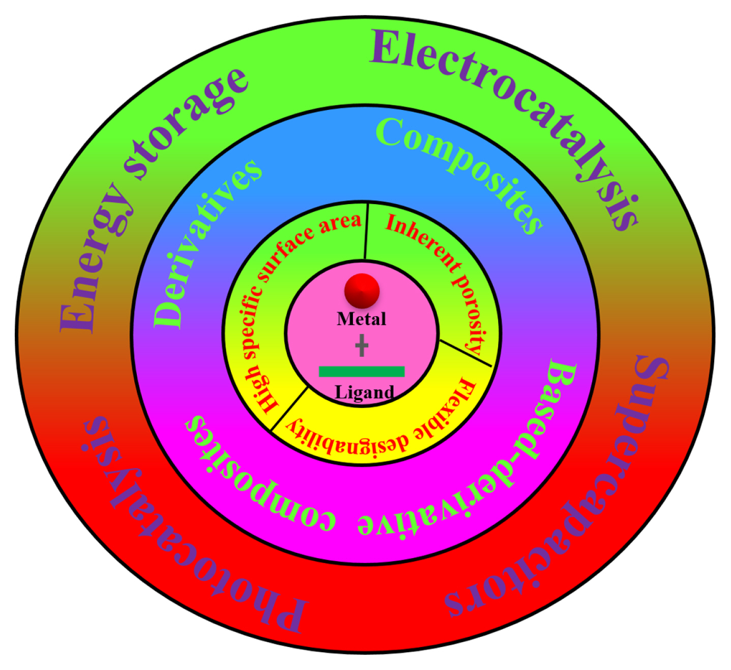
A schematic illustration of MOFs synthesis, properties, and applications.
MOFs are mainly divided into two-dimensional (2D) MOFs and bulk three-dimensional (3D) MOFs by morphology [11]. The synthetic methods of 2D MOFs mainly include top-down and bottom-up methods. The top-down method mainly include chemical exfoliation, delamination, mechanical exfoliation and sonication exfoliation, which means that the layer nanostructure MOFs can be exfoliated by breaking the weak interlayer interactions [11]. The reported synthesis methods of 3D MOFs are various, such as classical hydrothermal synthesis, solvothermal synthesis, microwave heating, diffusion, ultrasonic, mechanochemical and electrochemical synthesis. Most 3D MOFs belong to octahedral, polyhedral and dodecahedra structure, causing low conductivity and limiting application in glucose monitoring, despite their good stability [13]. The interconnected open pores and rich redox sites of most 2D MOFs are beneficial for electrocatalytic activity. However, 2D MOFs are prone to restacking, causing lower stability than 3D structures. Overall, poor electronic conductivity and low mechanical stability greatly limit MOFs applications for glucose sensors [11]. Up till now, scientist have proposed many strategies to enhance the electrocatalytic activity of MOFs, such as the introduction of halogens or inorganic ligands, the pyrolysis of MOFs to form porous carbon-based materials, the doping of metals, the engineering of defects, the etching of organic weak acid and the combining with carbon rods or graphene [11,13]. Especially, it is promising to engineer the hierarchical 3D MOF nanostructures which maintain the stable structures of 3D MOFs and inherit the excellent features of 2D MOFs, such as large surface area, rich redox sites and interconnected open pores.
In this review, we mainly make a brief overview of the development of glucose non-enzyme sensors based on MOFs in recent years. We discuss the sensing performance, the shortcomings and future development prospect of MOF-based materials in nonenzymatic glucose sensor field. We also discuss the future challenges of MOF-based materials to build high performance glucose sensor.
2. Sensing mechanism of MOF-based materials for glucose electrochemical detection
2.1 Mutarotation of glucose
The chemical formula of glucose is C6H12O6, which plays an important role in the normal functioning of the human body. As shown in Fig. 3, the glucose molecule has five different isomers in aqueous solutions, including γ-D-glucose, α-D-glucofuranose, α-D-glucopyranose, β-D-glucofuranose and β-D-glucopyranose. Among of them, the glucose mainly naturally exists in the form of γ-D-glucose with the open-chain aldehyde structure [1,14]. The mutarotation process means the mutual transformation of five isomers to reach equilibrium state in aqueous solution, which is a rather slow process (e.g., 2 h at room temperature) [14]. The equilibrium ratio of five isomers is greatly affected by the solution environment, such as temperature, pH and the coexisting ions. The glucose is finally transformed into D-gluconic acid after hydrogen abstraction and hydrolysis process. It’s noted that the rate of glucose oxidation is mainly determined by the abstraction of the H atom at C-1 [15].

Five isomers structures of D-glucose in aqueous solution. The functional groups at carbon atom 1 (C-1) are highlighted by red or blue color. The equilibrium ratio of each isomer under standard temperature and pressure is represented by the number in parentheses.
2.2 Mechanisms of non-enzymatic glucose sensors oxidation
Up till now, there are two glucose oxidation mechanisms widely recognized in glucose sensor field, chemisorption model [1] and incipient hydrous oxide/adatom mediator (IHOAM) model [1,16,17]. The chemisorption model includes two process with reactant molecules attaching to the active sites of electrode and the reaction product desorbing from the electrode surface, which greatly affected by the electronic states of redox center, the unfilled d orbitals of transition metal centers and the number of defects in catalysts [1]. Fig. 4(a) demonstrates the chemisorption mechanism of non-enzymatic glucose sensors. When the glucose molecule is close to the electrode, the chemical interaction between the glucose molecule and the electrode is strong enough that the C-1 and its H atom are adsorbed to the electrode surface accompanied by the bond breaking between the C-1 and its H atom [1]. Then, the adsorbates are oxidized by the redox centers of electrode, causing the production of glucono-d-lactone which is further oxidized into gluconic acid through various reaction pathways determined by the PH of solution [1].
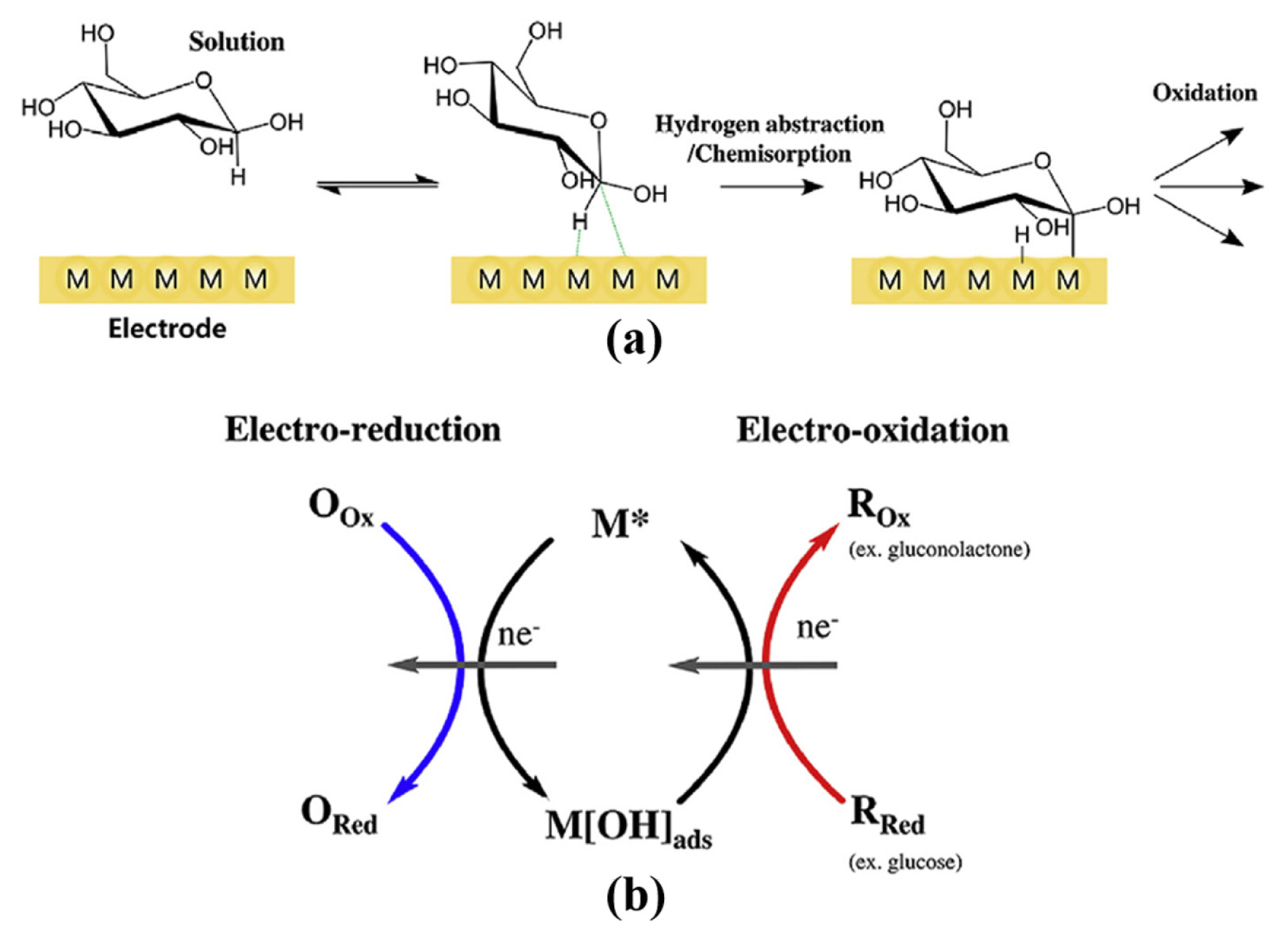
(a) Chemisorption mechanism and (b) incipient hydrous oxide/adatom mediator model.
Burke et al. firstly proposed the IHOAM model in order to complete the complex electrocatalytic process along with the chemisorption-based model [17]. Then, many scientists confirmed the correctness of the IHOAM model by oxidation procedures of various metal electrodes. Fig. 4(b) demonstrates the electrocatalytic process of IHOAM model. It’s noted that the reactive hydroxide species (OHads) generated during electrocatalysis process can directly oxidize the reactants [1,17]. The formation of OHads is more favorable in alkaline condition than in neutral or acidic condition [1,17]. Besides, the chemisorption and the IHOAM models are applicable to noble metal, some transition metals (e.g., Ni, Co, Cu), platinum group metals and their oxides electrodes, while both of them are not applicable to most transition metals and transition metals oxides electrodes [1,17].
2.3 Influencing factors of non-enzymatic glucose sensors
The pH value, scan rate, sensitivity, detection limit and selectivity have great influence on the electrocatalytic performance of non-enzymatic glucose sensors [3]. As for non-enzymatic glucose sensors with noble metal ions and platinum group metals ions as oxygen-reduction center, the electrolyte pH value is usually among 13–14, because the noble metal ions and platinum group metal ions only oxide the glucose under alkaline condition [1,4]. The electrode reaction kinetics can be obtained by scan rate method, as a result for obtaining the relationship between the response current and the scan rate. On the one hand, the linear relationship between the response current and the square root of the sweeping velocity, suggests that a diffusion controlled redox reaction occurs on the electrode [11,18]. On the other hand, the linear relationship between the response current and the scan rate demonstrates an adsorption controlled redox reaction on the electrode.
As for each of biofluidic analytes, the glucose concentration is 2–40 mM in blood, 0.01–1.11 mM in saliva, 0.008–1.77 mM in sweat for diabetics, so the detection range of device should be enough accordingly [7,10,19,20]. Excellent sensitivity indicates that the device can make a quick response for glucose. Moreover, the ingredients of blood are very rich, such as glucose, inorganic salt ions, ascorbic acid, urea, uric acid and so on [8]. Saliva and sweat also have a variety of ingredients. These interferences should be fully considered in selectivity experiments for glucose sensors. The selectivity property of materials mainly depends on its intrinsic properties (crystal structure, interaction between atoms, etc.), while it is also affected by the solution pH, reaction time and products have in a certain degree [1]. To sum up, the excellent selectivity and sensitivity and enough detection range of glucose device are recognized as a strong guarantee for accurate detection results.
2.4 Electrochemical techniques for glucose sensors
Up till now, the research methods of electrochemical sensors are classified into cyclic voltammetry, differential pulse voltammetry, electrochemical impedance spectroscopy, linear sweep voltammetry and amperometric response methods [4,7].
The cyclic voltammetry method is not only widely used to study the mechanisms of electrochemical reactions, the properties and the kinetic parameters of glucose sensor electrode, but also to research the linear relationship between glucose concentration and electrochemical signal [21,22]. The differential pulse voltammetry method can be used to analyze trace, due to its high detection sensitivity and low detection limit. According the electrochemical impedance spectroscopy method, the conductivity of electrode, the sensor assembly process and the change of impedance can be obtained [21,22]. The linear sweep voltammetry method is rarely used in non-enzymatic glucose sensor related experiments, although it has the ability of measuring the corresponding polarization current at different potentials [4,22]. Amperometric response method is frequently used in glucose sensor study and anti-interference research. According this method, the i–t curve of current variation with time and the linear relationship between glucose concentration and electrochemical signal can be obtained [4,22].
3. MOFs and their composite materials as sensing materials for non-enzymatic glucose sensors
Although the research of bimetal MOFs or monometallic MOFs as catalytic reaction center is abundant, the electrocatalytic performance of synthesized MOFs is still far from commercial requirements, closely related to poor stability and low conductivity of MOFs. Scientists have made a lot of efforts to improve the sensing performance of MOFs, such as, morphology modifying, high temperature calcination, the introduction of materials with excellent conductivity, in-situ growth method to reduce resistivity and so on [4,22]. This review also aims to discuss the sensing performance of MOFs for non-enzymatic glucose sensor in recent years, and discuss the perspectives and future challenges of them.
3.1 The MOF-based composites for non-enzymatic glucose sensors
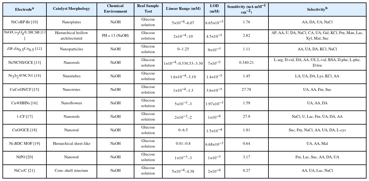
The design engineering of novel composite materials composed of high conductivity materials (e.g., graphene, carbon cloth, carbon rods, copper foam and nickel foam) and MOFs, is one of the current research hotspot [21]. The shape of representative sample of MOFs-based composite is shown in Fig. 5(a). On the one hand, MOFs with heterojunction structure show better chemical stability and lager conductivity than pure MOFs. On the other hand, the ordered permutation of MOFs can be effectively improved by growing on carbon cloth, benefiting to improve the electrocatalytic performance of MOFs. Therefore, MOF-based composites are widely recognized as a promising material for glucose detection [7]. Table 1 summarizes the MOF-based composites non-enzymatic glucose sensors for the sensing of glucose levels in alkaline condition.
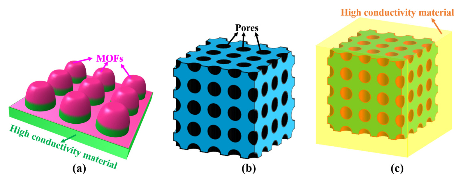
The shape of representative sample of (a) MOFs-based composite, (b) MOFs-based derivatives with abundant pores, and (c) MOFs-based derivative composite.

The performance of MOF-based composites for non-enzymatic glucose sensors
MOFs growing on materials with high degree of order, is a good strategy for enhancing sensitivity property. Zha et al. constructed a two-dimensional nanosheets array formed of bimetal NiCo-BTC MOFs and carbon cloth (CC) by morphology control method for glucose sensor application, as shown in Fig. 6(a) [23]. NiCo-BTC/CC with a highly sensitivity of 2.70 mA mM−1 cm−2, which is about 2.4 times as much as its unregulated counterpart (1.13 mA mM−1 cm−2) in the linear range 5–205 μM, benefiting from the regular and ultrathin nanosheets array. The linear range and detection limit of NiCo-BTC/CC are 5×10⁻³–0.2 mM and 9×10⁻⁵ mM, respectively [23]. Besides, they successfully prepared a noninvasive sweat glucose sensor based on a NiCo-BTC/CC electrode (see Fig. 6(b)), the glucose test results are consistent with commercial invasive glucose device. Compared with the NiCo-BTC/CC, the electrocatalytic performance of this noninvasive sweat glucose sensor needs improvement, closely related to the fabrication technology of sensors [23]. A novel composite Cu-MOF/CC consisting of nanosheet Cu-MOF and carbon cloth (CC) was successfully fabricated by in situ deposition, indicating the potential application of in situ method for glucose sensors [24]. Fig. 7 exhibits the experimental diagram of Cu-MOF/CC. In addition, the sensitivity of Cu-MOF/CC is 3.35 mA mM−1 cm−2 in the linear range 1×10⁻³–0.1 mM, and the sensitivity is 3.81 mA mM−1 cm−2 in the linear range 0.1–1 mM. The material with heterojunction structure usually has excellent conductivity, due to low band gap, as a result of the components of the heterojunction with similar lattice constants [24].

(a) Fabrication process of NiCo-BTC/CC. (b) SEM image of NiCo-BTC/CC. (c) Measurement process of noninvasive pressure sweat sensor.
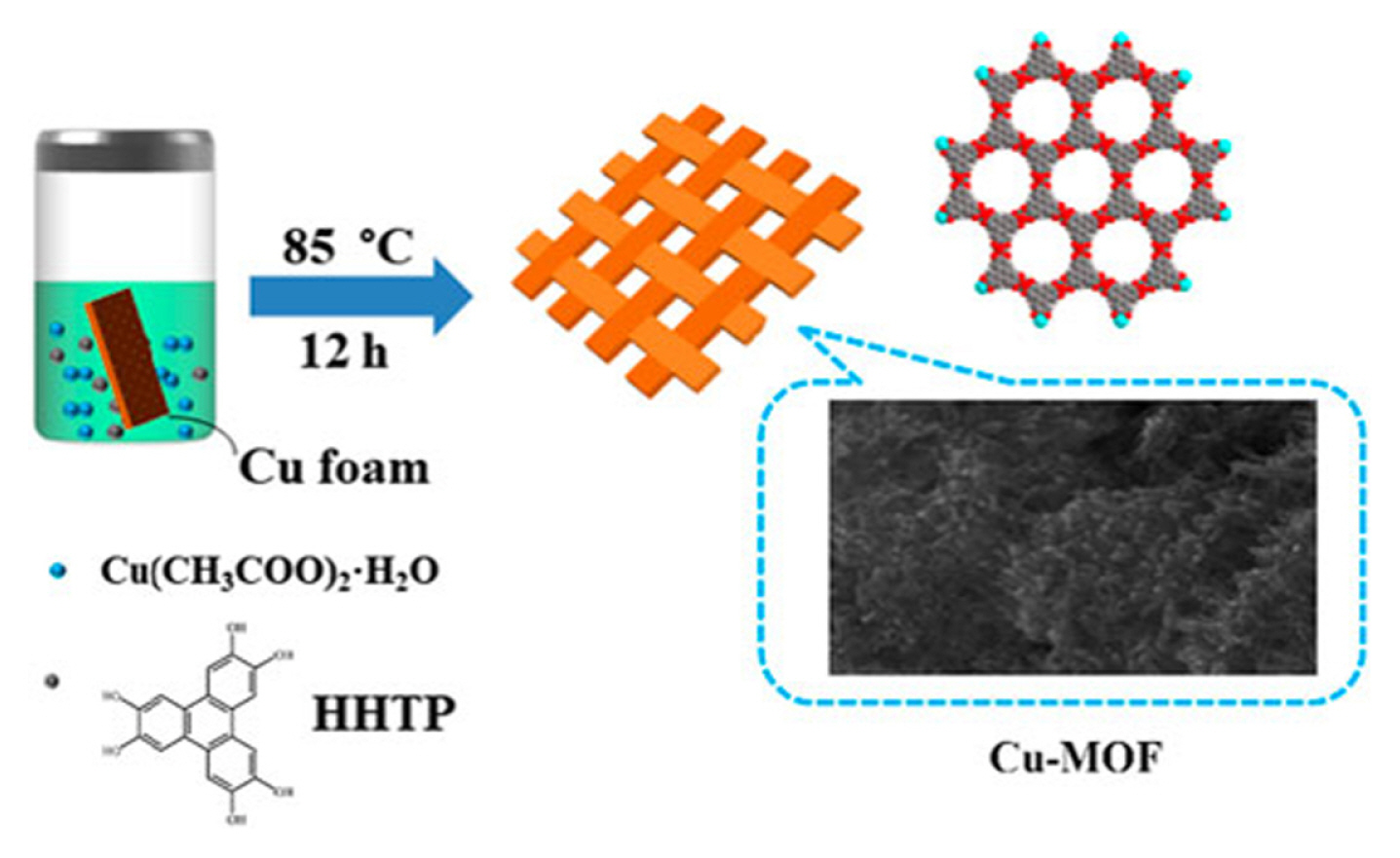
The fabrication process and structure of Cu-MOF/CC.
The pore size and the number of pores play a vital role in the number of active sites for MOFs, closely related to the sensing performance of MOFs. Therefore, modifying pore size or suitably increase the number of pores is a good strategy for enhancing the sensing performance of MOFs. Meng et al. anchored Co coordination polymer spheres (CPS) onto 3D macroporous carbon (MPC) support to synthesis the novel CPS/MPC composites, which combines the electrocatalysis advantages of CPS and MPC [25]. Fig. 8 demonstrates the preparation of CPS/MPC materials. MPC provides a large number of active sites for CPS and more channels for charge transport, resulting in excellent electrocatalytic performance of MOFs. The fast response time 1.713 s of Co CPSs/ MPC, a strong current signal produced by glucose oxidation and negligible response for interferences, indicates Co CPSs/MPC with the fast catalytic efficiency and excellent selectivity for glucose oxidation (see Fig. 8(b,c)) [25]. The formula of layered double hydroxide (LDHs) is M(OH)2, where M is metal ions. Porous LDHs with 2D nanosheets, show excellent characteristics such as ease of preparation, great physical stability, cost-effectiveness and ion penetration, because of their hydrophilic nature. Martin et al. grew CoZn-LDHs on the GCE surface and then transformed CoZn-LDHs into CoZn-BTC via acid-base reaction, as shown in Fig. 9(a)[26]. The sensitivity of CoZn-BTC/GCE is 1.22 mA mM−1 cm−2 in the linear range 0.001–0.26 mM, and the sensitivity is 0.51 mA mM−1 cm−2 in the linear range of 0.26–2.53 mM (see Table 1) [26]. As exhibited in the Fig. 9(b), the amperometric response toward the injected glucose is greatly higher than the other interferences, indicating the excellent selectivity of CoZn-BTC/ GCE. Besides, the glucose is successfully measured by CoZn-BTC/GCE electrode in human blood serum, urine and saliva samples without any sample preprocessing (see Fig. 9(c–e)) [26].
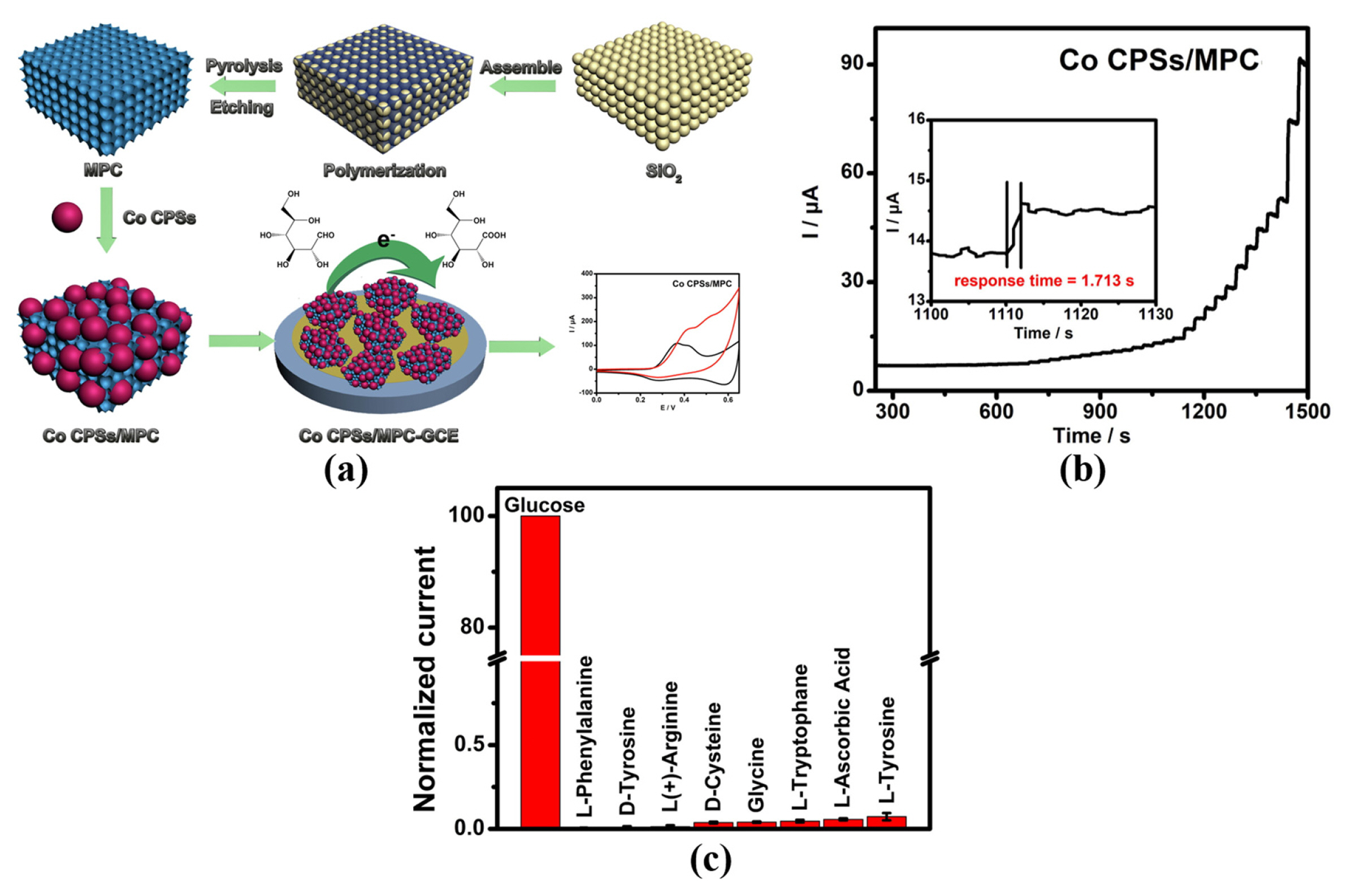
(a) Experimental synthesis Co CPSs/MPC. Current responses of Co CPSs/MPC-GCE with (b) successive addition of glucose and (c) the addition of several possible interferences.

(a) Illustration of fabricating procedure for CoZn-BTC/GCE. (b) Current responses of the CoZn-BTC/GCE with the addition of glucose solutions and fructose, galactose, sucrose, lactose, AA, UA, DA, and NaCl into 0.1 M NaOH at 0.6 V. Current responses of the CoZn-BTC/GCE in 50 μL (c) human blood serum, (d) human urine, and (e) human saliva, following by injection of 200 μM standard glucose solutions into 0.1 M NaOH at 0.6 V.
From the above results, the combination of high conductivity or high porosity materials [23], the use of LDH as sacrificial templates [26] and the designed selection engineering of metal ions and organic ligand [25,27] can effectively enhance the sensing performance of MOF-based glucose sensors.
3.2 The MOF-based derivatives for non-enzymatic glucose sensors
MOFs are widely recognized as ideal sacrifice templates to produce novel material for glucose sensing, due to the structural designability of MOFs. The MOF-based derivatives can be produced by introduction of other elements (such as transition metal elements, halogen elements and nonmetallic elements) [28,29], weak acid etching and calcination strategies. Up till now, the research of MOFs derivatives mainly focuses on the metal oxides produced by calcination method. Fig. 5(b) illustrates the shape of representative sample of MOFs-based derivatives with abundant pores. The investigation of novel MOFs derivatives is meaningful for glucose sensors and an unexpected discovery may be obtained. Table 2 summarize the performance of MOF-based derivatives for enzyme free glucose sensors.
The performance of MOF-based derivatives for non-enzymatic glucose sensors
The surface halogenation or doping with metals strategy is an effective method to improve the structural stability, generate more active sites, and enhance glucose adsorption of MOFs [28,29]. The introduction of pyridine can prevent the growth of MOFs in a vertical direction to form the 2D structure. 2D nanoplates NiCoBP-Br is synthesized by pyridine-modulated and surface halogenation method, as shown in Fig. 10(a) [29]. The sensitivity of NiCoBPBr is 1.76 mA mM−1 cm−2 in the linear region 5×10⁻⁴–6.07 mM, and the LOD is 6.65×10⁻⁵ mM. NiCoBPBr/ GCE produced an obvious current response for glucose oxidation, while produced a minimal current response for interferents (see Fig. 10(b)) [29]. Besides, Fig. 10(c) demonstrates that the response time of NiCoBP-Br/GCE is less than 2 s. These results indicate NiCoBP-Br with excellent electrocatalytic performance for glucose application can be obtained by 2D MOF structure designing [29]. Kim et al proposed that doping Zn element can enhance the chemical stability and electrocatalytic capacity of ZIF-67, due to the strong bonds between Zn and the N atoms in ZIF-8 and bimetallic synergies. Nanoporous carbon (NC) materials have attracted great attention in glucose sensor filed, due to its high specific surface area and optimized pore size distributions [28]. Among of ZIF-ZnxCo1−x materials (0 ≤ x ≤ 1), ZIF-Zn0.5Co0.5 was selected as the optimal glucose sensing material, because of its high Co2+ content and well preserved porosity and crystallinity [28]. The excellent sensitivity of ZIF-Zn0.5Co0.5 is 1.11 mA mM−1 cm−2 in the linear region 0–1.25 mM, and the LOD is 9×10⁻³ mM. Fig. 11(a) demonstrates that the current responses of ZIF-Zn0.5Co0.5 for interfering species is negligible, while glucose reproducibly induced sharp current responses, indicating ZIFZn0.5Co0.5 with excellent selectivity for glucose [28]. Besides, ZIF-Zn0.5Co0.5 maintained its sensitivity after five repeated measurements, and its relative standard deviation is only 1.3%, indicating its electrochemical stability and excellent reusability (see Fig. 11(b)) [28].
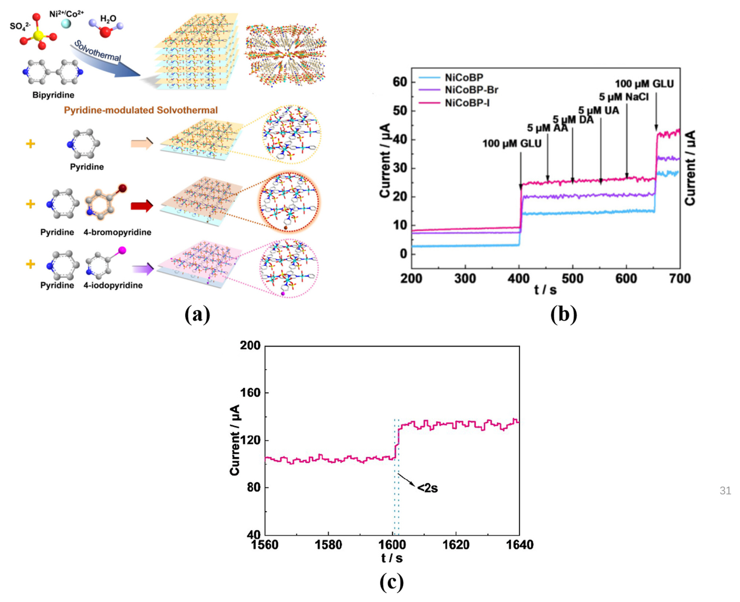
(a) Schematic illustration of the synthetic strategy of the cuboid NiCo-B MOFs and the NiCo-BP, NiCoBP-Br, and NiCoBP-I nanoplates. (b) Current responses of the NiCoBP, NiCoBP-Br, and NiCoBP-I GCE with successive injections of glucose, AA, DA, UA, NaCl, and glucose into 0.1 M NaOH at 0.55 V. (c) Response time for NiCoBP-Br GCE with the addition glucose solution.

(a) The interference assessment of ZIF-Zn0.5Co0.5 selectivity for with the succeeding insertion of various analytes and glucose. (b) The reusability tests of ZIF-Zn0.5Co0.5: five successive CA measurements of glucose sensing.
Metal oxide or metallic sulfide produced by calcination strategy, have more pores than pure MOFs. The more pores are, the more ion transport channels are, enhancing the conductivity of compounds [30–34]. Vignesh et al. used NiCo-MOF as sacrificial template to produced NiO/Co3O4/C with hierarchical hollow architecture, and then loaded it on biodegradable garbage bag/biodegradable corn starch bag (BCSB) to form a disposable, bendable and low cost glucose sensor [30]. Fig. 12(a,b) exhibit the TEM images of NiCo MOF and NiO/Co3O4/C. The shape of NiCo-MOF is spherical with the smooth surfaces, while the shape of NiO/Co3O4/C is spherical shaped hollow spherical with the rough surfaces, provided the continual electron mobility and catalytically active channels [30]. Fig. 12(c) demonstrates the glucose oxidation mechanism of NiO/Co3O4/C/BCSB. When the glucose is close to the electrode, the high oxidation states of metallic centers (Ni(III)/Co(IV)) oxide glucose, producing lower oxidation states (Ni(II)/Co(III)) and glucolactone. NiO/Co3O4/C/ BCSB has negligible amperometric responses for interferences, while it has significant responses for glucose, as shown in Fig. 12(d). In addition, Fig. 12(e) demonstrates that NiO/Co3O4/C/BCSB has the capacity for the superior Cl− poisoning resistance [30]. The excellent sensitivity of NiO/Co3O4/C/ BCSB is 2.82 mA mM−1 cm−2 in the linear region 2×10⁻⁴–10 mM, and the LOD is 4.5×10⁻⁵ mM [30]. Jia et al. used Ni-MOF as sacrifice templates to produce Ni nanoparticle embedded on nanoporous carbon nanorods (Ni/NCNS) by pyrolysis method (T = 500°C), as shown in Fig. 13(a) [31]. The response times of Ni/NCNs/GCE is 1.6 s, indicating the modified electrode with rapid and sensitive current response for glucose, as shown in Fig. 13(b). Besides, Ni/NCNs/GCE show outstanding anti-interference and selectivity properties (see Fig. 13(c)) [31].

TEM images of (a) Ni-Co MOF and (b) NiO/Co3O4/C. (c) Electrocatalytic mechanism of NiO/Co3O4/C/BCSB. (d) Interference tests of NiO/Co3O4/C/BCSB with successive injections of glucose and interfering agents (pH=13) at 0.6 V. (e) Amperometric behavior of NiO/Co3O4/C/BCSB for variant glucose concentration (pH=13) in the lack and manifestation of 0.1 M NaCl at 0.6 V.

(a) Experiment preparation of Ni/NCNs composite. (b) Amperometric response of Ni/NCNs/GCE on successive droppings of various glucose concentrations at 0.55 V (inset: the response time of Ni/NCNs/GCE for glucose oxidation). (c) Selectivity test of Ni/NCNs/GCE for glucose exposed to several interferences.
The hydrophilicity property of MOFs mainly depends on surface morphology, which also has great influence on the adsorption of glucose [35]. ZIF-8 is widely recognized as a promising material for glucose sensor application, due to its sturdy porosity, excellent thermal and chemical stability. However, the pores of ZIF-8 are smaller than 2 nm, hindering the incorporation of large-sized guest nanoparticles and restrict the diffusion efficiency of reactants and products. Zhu et al. proposed that hydrophobic ZIF-8 crystal can be engineered to be hydrophilic hierarchically-porous nanoflowers (HHNs) by using an organic weak acid as etchant, as shown in Fig. 14(a) [35]. ZIF-8 belongs to uniform rhombic dodecahedron structure, while the HHN is in the shape of 3D hierarchical sheet-like structure. This result indicates that organic weak acid etching method can effectively change the morphology of materials. Besides, the Cu@HHNS maintain the 3D hierarchical sheet-like structure (see Fig. 14(b–d) [35]. The excellent sensitivity of Cu@HHNS is 1.59 mA mM−1 cm−2 in the linear region 5×10⁻³–3 mM, and the LOD is 1.97×10⁻³ mM. In addition, the Cu@HHNs show excellent selectivity for glucose, as shown in Fig. 14(e) [35].

(a) The reconstruction scheme of hydrophobic ZIF-8 crystal into hydrophilic hierarchy porous nanoflowers. FE-SEM images of (b) ZIF-8, (c) HHNs, and (d) Cu@HHNs. (e) Chronoamperometric response of the Cu@HHNs based sensor on successive droppings of glucose, UA, AA and DA into 0.1 M NaOH at 0.6 V.
In conclusion, pyrolysis with high temperature and special gas [30,33], surface halogenation [29], weak acid etching [35] and S doping [32] are good strategies to produce derivatives of MOFs with promising electrocatalytic performance for non-enzymatic glucose sensors.
3.3 The MOF-based derivative composites for non-enzymatic glucose sensors
The derivative of MOFs combined with graphene, double hydroxides, copper foam and nickel foam, also presents a promising prospect for glucose sensor application [36–38]. However, compared with the pure derivatives and composites, the fabrication of MOF-based derivative composites is more complex, not conducive to practical application for glucose sensors. Fig. 5(c) represents the shape of representative sample of MOF-based derivative composite. The performance of some derivatives of MOF-based composites as glucose sensors are shown in Table 3.
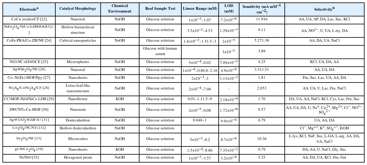
The performance of derivatives composites MOF-based for non-enzymatic glucose sensors
Mostly used nanoporous metal electrodes are copper foam and nickel foam at present. Nanoporous metal electrodes not only can provide abundant active sites and ion transport channels for MOFs, but also can reduce collapse and reunion of MOFs, beneficial to sensing performance of sensors. Besides, nanoporous metal electrodes can reduce the use of Nafion binders, as a result for reducing the resistivity of sensor device. However, MOFs uniformly grows or do not grow on the porous electrode are commonly problem. The addition of morphology modifier is a good strategy to solve this problem. Cu(OH)2 nanorod arrays as sacrificial template to fabricate MOF-derived metal oxides with well-ordered architecture, has attract a lot of attention. Cu(OH)2 nanorod arrays grew on Cu foam by in-situ growth method and then used as sacrificial template to synthesize CoCu-MOF/Cu2O nanorod arrays [36]. Porous CoCu oxides (Co3O4, CuO and Cu2O) were obtained after the annealing of CoCu-MOF/Cu2O (see Fig. 15(a)) [36]. Wei et al. also found that annealing temperature has great influence on the morphology of CoCu-MOF/Cu2O, and the preferred annealing temperature was 350°C. Besides, CoCu oxides/CF show excellent selectivity, long-term stability and good reproducibility (see Fig. 15(d–f)) [36]. Chu et al. successfully fabricated NiFe2O4-NiCo-LDH@rGO composite with a hollow hierarchical structure by pyrolysis and hydrothermal methods [37]. Fig. 16(a) demonstrates the experimental procedure of NiFe2O4-NiCo-LDH@rGO composite. The surface of NiFe2O4 is rougher than parent NiFe-MOF, while NiFe2O4 still keep the cubic structure (see Fig. 16(b,c)) [37]. Fig. 16(d) demonstrates that NiCo-LDH nanosheets interconnect with each other, grow on the surface of NiFe2O4 to forming a flowerlike hierarchical structure with highly porous surface [37]. In addition, Fig. 16(e) confirmed the hollow hierarchical structure of NiFe2O4-NiCo-LDH@rGO composite. NiFe2O4-NiCo-LDH@rGO shows excellent selectivity towards general interfering species, as shown in Fig. 16(f)[37]. The catalytic capability of NiFe2O4-NiCo-LDH@rGO composite still retains 95.70% after stored 19 days and tested many times, implying NiFe2O4-NiCo-LDH@rGO with good capacity of long-term storage and operational stability (see Fig. 16(g)) [37].

(a) Schematic illustration of the fabrication process of CoCu oxides/CF. (b) SEM images of Cu(OH)2/CF. (c) SEM and TEM images of CoCu oxides/CF. (d) Amperometric response of 5 CoCu oxides/CF electrode towards glucose in presence of. (e) Stability of 5 CoCu oxides/CF electrode in three weeks. (f) Current responses of 5 CoCu oxides/CF electrodes exposed to 6 μL of 0.5 M glucose in 0.1 M NaOH at 0.5 V.

(a) Fabrication procedure of NiFe2O4-NiCo-LDH@rGO. SEM images of (b) NiFe-MOF, (c) NiFe2O4 (inset is the hollow NiFe2O4) and (d) NiFe2O4-NiCo-LDH. (e) TEM Pattern of NiFe2O4-NiCo-LDH@rGO. (f) Interference test for the NiFe2O4-NiCo-LDH@rGO with the addition of glucose, AA, NO2−, UA, L-Try, DA. (g) The catalytic efficiency of the NiFe2O4-NiCo-LDH@rGO/GCE in 19 days in 0.1 M NaOH with 0.10 mM glucose.
In conclusion, well-ordered materials as sacrificial template [36], calcination [37,39], the doping of nonmetallic elements [40] and the combination with Cu foam or Ni foam [36,38], are good strategies for the fabrication of novel materials as glucose sensor. Besides, it’s meaningful to investigate simple and practicable fabrication of MOF-based derivative composites for glucose sensor commercial application.
3.4 Stability, advantages and disadvantages of MOFs-based compounds
Stability issue is a common and serious concern, not only in enzyme sensor but in non-enzymatic sensor. As for the commercial enzyme sensor, the test paper attached with enzymes display strong stability for up to one or two years. The summary of the long-term stability of electrodes based on MOFs is shown in Table 4. As for the most composites based on MOFs, they show poor stability for around one month, far short of the performance standards for commercial enzyme sensor. Thus, it is an important and difficult task to improve the chemical stability of electrodes based on MOFs in order to push them closer to practical application of glucose detection.

The summary of long-term stability of MOFbased composites, MOF-based derivatives and MOF-based derivative composites for glucose sensing. The values of bracket represent the initial response current retention
MOF-based composites are usually formed by pristine MOFs and high conductivity materials, such carbon cloth, copper foam and nickel foam. As for MOF-based derivatives, there are mainly three production strategies, high temperature pyrolysis, surface vulcanization, and surface halogenation. As for MOF-based derivative composites, its structure and synthesis method are more complex than that of other two materials. Besides, Table 5 summaries the advantages and disadvantages of MOF-based derivatives and MOF-based derivative composites for glucose sensing.
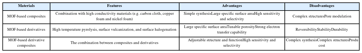
The summary of the advantages and disadvantages of application of MOF-based composites, MOF-based derivatives and MOF-based derivative composites for glucose sensing
As for a continuous glucose monitoring system, it mainly includes two parts, test system and data display system. The accuracy of test results is mainly determined by test system. As for the test system, it mainly includes two parts, electrodes and signal processing system. MOFs are widely recognized as promising materials for electrodes due to its large surface areas and ordered porous structure. The sensing performance of MOFs is mainly determined by fabrication process. The MOFs-based electrodes play a catalytic role in sensor, oxidizing glucose into glucolactone and meanwhile producing response current analyzed by a signal processing system. To sum up, if the problems that the fabrication process of MOFs and MOFs-based electrodes and the compatibility between MOFs-based electrodes and signal system, are well solved, the sensing performance of sensor will be excellently improved.
4. Conclusions and outlooks
The sensing performance of MOFs-based composites plays a vital role in glucose sensor devices with the development of materials and device preparation method in recent years. High performance MOF based composites such as NiCo-BTC/CC, Cu-MOF/ NF, NiCu-MOF, NiCoBP-Br, CoFe-PBA/Co-ZIF/NF have been prepared successfully. Besides, good strategies such as calcination, surface halogenation, weak acid etching, well-ordered materials as sacrificial template and ions doping are introduced to produce novel MOFs-based materials with promising electrocatalytic performance for enzyme free glucose sensors. In general, the sensitivity, detection range and LOD of synthesized materials based on these MOFs sufficiently reach up to the detection requirements of glucose concentration in blood, saliva, sweat and tissue fluid, which would speed up actual application of MOF based materials for non-enzymatic glucose sensors.
Although the MOF-based composites are widely recognized as potential clinical candidates for nonenzymatic glucose sensors, there are many challenges with urgent solution in order to realize commercial application:
As for the MOF-based materials, most physiological body fluids are must preprocessed before glucose detection. The stability and service life of MOF composites are also far from the commercial demand of glucose sensor. Both of them indicate the limitation of materials MOF-based in glucose sensor application at present.
As for noninvasive detection method (saliva, sweat, etc.), the relationship between the saliva (sweat) glucose level and blood glucose concentration is controversial, due to the differences of individual and test environment.
The alkaline condition of chemical environment vastly limit the application of wearable glucose sensor based on MOFs, because this condition will cause the corrosion of skin once leaked. However, the handheld and portable device is more safe than wearable device, due to not close to skin.
The sensing performance of device determined by signal amplifying circuit, internal resistance of the whole circuit, device assembly technology and body fluid collection process, is worse than that of pristine materials, hindering the development of glucose sensor device. Hence, it’s vitally important to improve and optimize the fabrication engineering of nonenzymatic glucose sensor for enzyme free glucose sensor application.
Therefore, most investigations should focus on improving the stability, selectivity and survey life of MOF-based composites in alkaline solution in future. As for the body fluid-based glucose sensor, it should consider the individual differences and construct universal algorithm for the relationship between body fluid glucose concentration and blood glucose level. Besides, the development of MOFs material-based sensor device also trends toward intelligence, portability and function integration.
Availability of data and material
All data is given in the manuscript.
Acknowledgments
This work was supported by the National Natural Science Foundation of China (61971112), Chongqing Postdoctoral Science Special Foundation (Xm2017051), Natural Science Foundation of Chongqing (No. cstc2019jcyj-msxmX0824), Chongqing Scientific Research Fund of Chongqing Municipal Education Commission (No. KJQN201901304), and Chongqing Undergraduate Innovation and Entrepreneurship Training Program (No. 201910642029).
Notes
Conflict of interest
There are no conflicts to declare.