Exploiting Natural Diatom Shells as an Affordable Polar Host for Sulfur in Li-S Batteries
Article information
Abstract
Given the high theoretical capacity (1,675 mAh g−1) and the inherent affordability and ubiquity of elemental sulfur, it stands out as a prominent cathode material for advanced lithium metal batteries. Traditionally, sulfur was sequestered within conductive porous carbons, rooted in the understanding that their inherent conductivity could offset sulfur’s non-conductive nature. This study, however, pivots toward a transformative approach by utilizing diatom shell (DS, diatomite)—a naturally abundant and economically viable siliceous mineral—as a sulfur host. This approach enabled the development of a sulfur-layered diatomite/S composite (DS/S) for cathodic applications. Even in the face of the insulating nature of both diatomite and sulfur, the DS/S composite displayed vigorous participation in the electrochemical conversion process. Furthermore, this composite substantially curbed the loss of soluble polysulfides and minimized structural wear during cycling. As a testament to its efficacy, our Li-S battery, integrating this composite, exhibited an excellent cycling performance: a specific capacity of 732 mAh g−1 after 100 cycles and a robust 77% capacity retention. These findings challenge the erstwhile conviction of requiring a conductive host for sulfur. Owing to diatomite’s hierarchical porous architecture, eco-friendliness, and accessibility, the DS/S electrode boasts optimal sulfur utilization, elevated specific capacity, enhanced rate capabilities at intensified C rates, and steadfast cycling stability that underscore its vast commercial promise.
1. Introduction
Secondary batteries play a pivotal role in the progressive advancements of energy storage systems. Among the plethora of battery technologies, lithium-sulfur (Li-S) batteries have emerged as a promising contender due to their notably higher energy densities compared to other electrochemical systems [1–4]. One significant advantage of the Li-S battery is its cathode material, sulfur, which is both abundant and cost-effective [1–4]. This attribute positions Li-S batteries as a potentially more commercially viable energy storage alternative compared to lithium-ion batteries, which are dependent on scarcer and more expensive materials.
However, Li-S batteries are not without challenges. Chief among these is their propensity for capacity fade and cycling instability [5–7]. Over successive charge and discharge cycles, the sulfur cathode can degrade, leading to a decline in capacity and a subsequent deterioration in battery performance. A multitude of strategies have been explored to mitigate these issues.
Many investigations have focused on a range of host materials, from diverse carbon structures to semiconductive metal oxides, in a bid to encapsulate sulfur and combat capacity fading during cycling [8–14]. For example, carbon materials such as hollow porous carbon, graphene, mesoporous carbon, and microporous carbon have been evaluated, largely due to their effective electron transfer capabilities and intricate porous nanostructures [8–10]. These characteristics render them adept sulfur hosts, which can substantially bolster the performance of Li-S batteries. Furthermore, semiconductive metal oxides like CuO, SnO2, Co3O4, and TiOx have been trialed as potential sulfur hosts [11–14]. In recent times, materials like semiconducting and conducting sulfides, phosphides, carbides, and nitrides have been researched as host materials, either standalone or in conjunction with carbon support [15–17].
Historically, non-conductive metal oxides were sidelined as viable sulfur hosts, primarily owing to misconceptions about the imperative for direct electrical contact between the insulating sulfur and conductive scaffolds, such as carbon, for efficient electrochemical reactions. However, certain oxides, due to their polarity, can provide advantageous hosting properties, aiding in trapping dissolved polysulfide intermediates. Breakthroughs in recent research have integrated oxides like La2O3, TiOx, and SiO2, and natural siliceous minerals (e.g., diatomite) with conductive carbons. These integrations have been instrumental in confining soluble polysulfides within the cathode, thereby minimizing diffusion losses during cycling [18–22].
In recent developments, nonconductive platelet ordered mesoporous silica (pOMS), an innovative class of OMS, has been utilized as a novel host material [23]. Intriguingly, due to its high surface area and polar structure, the nonconductive pOMS surpasses its counterpart, platelet ordered mesoporous carbon (pOMC), in terms of long-term cycle performance [23]. Nonetheless, the synthesis of pOMS can be intricate and often comes with elevated costs, reflecting the challenges faced with many mesoporous carbon materials.
In this study, we unveil a novel approach that merges simplicity in synthesis with cost-efficiency, environmental responsibility, and scalability. Our focus is on harnessing naturally occurring diatom shell (DS, diatomite), which possesses an inherently electrically insulating property, as a sulfur host. Characterized by its thin external layers connected by girdle bands, diatomite features a singular porous structure with pore sizes ranging from 50 nm to over 1 μm [24–26]. This unique configuration has seen application in realms like biosensors and drug delivery [27,28]. Of late, its potential as a cathode additive, in combination with carbon black support to store polysulfide intermediates, has been recognized [22].
In our research, we craft a sulfur-layered diatomite/S composite (DS/S) using the melt-diffusion technique, whereby the surface of the sulfur-infused diatomite particles is layered with sulfur. We present compelling evidence that this composite facilitates the complete involvement of the electrically isolated sulfur in electrochemical reduction to polysulfides, and leverages diatomite’s porosity to sequester soluble polysulfide ions. These findings hint at a revolutionary and simplistic method to enhance the cycle performance of sulfur cathodes, laying the groundwork for cost-effective, large-scale manufacturing.
2. Experimental
2.1 Preparation of Materials and Sulfur Cathodes
The DS/S composite was produced utilizing a standard melt-diffusion approach. A homogenized mixture of pure diatomite (Sigma Aldrich) and sulfur (Sigma Aldrich) at a weight ratio of 1:5 (diatomite to sulfur) was transferred to a Teflon pot. This mixture was subjected to a temperature of 155°C for a duration of 12 hours. To ensure superior quality of the DS/S composite, it was subsequently heated to 250°C for 3 hours in a nitrogen (N2) atmosphere, facilitating uniform diffusion of molten sulfur into the diatomite pores. After this treatment, the composite was left to naturally cool down to ambient temperature.
For the fabrication of the sulfur electrode, a slurry was prepared by dispersing sulfur powder, Ketjenblack (used as a conductive agent), and polyethylene oxide (PEO) binder in acetonitrile in a weight ratio of 5:1:2. This slurry was subjected to continuous agitation for 24 hours, following which it was coated onto carbon-coated aluminum foil. For the DS/S cathode electrode, a slurry composed of DS/S composite, Ketjenblack, and PEO binder in a weight ratio of 6:1:2 was prepared in acetonitrile and followed a similar preparation protocol as the sulfur electrode. In both scenarios, the sulfur content was kept consistent. Electrodes were then fashioned into circular shapes with an electrode punching tool (Hohsen Corp., 16 mm diameter) and subsequently dried at 40°C for 12 hours.
2.2 Characterization and Electrochemical Evaluation
Morphological and structural investigations of both the pure diatomite and the synthesized DS/S composites were conducted using SEM (Hitachi, S–4800) and TEM (JEOL, FE-2010). In addition, EDS analysis was executed on the DS/S cathode post a 24-hour aging period. The crystalline phases present in the materials were identified via XRD (Rigaku 1200) using Cu-Kα radiation and a Ni β-filter, operating at conditions of 40 kV and 20 mA. The DS/S composites were subjected to TGA (Bruker, TG-DTA2000SA) to determine sulfur content. Potential sulfur loss during the electrode drying process was quantified using the Mettler Toledo XSE 105 DU, boasting a readability of 0.01 mg. The Brunauer–Emmett–Teller (BET) specific surface areas for the samples were ascertained through nitrogen adsorption techniques (Micromeritics, ASAP 2020).
Electrochemical assessments were executed using 2032 coin cells, assembled under an argon atmosphere within a glove box. Lithium metal was employed as the anode. Separation between the electrodes was achieved using a Celgard 2400 separator. The chosen electrolyte was a solution containing 1.0 M lithium bis-trifluoromethanesulfonylimide and 0.2 M LiNO3, dissolved in an equal volume mixture of 1,3-dioxolane (DOL) and dimethoxyethane (DME). The volume of electrolyte used in each cell was consistently 70 μL. The testing rates were calibrated according to the sulfur content in the cathode, wherein 1 C equates to 1,675 mAh g−1. The inaugural two cycles were tested at 0.1 C, after which the rates varied from 0.2 to 3 C for the subsequent cycles. The charge and discharge profiles for the cells were meticulously documented using a BaSyTec multi-channel battery tester, with voltage limits set between 1.8–2.7 V.
3. Results and Discussion
In our efforts to design a high-performance cathode material that effectively combats both polysulfide loss and structural strain during charge/discharge cycles, we successfully synthesized a unique DS/S composite. This was realized through a standard melt-diffusion approach (step I) followed by a subsequent heat treatment (step II) at a temperature of 250°C, as illustrated in Fig. 1a.
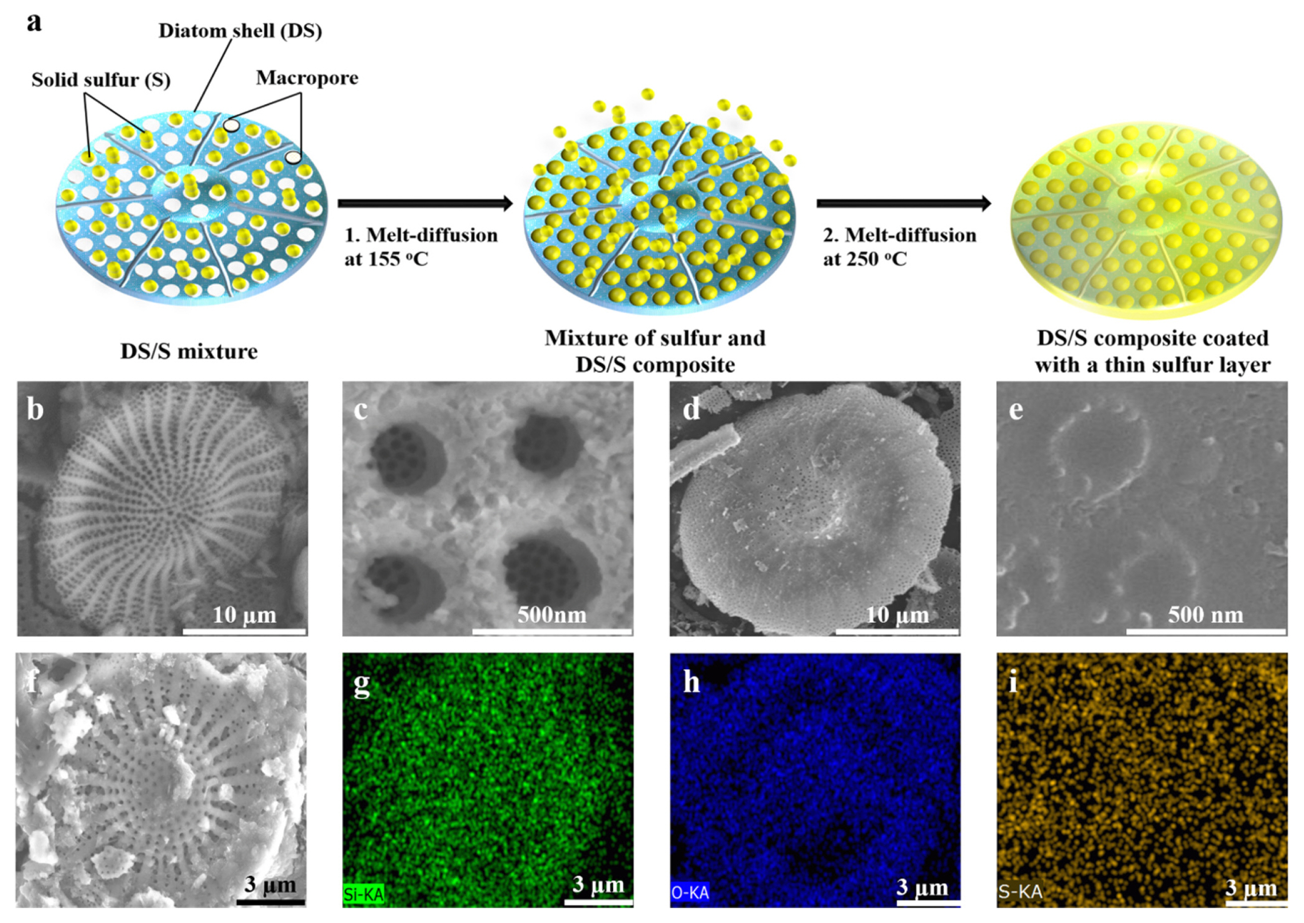
(a) Schematic representation of the melt-diffusion synthesis of the DS/S composite with a thin sulfur layer. (b) Low-magnification SEM image displaying the natural pores of pure diatomite (DS). (c) High-magnification SEM view illustrating mesopores within the prominent macropores of DS. (d,e) SEM depictions of the DS/S composite highlighting sulfur-filled pores, presented at both (d) low and (e) high magnifications. (f) Surface SEM image of the pre-cycled DS/S composite electrode encompassing electrolyte, binder, and conductive carbon. (g–i) Corresponding EDS elemental mappings for (g) Si, (h) O, and (i) S.
Scanning electron microscopy (SEM) results provide evidence that the diatomite exhibits a hollow, disk-like exterior porous layer accompanied by a hierarchically organized porous architecture (Fig. 1b,c). The diatomite’s significant porosity and nanostructure suggest it could serve as an outstanding matrix for sulfur encapsulation and soluble polysulfide adsorption. A deeper dive into its structural attributes showed it possesses a considerable macroporous volume, with a 3D interconnected multimodal porosity that measures from 14 to 28 μm in diameter and spans a thickness ranging from 1.1 to 1.9 μm. Transmission electron microscopy (TEM) imagery further reveals the hierarchical porous nature within the diatomite, displaying macropores from 200 to 320 nm in size that are interconnected with mesopores between 20 and 30 nm (Fig. S1).
The unique 3D hierarchical pore structure, which arises naturally from the self-assembly process steered by diatom metabolism, facilitates optimal sulfur accommodation and soluble polysulfide storage. Worth noting is the abundance of diatomite in nature, eliminating the necessity for the intricate synthesis methods seen in previous researches.
In the course of the melt-diffusion process, solid sulfur was integrated within the diatomite pores. SEM captures (Fig. 1d,e) reveal that the internal pores brim with sulfur, while the exterior surface is uniformly coated by a slender layer of sulfur. Notably, no discernable stand-alone sulfur particles or clusters were identified, even after a meticulous analysis of over 20 samples. To delve deeper into the distribution of sulfur, EDS elemental mapping was performed on the designed DS/S composite electrode (Fig. 1f–i). The results ascertain that the Si, O, and S elements are evenly distributed throughout the diatomite particle.
X-ray diffraction (XRD) patterns, as shown in Fig. 2a, detail the structural characteristics of sulfur, diatomite, and the DS/S composite. The diatomite displays a broad, subdued band at 2θ = 22°, which affirms its amorphous silica structure, referenced by JCPDS card number 29-0085. In the DS/S composite, the sulfur diffraction peaks are notably subdued compared to those of the pristine sulfur, suggesting the presence of crystalline sulfur particles within the DS/S matrix. This inference aligns with the findings from the preceding SEM analysis. The TGA curve illustrates a singular weight loss stage spanning from 200 to 350°C (Fig. 2b). Considering the cumulative weight loss observed at 600°C, we deduce that the sulfur composition is about 83.5 wt%.
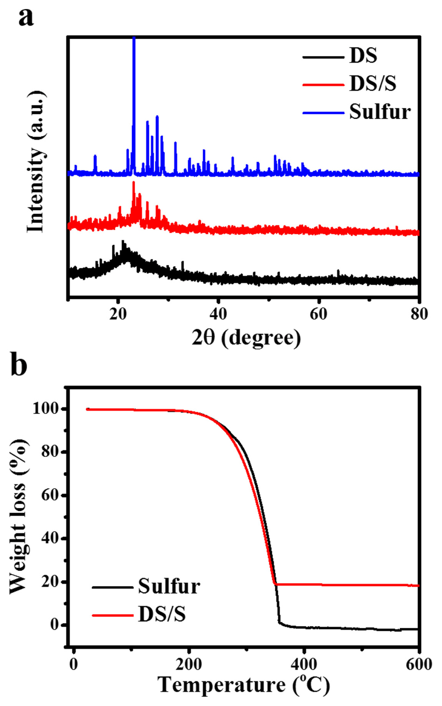
(a) XRD patterns showcasing the crystalline structures of solid sulfur, DS, and the DS/S composite featuring a thin sulfur layer. (b) TGA curves depicting the thermal stability of both solid sulfur and the DS/S composite, conducted under a nitrogen atmosphere.
Using nitrogen sorption isotherms, we assessed the surface area and pore size distribution of the diatomite both before and after sulfur incorporation (Fig. 3). The diatomite’s pore framework was determined via N2 sorption isotherms, revealing a BET specific surface area of 94 m2 g−1 and an aggregate pore volume of 0.36 cm3 g−1. Such a pronounced total pore volume for diatomite suggests its potential as an efficient sulfur host, thereby possibly amplifying the Li-S battery’s cycling stability and energy density. Following the sulfur infusion into the diatomite pores, there’s a marked decrease in the BET surface area and the composite’s total pore volume, registering values of 7.4 m2 g−1 and 0.04 cm3 g−1, respectively. This significant change is attributed to the sulfur’s thorough assimilation within the hierarchical inner pores and the subsequent deposition of a thin sulfur layer atop the diatomite granules (Fig. 3a,b). Drawing from the insights of the nitrogen sorption and TGA analyses, we infer that the proportions of sulfur within the multi-modal pores and those adorning the diatomite exteriors stand at roughly 52% and 48%, in that order.
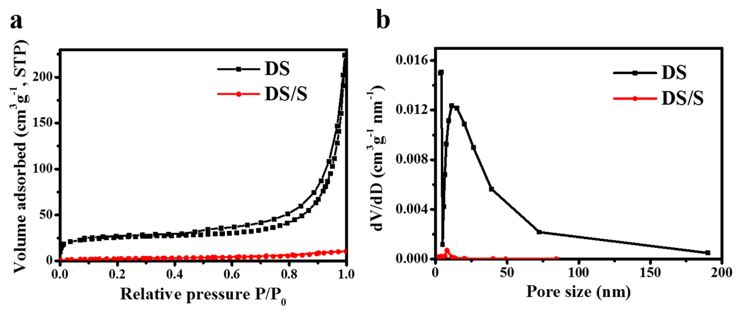
(a) N2 sorption isotherms and (b) pore size distributions of pure diatomite and DS/S composite.
A Li-S battery was fabricated using a DS/S composite cathode, an organic electrolyte, a separator, and lithium, with a conventional sulfur cathode employed as a benchmark. As depicted in Fig. 4a, the discoid porous diatomite serves as an effective host for sulfur during cyclic reactions.
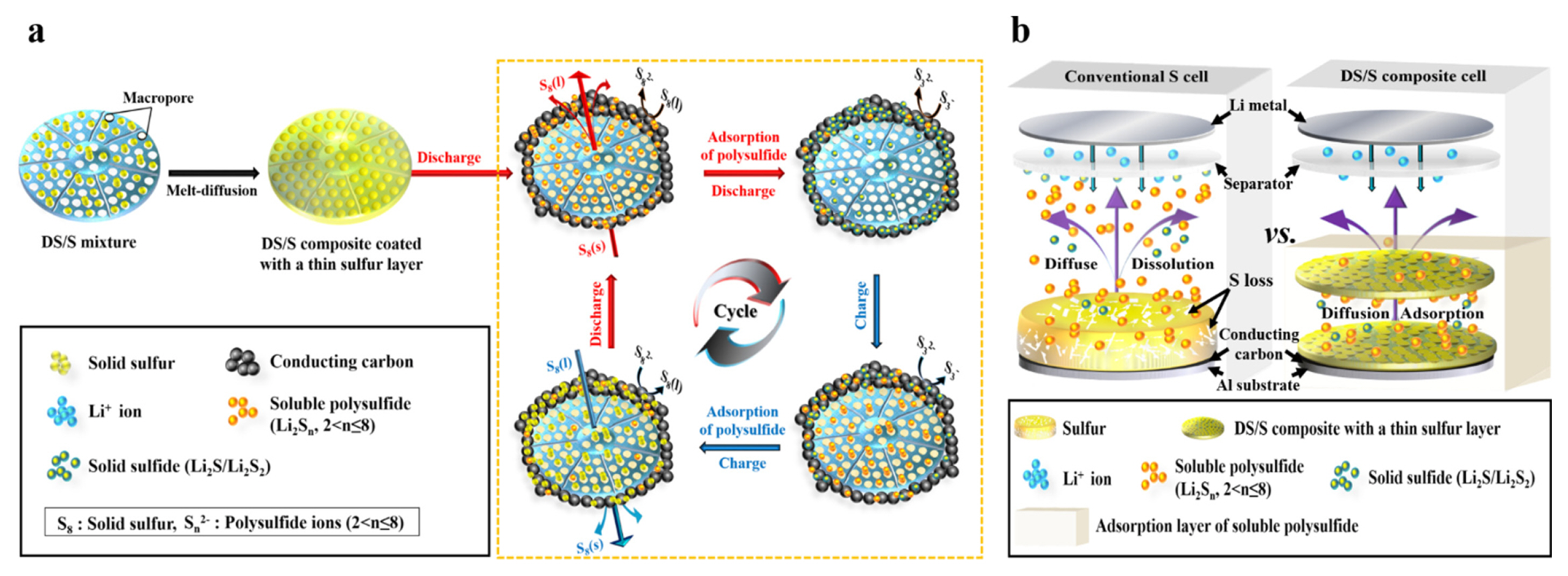
(a) Schematic representation depicting the working model of the DS/S composite during discharge-charge cycles. (b) Comparative behaviors of polysulfides during discharge: Physical adsorption within the diatomite structure of the DS/S composite cathode versus diffusion out of conventional sulfur cathodes.
Leveraging the porous architecture of diatomite, this framework not only curtails polysulfide migration from the cathode but also doubles as a sulfur reservoir within the cathode electrode, as visualized in Fig. 4b. Fig. 4a elucidates the operational mechanism of the Li-S battery, wherein sulfur contained within the porous diatomite matrix engages in electrochemical conversion reactions. This participation facilitates impressive potential and commendable cycling stability, even when sulfur particles are decoupled from the cathode’s electrical conduction pathway. Drawing from prior research, active sulfur compounds undergo dissolution in the electrolyte, forming sulfur molecules surrounded by the organic solvent [29]. These dissolved sulfur entities are then sequentially reduced to yield polysulfide ions on the exterior surface of the conductive carbon during discharge.
The discharge-charge curves for the initial and subsequent cycles of both pure sulfur and DS/S electrodes, spanning 1.8 V to 2.7 V vs. Li/Li+, at a rate of 0.1 C (where 1C = 1,675 mAh g−1), are delineated in Fig. 5a,b. Electrochemical assessments of the two cathodes exhibit analogous behaviors, both presenting nearly congruent discharge capacities at the 0.1 C rate. Notably, the DS/S cathode sustains a robust capacity, approximately 900 mAh g−1, paired with remarkable stability throughout the preliminary 10 cycles at 0.2 C. This suggests that the detached sulfur particles in the DS/S composite are dynamically engaged in electrochemical interactions.
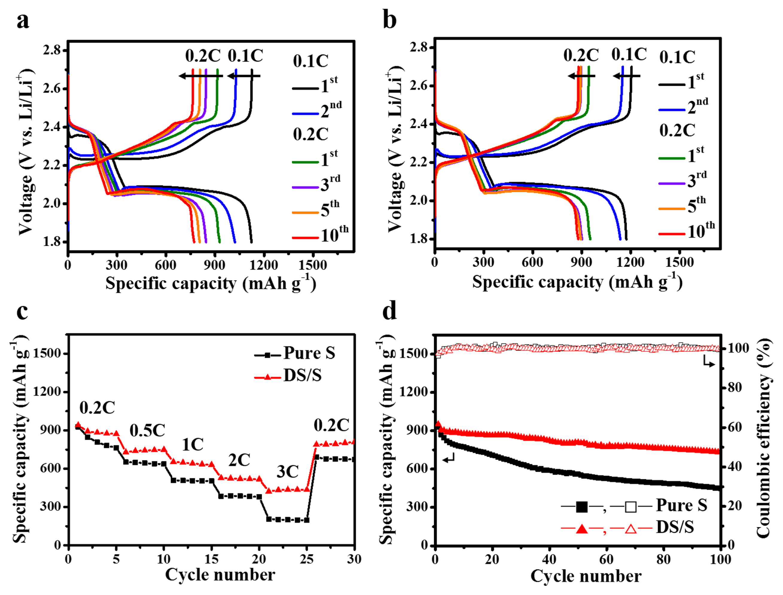
(a) Representative galvanostatic discharge/charge curves of (a) pure sulfur and (b) DS/S cells, cycled between 1.8 V and 2.7 V at room temperature The initial two cycles are conducted at 0.1 C, while subsequent cycles are at 0.2 C. (c) Rate performance comparison between the DS/S cell and the pure sulfur cell across varying C rates from 0.2 to 3 C. (d) Cycle stability of the DS/S cell over 100 cycles at 0.2 C, benchmarked against the pure sulfur cell.
Fig. 5c presents the rate performance profiles of both the pure sulfur and DS/S cells across different current densities. The DS/S setup markedly outperforms the pure sulfur in rate efficiency at every tested C rate. At elevated C rates, specifically at 3 C, the DS/S cell delivers a capacity of 422 mAh g−1, retaining 45% of its performance observed at 0.2 C. In comparison, the pure sulfur cathode registers a capacity of 205 mAh g−1, holding onto only 22% of its 0.2 C performance, as illustrated in Fig. 5c. Interestingly, upon changing the current density from 3 C to 0.2 C in the 26th cycle, the discharge capacity rebounded to approximately 92% of the value recorded in the 5th cycle, highlighting the remarkable reversibility of the DS/S cathode.
Optimal rate behaviors are expected when sulfur components are confined within a designated space, reminiscent of the hierarchical porous structure of the DS/S composite. On the other hand, diminished rate performance is likely when there’s a significant rise in mass transfer overpotential with increasing current densities. This becomes evident especially when the soluble sulfur components disperse widely, encompassing both the cathode and electrolyte areas, a phenomenon observed with the unshielded pure sulfur electrode. From this perspective, the enhanced rate capability of DS/S suggests that a large portion of the soluble polysulfides are effectively trapped within the diatomite’s porous structure, minimizing their drift toward the lithium anode. Furthermore, the presence of the DS/S composite at the cathode ensures a streamlined reaction pathway and broadened contact surface, enabling sulfur to actively engage in the electrochemical processes of the Li-S battery.
Galvanostatic cycling performance of the two cell types was assessed over 100 cycles at 0.2 C, as illustrated in Fig. 5d. Post 100 cycles, the DS/S cathode demonstrated a capacity retention of 77% (732 mAh g−1) accompanied by a capacity fade of 0.26% per cycle.
In contrast, the pure sulfur cathode retained 48% capacity (447 mAh g−1), with a decay rate of 0.73% per cycle. Remarkably, both cells consistently approached coulombic efficiencies near 100% throughout most of the cycles. Such observations underscore the superior adsorptive capacity of the hierarchically porous DS, effectively sequestering the soluble sulfur intermediates formed during cycling, a trait further corroborated by the robust rate performance in Fig. 5c. Importantly, it merits mention that, to our current understanding, the cycling stability exhibited by the pure sulfur cell surpasses that of many prior studies, suggesting that our electrochemical evaluations were meticulously executed, benefiting from an optimized cell design and assembly methodology [30–33]. Collectively, the findings robustly advocate for the DS/S composite as a straightforward yet potent strategy to elevate the electrochemical prowess of Li-S batteries, particularly in aspects of rate performance and cyclic durability.
To delve deeper into the electrochemical reactions involving the DS/S composite, we undertook ex-situ EDS analysis on the DS/S cathode at three distinct cut-off voltages: OCV, 2.06 V, and 1.8 V during the inaugural discharge cycle, as delineated in Fig. 6a. As the discharge progresses, the S-to-Si ratio (S/Si) consistently diminishes: from 0.93 at OCV, descending to 0.52 at 2.06 V, and further plummeting to 0.38 at 1.8 V vs. Li/Li+ (Fig. 6b–d). This unequivocally reveals a substantial proportion of sulfur species persisting in the diatomite at the discharge culmination. Given that all solid sulfur within the DS/S electrode engages in the electrochemical reaction during the first discharge (as demonstrated in Fig. 5a,b), the EDS findings validate the diatomite’s efficacy as a prime reservoir for soluble polysulfide ions generated amidst discharge (Fig. S2).
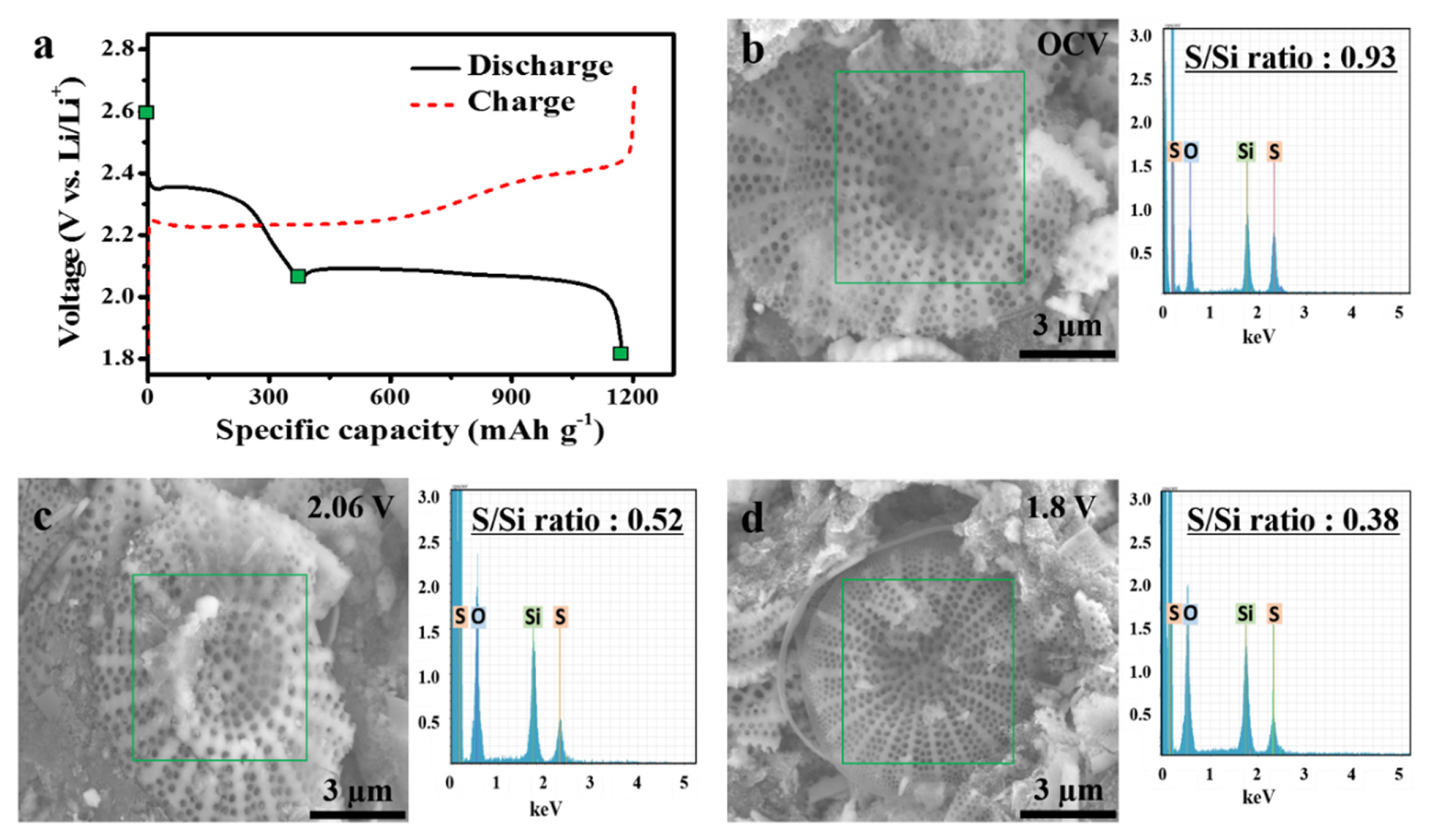
Analysis of the DS/S cell at varying cut-off voltages: (a) Initial discharge curve for different cut-off voltages. (b–d) SEM images complemented by Ex-situ EDS maps, detailing the S/Si ratio at distinct cut-off voltages: (b) OCV, (c) 2.06 V, and (d) 1.8 V.
Conventionally, for the larger scale electrode production, the roll-to-roll coating technique is favored due to its superior throughput and cost efficiency. However, this method encounters challenges in fabricating sulfur electrodes owing to the pronounced sublimation propensity of solid sulfur particles during elevated-temperature drying. The introduction of the sulfur-incorporated diatomite architecture could potentially curtail sulfur sublimation to negligible levels. To contrastively assess the sublimation rates of the two cathodes, we employed TGA analysis at 70°C under airflow over a span of 12 hours. A conventional sulfur electrode, comprising micron-scale sulfur particles as its active component, manifested a 5.0% weight decrement (Fig. 7a). In stark contrast, the DS/S electrode exhibited a mere 1.7% weight loss (Fig. 7b). This accentuates that sulfur, both within the myriad pores and upon the diatomite’s surface, is adeptly shielded, thereby effectively thwarting sulfur sublimation. Hence, the DS/S composite, rich in sulfur content, emerges as a compelling cathode contender for pragmatic Li-S battery applications. Furthermore, the DS/S composite can also diminish the leakage of soluble polysulfide ions into the electrolyte during cycling, bolstering rate capabilities at heightened C rates and ensuring robust cycling endurance. Additionally, juxtaposed against bespoke porous carbon, typically elected as a sulfur host, the readily procurable porous diatomite proffers pronounced cost and ecological advantages. Moreover, given that siliceous substrates generally exhibit diminished reactivity with sulfur compared to carbonaceous materials [34,35], sulfur utilization promises to be optimal within a siliceous host system in Li-S batteries.
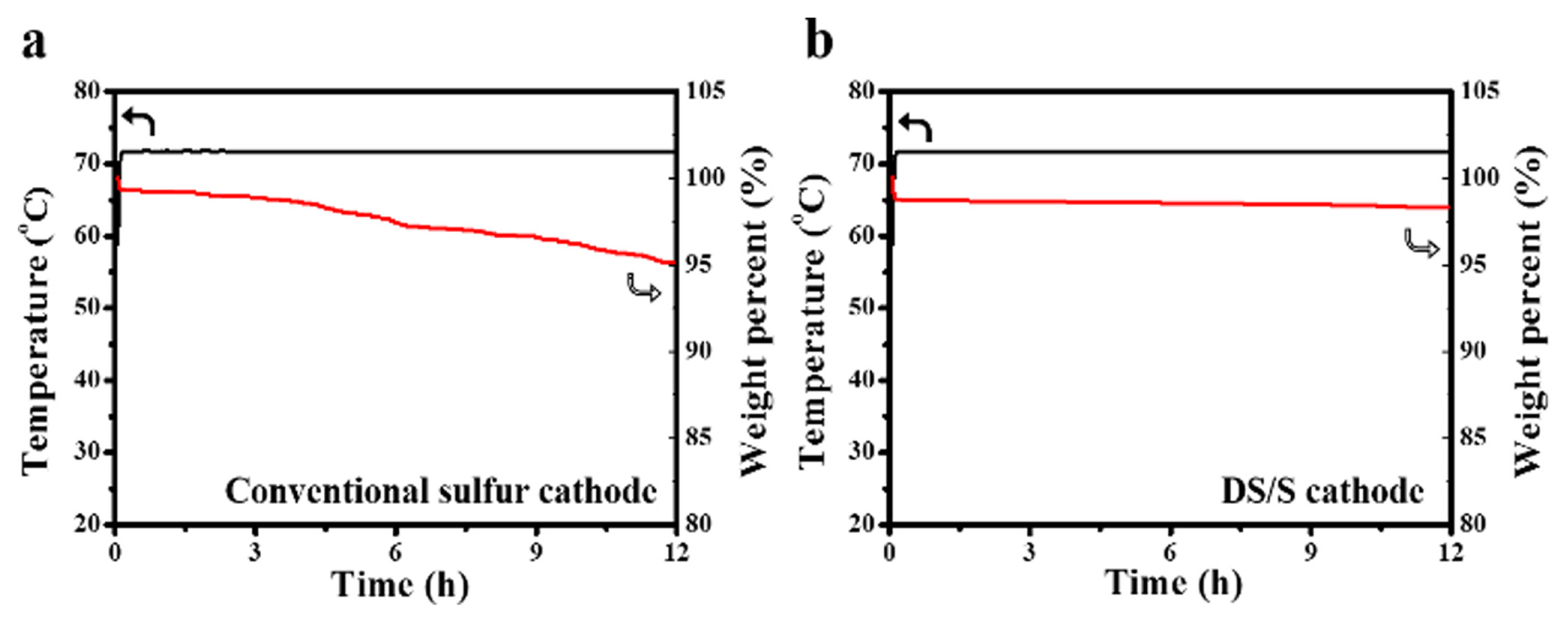
TGA analysis under an air flow at 70°C: (a) Conventional sulfur electrode and (b) DS/S electrode.
4. Conclusions
This research illuminates the efficacy of sulfur-saturated porous siliceous materials, externally encapsulated with sulfur, serving as proficient cathode materials. By utilizing naturally derived siliceous diatomite as a sulfur receptacle, SEM and nitrogen sorption assessments highlighted its intrinsic 3D interconnected hierarchical pore design, endowed with a vast pore volume. This structure is particularly conducive for containing soluble polysulfides. In comparison with a benchmark pure sulfur electrode, the DS/S configuration demonstrated superior electrochemical performance. Notably, the DS/S electrode achieved an impressive specific capacity, maintaining 732 mAh g−1 after 100 cycles and upholding 77% of its initial capacity. These metrics underscore diatomite’s capability to effectively adsorb soluble polysulfides during cycling. Furthermore, the study ascertains that a direct electrical connection between sulfur and conductive carbon is not imperative for sulfur’s electrochemical reactions. This insight broadens the spectrum of potential host materials suitable for sulfur in Li-S batteries. Based on these comprehensive findings, we are optimistic that the insights derived from this study will catalyze streamlined and scalable advancements in the development of high-performance Li-S batteries.
Supplementary Information
Acknowledgement
This work was supported by the Education and Research Promotion Program (2022) of KOREATECH and Individual Basic Science and Engineering Research Program funded by the Ministry of Education through the National Research Foundation of Korea (Grant No.: 2021R1F1A1062040 and RS-2023-00223196). The authors express their gratitude to the KBSIs at Pusan and Daegu for TEM/SEM analysis and the Cooperative Equipment Center at KOREATECH for their valuable assistance in analysis.