Aging Mechanisms of Lithium-ion Batteries
Article information
Abstract
Modern society is making numerous efforts to reduce reliance on carbon-based energy systems. A notable solution in this transition is the adoption of lithium-ion batteries (LIBs) as potent energy sources, owing to their high energy and power densities. Driven by growing environmental challenges, the application scope of LIBs has expanded from their initial prevalence in portable electronic devices to include electric vehicles (EVs) and energy storage systems (ESSs). Accordingly, LIBs must exhibit long-lasting cyclability and high energy storage capacities to facilitate prolonged device usage, thereby offering a potential alternative to conventional sources like fossil fuels. Enhancing the durability of LIBs hinges on a comprehensive understanding of the reasons behind their performance decline. Therefore, comprehending the degradation mechanism, which includes detrimental chemical and mechanical phenomena in the components of LIBs, is an essential step in resolving cycle life issues. The LIB systems presently being commercialized and developed predominantly employ graphite anode and layered oxide cathode materials. A significant portion of the degradation process in LIB systems takes place during the electrochemical reactions involving these electrodes. In this review, we explore and organize the aging mechanisms of LIBs, especially those with graphite anodes and layered oxide cathodes.
1. Introduction
Most modern technologies rely heavily on fossil fuels as an energy source. Fossil fuels have a finite supply and cause environmental problems due to global warming. LIBs have emerged as suitable energy sources for reducing carbon emissions and managing environmental issues. LIBs are energy-efficient because they operate via a controlled electrochemical reaction that relies on Li+ movement and electrons between the two electrodes. LIBs are based on Li+ flowing back and forth between two intercalation electrodes with different potentials, known as “rocking-chair” batteries. LIBs are environmentally friendly sources that exclude carbon emissions and are efficient for energy storage and conversion, so they are a promising option for future energy sources [1].
LIBs were first commercialized using a LiCoO2 (LCO) cathode, a petroleum coke anode, LiPF6 in propylene carbonate (PC) as the electrolyte, and a polyolefin separator [2]. LIBs have high gravimetric and volumetric energy densities and energy efficiency, producing smaller and lighter batteries [3,4]. Since their commercialization, LIBs have been a significant energy source for powering many portable electronic devices such as mobile phones, digital cameras, and laptops. With escalating global concerns regarding environmental issues, LIBs are expected to find broader applications, including EVs and ESSs. These devices require batteries with significantly longer lifespans than portable electronic devices because they are designed for prolonged operational durations rather than frequent replacement.
Unfortunately, prolonged operation or storage of LIBs inevitably results in a gradual decline in capacity [5,6]. This degradation process involves intricate mechanical and chemical reactions among various LIB components. The main objective of this review is to explore the aging mechanisms of LIBs, with a specific focus on cathodes and anodes currently in the commercialization stage. With regard to the anode, we delve into the aging mechanisms of graphite anodes and discuss topics such as repeated surface film formation, structural and mechanical failures, and lithium deposition. The cathode sections examine the aging phenomena observed in layered lithium transition metal oxides (LiMO2), which arise from forming a surface passivation layer, transition metal dissolution, oxygen evolution, irreversible phase transitions, and structural and mechanical failures.
2. Aging Mechanisms of Graphite Anodes
2.1 Growth of the SEI layer
LIB anodes operate at voltages below the electrochemical stability window of the electrolyte (Fig. 1) [4,7]. This results in reductive electrolyte decomposition, producing a protective layer known as the Solid Electrolyte Interphase (SEI) layer [8–10]. The ideal SEI layer selectively permits the passage of Li+ while blocking other electrolyte components and electrons, thus protecting the anodes from further reduction reactions with the electrolytes. Although the growth of the SEI layer provides stability to the LIB anode, unregulated SEI layer formation can diminish the cell performance owing to active Li+ loss and overgrown impedance. The SEI formation reaction is accompanied by the consumption of Li+, causing an irreversible capacity loss, where the number of Li+ consumed during the decomposition reaction is proportional to the specific surface area of the anode [9,11–14]. In addition, there have been reports of an impedance increase in the anodes caused by the SEI layer, which is directly correlated with the power fading of the cell [10,15,16].
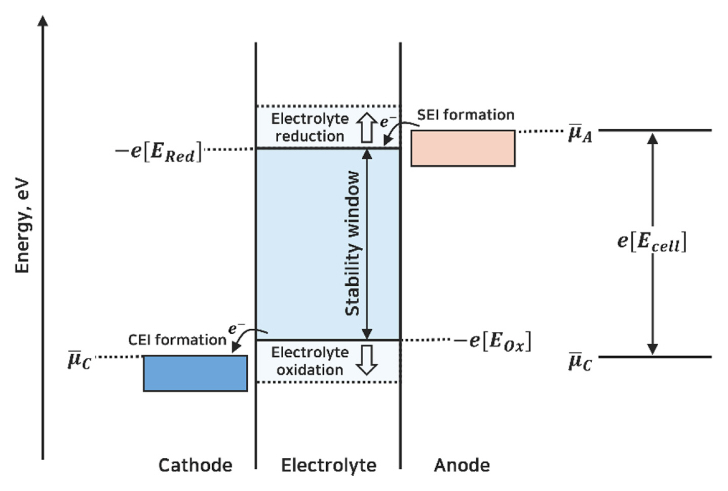
Schematic energy diagram of the electrolyte interfaces with anode and cathode. The electrochemical stability window of the electrolyte is determined by reduction potential (ERed) and oxidation potential (Eox). μ̄A and μ̄C represent the electrochemical potentials of the anode and the cathode, respectively. The open circuit voltage (Ecell) corresponds to the difference between μ̄A and μ̄C.
While the formation of the initial SEI layer saturates during the early cycles, it has been reported that the formation and modification of the SEI layer continue throughout the long-term battery cycles, leading to a gradual loss of Li+ inventory (Fig. 2) [17–20]. LIB cycled or stored at elevated temperatures exhibit accelerated capacity fading due to an increased rate of active Li+ inventory loss and radical impedance growth [21–25]. Organic compounds within the SEI layer are predominantly unstable and prone to thermal decomposition or dissolution in the electrolyte solvents, whereas inorganic compounds are relatively stable. The decomposition of the organic SEI compounds generates insoluble compounds and gaseous species. The dissolution and decomposition of organic compounds create porosity within the SEI layer, allowing the penetration of electrolytes and the formation of an additional SEI layer. The repetition of this process results in a thicker and less ion-conductive SEI layer, which is predominantly composed of inorganic species and electrolyte decomposition products, such as lithium alkoxides (LiOR), polyethylene oxides (PEO), Li2CO3, Li2O, and LiF [26–32]. Moreover, SEI layers can potentially undergo exothermic side reactions with electrolytes, leading to safety concerns, including the occurrence of self-discharge and thermal runaway [27,33,34]. Therefore, the SEI layer significantly influences the performance and safety of LIB anodes. Its structure and composition undergo intricate and dynamic changes based on factors like the electrolyte type and battery operation and storage conditions. Improving the durability of graphite anodes in LIBs entails surface modifications of graphite [35,36] and careful selection of appropriate electrolyte additives [37,38] to establish a stable SEI on the graphite.
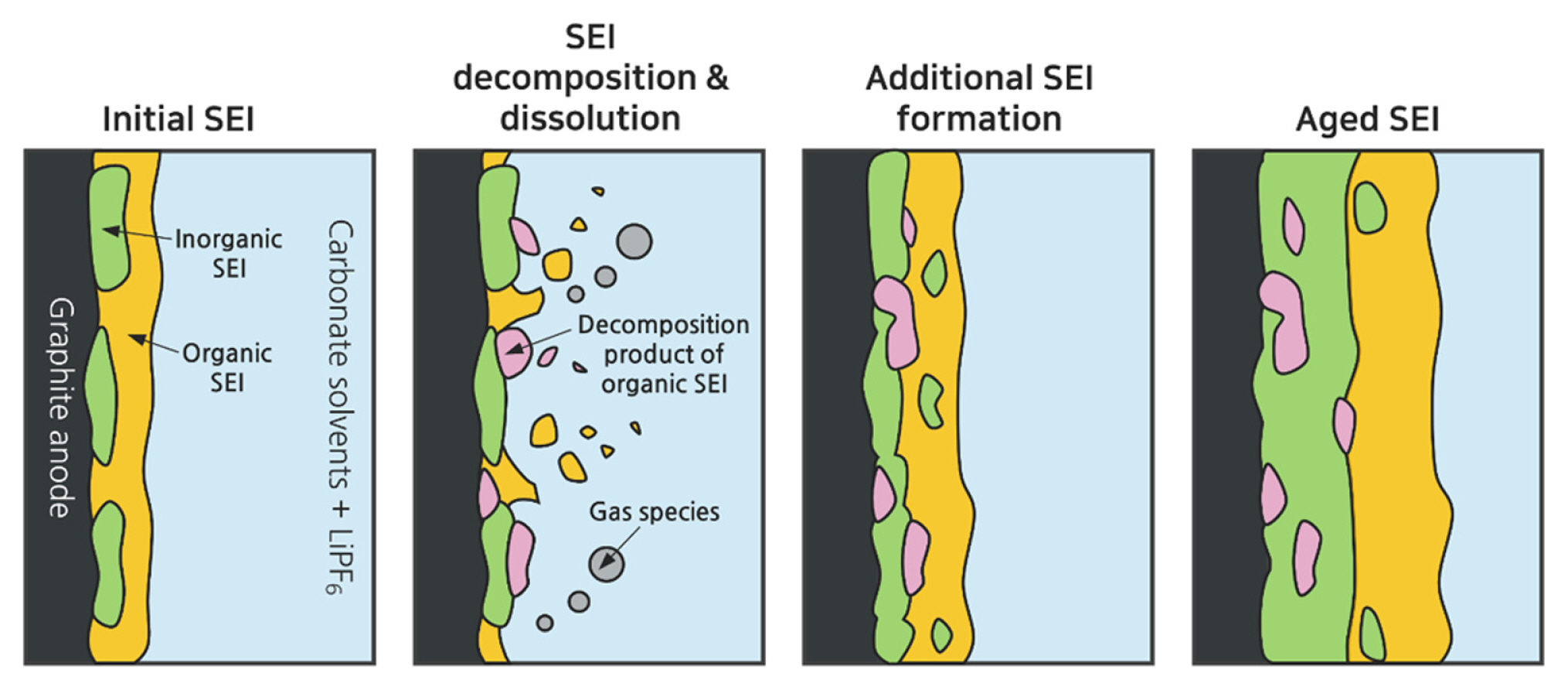
Schematic illustration depicting the process of the SEI evolution process on the anode in LIBs.
2.2 Mechanical failure
Graphite (C6) goes through several stages during the lithiation process, with two major stages: Stage 2 (LiC12) and Stage 1 (LiC6) (Fig. 3) [40–42]. A total volume expansion of 13.2% was observed when the graphite was fully lithiated (5.9% in stage 2 and 7.3% in stage 1). During repeated electrochemical cycles, cracks can develop and propagate in the graphite particles owing to the stresses generated by repeated volume expansion and contraction [42–46]. Rapid charging and discharging processes have been found to accelerate crack formation because of abrupt volume changes [43,45,46]. Exposed fresh graphite surfaces are susceptible to SEI formation reactions, contributing to cell degradation through additional Li+ consumption and increased impedance [18,46].

Many researchers have reported solvated graphite intercalation compounds (solvated GIC, Li(solv)yCn) formed through the co-intercalation of solvents into graphite and Li+ (Fig. 4(a)) [9,48–51]. Because weak van der Waals forces and π–π interactions hold together the graphene layers comprising graphite, solvents can easily co-intercalate into the interlayer spaces of graphite [39,52]. The volume expansion of the solvated GIC is greater than that of the normal GIC (LiCn) [48,52]. These co-intercalated compounds are expected to decompose and form a protective SEI layer on the graphite surface, preventing further solvent co-intercalation [48]. Ethylene carbonate (EC) is widely employed as an electrolyte solvent because of its ability to form an effective SEI layer on external graphite surfaces during the early stages of the reduction reaction (Fig. 4(c)) [9,47,48]. Vinylene carbonate (VC) is frequently used as a cosolvent to facilitate the formation of stable SEI layers [47,53]. However, when the film-forming reaction is delayed, as observed with propylene carbonate (PC), solvent co-intercalation persists, eventually resulting in the exfoliation of graphite owing to stresses caused by the expansion of the interlayer space and gas evolution from the solvent decomposition reaction (Fig. 4(b)) [9,47,53]. Graphite exfoliation disrupts graphite morphology, exposing fresh anode surfaces, thereby adversely affecting cell performance as it leads to an additional loss of Li+ inventory and an increase in impedance [54–56]. To mitigate the mechanical degradation of graphite, it’s essential to address the abrupt volume changes within the interlayer space resulting from intercalation of Li+ and solvent molecules. This can be achieved by establishing a stable SEI layer [57,58] or applying a protective coating [59] to the graphite to prevent solvent co-intercalation.
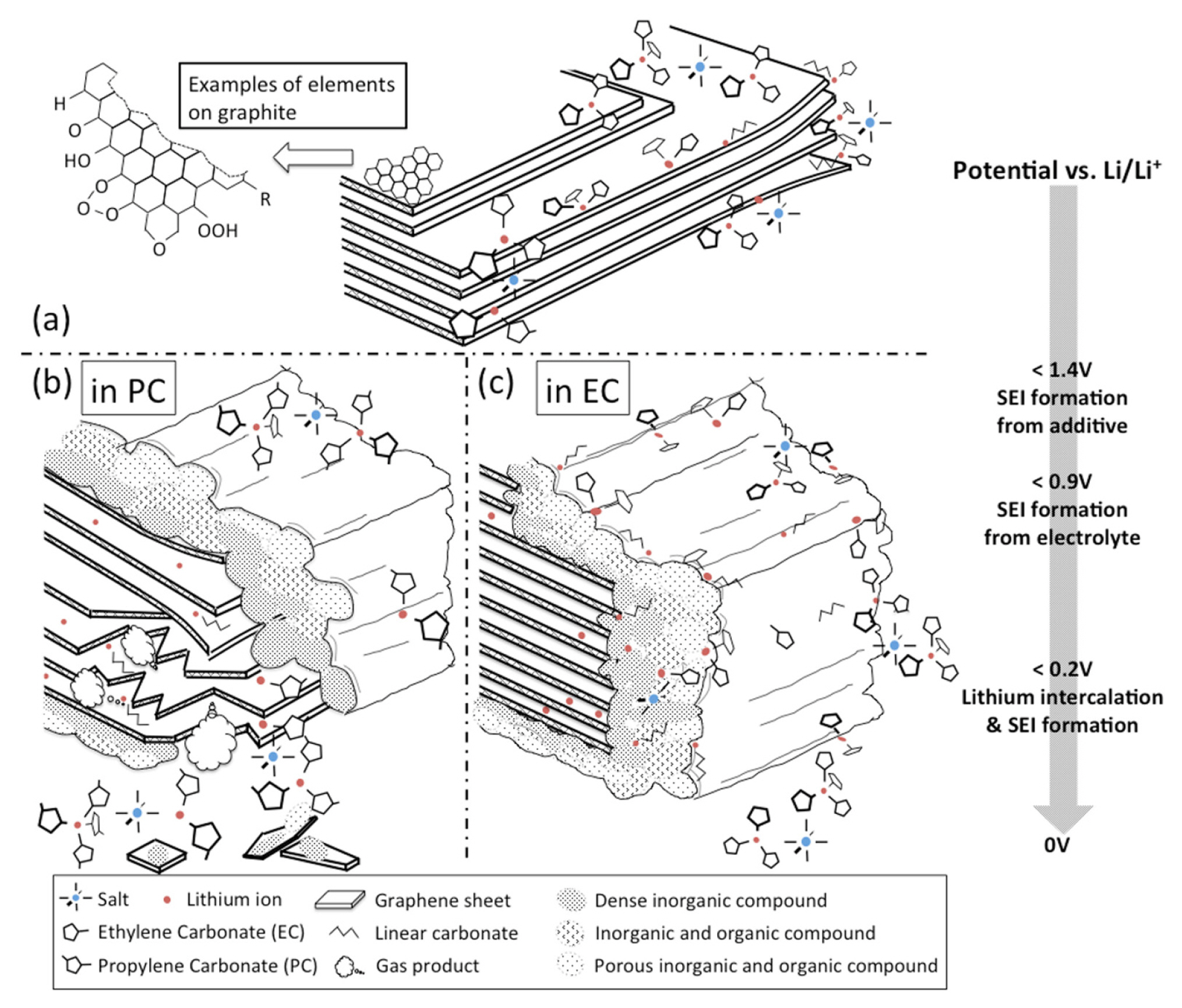
Schematic illustration of the anode SEI formation process. (a) Graphene layers surrounded by electrolyte salts and solvents above 1.4 V vs. Li/Li+. (b) Co-intercalation of PC with lithium ions into graphene layers resulting in exfoliation below 0.9 V vs. Li/Li+. (c) Stable SEI formation in EC-based electrolyte below 0.9 V vs. Li/Li+. Reprinted with permission from Ref.[47]. Copyright © 2016 Elsevier.
2.3 Lithium deposition
The durability and safety of LIB are threatened by lithium plating on the anode. Under normal charging conditions, the ideal scenario involves the insertion of Li+ into the interlayer spaces of the graphite anode. However, because of the limited kinetics of mass transport, Li+ can be reduced to metallic lithium on the anode surface [60–63]. This phenomenon becomes more pronounced under severe conditions, such as low temperatures or during fast charging [64–66]. The kinetics of the lithium plating reaction can be explained in terms of the exchange current using the Butler-Volmer equation [67,68]. The two major mechanisms of lithium plating are discussed below.
When the applied current exceeds the Li+ diffusion rate in the electrolyte, the Li+ may be depleted near the graphite surface. Such a significant polarization of the Li+ concentration can trigger lithium metal plating in a dendritic shape [67,69,70].
In cases where the diffusion of Li+ within solid materials lags behind its diffusion in the electrolyte and the insertion reaction into graphite, the sites near the surface of the graphite particles can be overcrowded with Li+ [71,72]. Thus, the intercalation rate of Li+ into graphite is drastically reduced, leading to the redirection of the remaining Li+ toward the formation of metallic lithium [73,74]. Similarly, lithium plating can also occur in a highly charged state, as most of the available sites in graphite are already occupied [61,75,76].
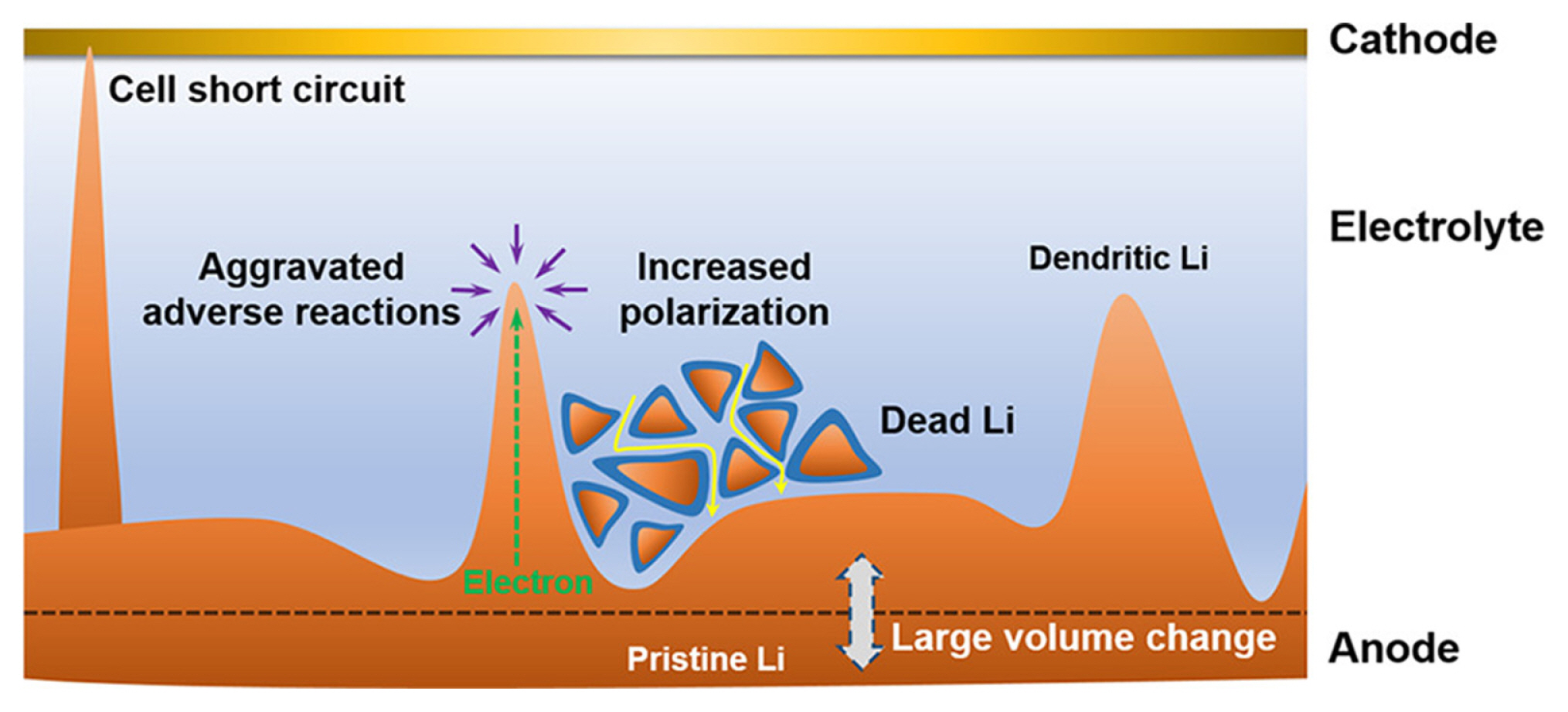
Lithium plating can directly or indirectly affect the performance and safety of LIB (Fig. 5). Because lithium plating reactions are often irreversible (e.g., dead lithium), plated lithium directly affects the active Li+ inventory [77–79]. Additionally, forming an SEI layer on the surface of the plated lithium metal results in further Li+ consumption [8,62,80]. The repetitive deposition and stripping of lithium in an inhomogeneous manner can result in the depletion of both Li+ and the electrolyte owing to the continuous formation of dead lithium and SEI [62,81]. In addition, the accumulation of plated and dead lithium clogs the porous Li+ transport pathway within the anode, thereby increasing the cell’s internal resistance [20,82,83]. Moreover, the growth of metallic dendrites can create internal short circuits within the cell, generating Ohmic heat that may induce thermal runaway and catastrophic cell failure [62,84,85]. Lithium plating is a critical concern that greatly impacts the durability and safety of LIBs. Addressing lithium plating can be achieved by controlling charging protocols [76,86] and improving kinetics within LIB cells using more concentrated electrolytes [70], or by modifying anode to reduce tortuosity [87].
3. Aging Mechanisms of Layered Oxide Cathodes
3.1 Growth of the CEI layer
A cathode electrolyte interphase (CEI) layer is a film that develops on the cathode surface through oxidative electrolyte decomposition [88–93]. Unlike graphite, layered lithium transition metal oxide cathodes exhibit resistance to solvent co-intercalation owing to strong Coulomb and covalent bonds maintaining lattices [94]. Nevertheless, numerous studies have identified the CEI layer and reported its detrimental effects on the available Li+ inventory and cell impedance [93,95–99]. Like the SEI layer, the CEI layer comprises both inorganic and organic components [93,100,101]. The development of the CEI layer is influenced by three major factors, which are discussed below.
Influence of pre-existing surface species The surfaces of layered oxide cathodes often contain lithium carbonate (Li2CO3), which is produced by the reaction between residual lithium (Li2O) and carbon dioxide (CO2) [102–105]. When Li2CO3 comes into contact with electrolytes like LiPF6, it undergoes spontaneous reactions, generating species such as LiF and POxFy as well as gaseous byproducts such as O2 and CO2 (Fig. 6) [106–110].
The reaction with cathode lattices The LIB cathodes operate at a higher voltage than the electrochemical stability window of the electrolytes, enabling direct reactions between the cathode lattices and the electrolytes (Fig. 1). This results in the reduction of transition metals within the cathodes and the oxidation of the electrolytes, producing Li2CO3, LiF, and LiOR [107–109,111,112].
Interaction between SEI and CEI There is a strong correlation between the surface products of the cathode and the anode. The components in the CEI and SEI layers are often soluble in electrolyte solvents and can be transferred onto the surface of counter electrodes (Fig. 6) [93,113–115].

Schematic illustration depicting the process of CEI layer formation on the cathode and the interaction between SEI and CEI.
Battery operation under high voltage and elevated temperatures expedites these processes, forming a thicker CEI layer, contributing to the increased consumption of Li+ and higher cell impedance [116–119]. Similar to the SEI layer, the creation of a stable CEI layer is crucial to safeguard against further electrolyte decomposition on the cathode surface. This can be done by incorporating electrolyte additives capable of producing a stable and thin protective layer [120,121], or by applying a protective coating on the cathode surface [122].
3.2 Transition metal dissolution
Divalent transition metals (M (II), M = Ni, Co, or Mn) in lithium transition metal oxides tend to dissolve in the electrolyte during electrochemical reactions within the cell [124–132]. The dissolution of manganese ions in the spinel lithium manganese oxide (LiMn2O4) is particularly remarkable because the disproportionation reaction readily produces Mn (II) ions [124–127,133]. Although not as severe as that of lithium manganese spinel, other transition metals, such as nickel and cobalt ions in layered oxide cathodes, demonstrate a propensity to dissolve in electrolytes (Fig. 7) [123,129,130,132,134]. In layered oxide cathodes, the formation of M (II) is primarily observed on the surface and is driven by the following reactions.
The dissolution of transition metals results in the loss of electrochemically active redox centers, directly affecting the capacities of LIB [127,130,131]. Moreover, the dissolved transition metals in the solution can have an adverse impact composition and morphology of both the CEI and SEI layers through the dissolution, migration, and deposition (DMD) process [128,130,131,134,135]. Transition metal dissolution becomes more pronounced when the cell is cycled at a high cutoff voltage and temperature [129,130, 133,136]. Preventing transition metal dissolution is crucial for protecting both the cathode and anode. The application of a cathode coating has been shown to effectively inhibit transition metal dissolution [137,138], while the incorporation of transition metal-capturing additives can help prevent DMD [139].
3.3 Oxygen evolution reaction
Generating gaseous species such as CO2, CO, and O2 within the cells poses a significant challenge in LIBs. A small amount of CO2 gas can be released through the decomposition reaction between Li2CO3 on the cathode surface and the electrolyte [140,141]. However, the predominant source of gaseous species that evolve in cells is the oxygen evolution reaction (OER). In LCO, oxygen actively participates in charge compensation via OER because the Co3+/4+ redox couple uses electrons in the t2g orbital, significantly overlapping with the oxygen 2p orbital [142–146]. Although oxygen in nickel-based layered oxide cathodes is typically considered safer from anionic redox reactions, as the Ni3+/4+ redox couple uses eg electrons and oxygen activation, the gas release has been observed in highly charged states [142,147,148]. Ni-rich layered oxide cathodes, particularly those exceeding 80% nickel in the transition metal composition, exhibit an enhanced release of oxygen gas at a high state of charge (SoC) (Fig. 8(a–d)) [140,149,150]. The release of oxygen gas from the partially delithiated layered oxide cathodes can be accelerated at elevated temperatures, and a higher nickel content increases the likelihood of thermal oxygen release (Fig. 8(e)) [140,151,152]. Activated or released lattice oxygen can undergo reactions with alkyl carbonate electrolytes, producing additional gaseous byproducts such as CO2 and CO (Fig. 8(a–e)) [141,153,154].

(a) Cell voltage vs. specific capacity plot of half cells employing NCMs having different nickel contents. The total moles of evolved gases in the On-line Electrochemical Mass Spectrometry (OEMS) cell, normalized by the cathode active material BET area, is presented for (b) O2, (c) CO2 and (d) CO. Reprinted with permission from Ref. [140]. Copyright © 2017 ECS. (e) The total amounts of generated O2 (black), CO (blue), and CO2 (dark blue) in the OEMS cell resulting from OER and subsequent electrolyte decomposition, as well as the amounts of evolved CO2 due to EC hydrolysis (pink). Reprinted with permission from Ref. [141]. Copyright © 2018 ECS.
The OER can compromise the cell performance by causing irreversible modifications to the cathode surface structure and degrading the integrity of the CEI layer. Structural densification driven by oxygen loss and transition metal dissolution at the surface, along with the absence of Li+ in the charged state, leads to irreversible changes in the surface structure of the cathode (discussed in Section 3.4). Furthermore, the released oxygen can chemically and mechanically affect CEI layer components’ composition, homogeneity, and morphology [155]. High temperatures, fast charging, and charging batteries to a high SoC promote massive gas release, posing significant safety hazards, such as self-heating and thermal runaway [156–160]. The OER poses a critical vulnerability for layered oxide cathodes, leading to rapid cell aging and safety hazards. The application of cathode coatings [161,162] and the introduction of doping elements [163,164] have demonstrated their effectiveness in mitigating the OER and, consequently, improving the cell’s capacity retention.
3.4 Irreversible phase transition
Transition metals and oxygen are the fundamental elements that support the layered oxide frame and play a critical role in maintaining the structural integrity of layered oxide cathodes. Therefore, any loss or displacement of such elements can lead to irreversible structural damage, resulting in fading of the electrochemical performance of the cathode (Fig. 9) [165–168]. During the charging process, lithium vacancies are created, providing a pathway for transition-metal migration to the lithium sites. The migration of transition metals induces a phase transition from a layered structure (LiMO2, R-3m) to a spinel phase (LiM2O4 or M3O4, Fd-3m) and rock salt phases (MO, Fm3m) with lower oxygen stoichiometry [169–171].
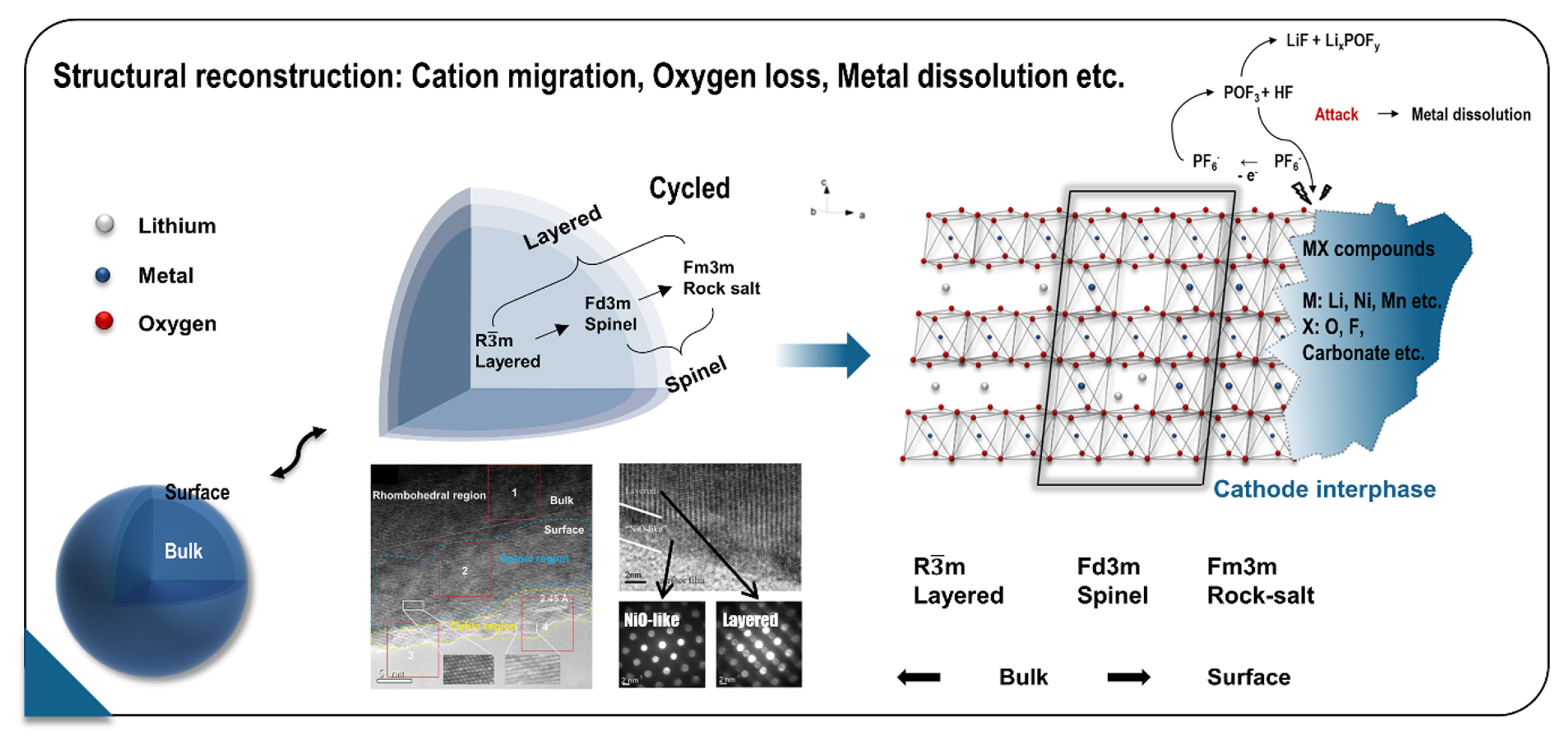
Schematic illustration of surface deterioration mechanism observed in cathode materials. The surface structure of high-energy cathode materials can be degraded by the collective impact of cation migration, oxygen loss, and metal dissolution. Reprinted with permission from Ref. [165]. Copyright © 2020 Wiley.
Such irreversible phase transitions are observed in thermal abuse experiments, where partially delithiated layered oxide cathodes are exposed to high temperatures exceeding 500°C. During migration, transition metal ions in the octahedral sites migrate to vacant octahedral lithium sites through adjacent intermediate tetrahedral lithium sites (Oh-Td-Oh, tetrahedral site hop) [172–174]. The migration behavior and the resulting structural phases vary depending on the specific transition metal. Cation mixing is prominent because of the similarities in size between Li+ and Ni2+ and the thermodynamic advantages in structure and magnetic properties [175,176]. Ni2+ prefers to occupy lithium octahedral sites during migration, driven by their inherent instability at lithium tetrahedral sites. In contrast, cobalt ions are metastable at lithium tetrahedral sites and reside in a tetrahedral environment. In contrast, manganese ions display high stability and remain at their original transition metal octahedral sites [157,174,177,178]. Therefore, nickel ions predominantly migrate to the lithium octahedral sites in nickel, cobalt, and manganese ternary layered oxide systems, whereas lithium is pushed to the tetrahedral sites, producing a LiM2O4-type spinel [157,179]. In Ni-rich layered oxide cathodes, the continual migration of nickel towards the lithium octahedral sites results in the formation of rock salt structures. In contrast, cathodes containing higher cobalt contents prefer to form M3O4-type spinel structures, where cobalt ions migrate toward the lithium tetrahedral sites [180–182]. Note that there are two types of spinel phases: LiM2O4 with a 3D lithium channel and M3O4 without a lithium pathway.
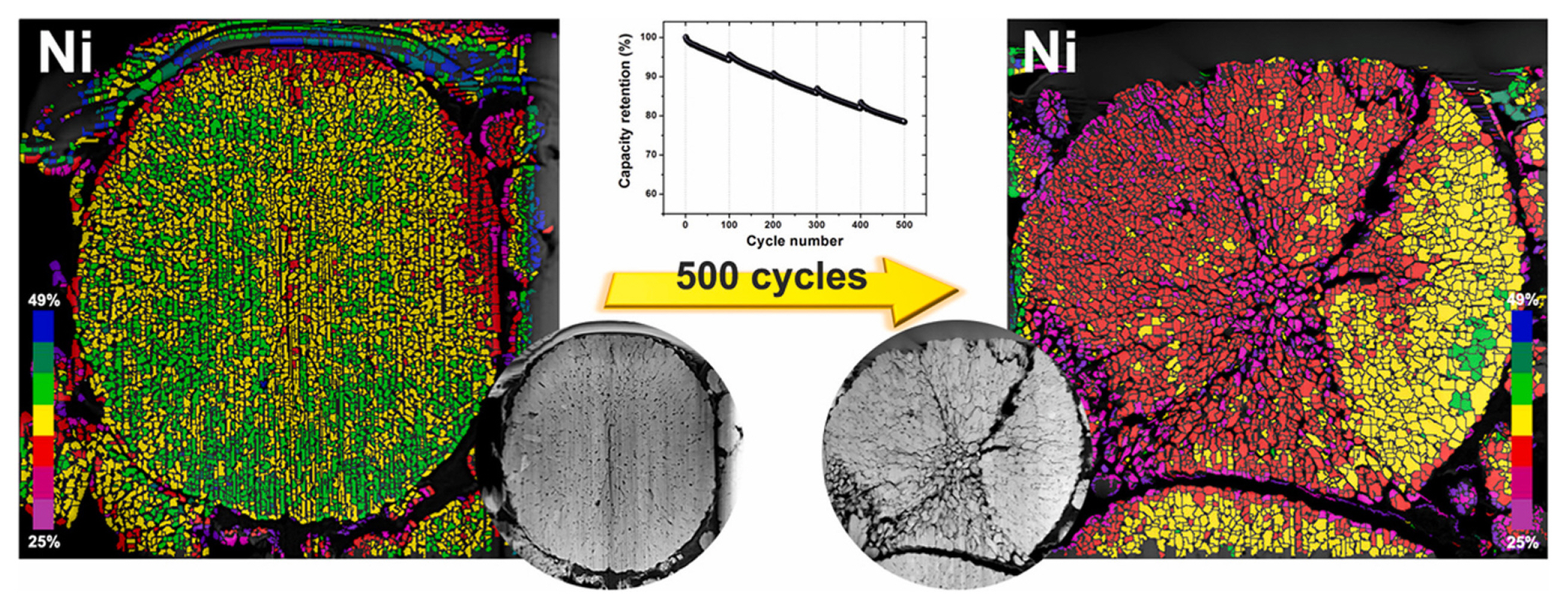
Under normal operating conditions, the surfaces of cycled particles are particularly prone to irreversible structural degradation owing to the significant occurrence of transition metal dissolution and oxygen gas release [166,183–185]. As inferred from the migration behavior of transition metals, the NiO rock salt phase is commonly observed on the surface of aged Ni-rich layered oxide cathodes [186–188], whereas the surface structure of LCO often consists of the Co3O4 spinel phase [182,183,189]. The formation of either the NiO rock salt or the Co3O4 spinel phase on the cathode surface impedes the insertion and extraction of Li+, increasing the overall cell impedance [190–192]. The migration of transition metals to the lithium slab can also occur within the bulk of the particles, although to a lesser extent than on the surface or under thermal conditions. While adequate cation mixing has the potential to enhance the lithium transport kinetics and mitigate lattice collapse and oxygen repulsion during deep delithiation, excessive cation mixing can be detrimental because the migrated transition metals obstruct the Li+ paths [193,194]. Cation mixing of Ni2+ and Li+ can occur even during their synthesis, owing to the ease with which nickel occupies the lithium octahedral sites [195–197]. During operation, cation mixing exhibits occasional reversibility [198,199] but tends to intensify progressively over long-term cycles, disrupting atomic ordering within the cathode materials and reducing the solid-state diffusion rate of Li+, thereby impairing battery performance [198,200,201]. Irreversible phase transitions in the bulk structure result from the migration of transition metals into lithium sites, which can be prevented through doping strategies [202]. In contrast, irreversible phase transitions in the surface structure are closely linked to transition metal dissolution and the OER, and these transitions have been successfully mitigated through coating methods [203–205].
3.5 Mechanical failure
The crystal structures of pristine layered oxide cathodes, such as LCO, LiNiO2 (LNO), and LiNix-CoyMn1-x-yO2 (NCM), with the general formula Lix-MO2, have a rhombohedral R-3m space group (alpha-NaFeO2 structure), in which the octahedral interstitial sites of the O3 close-packed oxygen framework are cross-filled with Li+ and transition metal (M) cations [206,207]. During the electrochemical delithiation, the layered oxide cathodes undergo reversible phase transitions between the related layered structures (O3, O1, and H1–3 for LCO [163,208] and H1, H2, and H3 for LNO [209,210]) and monoclinic structures. The phase transitions that result in minimal changes to the host structure, including the insulator-metal transitions (O3(I) to O3(II)) in LCO [211,212], LiFePO4 (LFP) to FePO4 [213,214], and spinel LiTi2O4 (LTO) to Ti2O4 [206,215], can be considered relatively mild phase transitions. In contrast, the phase transitions of layered structures at a high SoC, which are accompanied by rapid changes in the host structure symmetry and lattice parameters (from O3 to H1–3 to O1 in LCO [163,216] and from H2 to H3 in LNO [217,218]), may cause mechanical failure of the electrode particles after several charge/discharge cycles.
In the NCM, the phase transition from H2 to H3 is known to be suppressed for nickel contents below 80% but becomes activated for nickel content exceeding 80%, causing a sharp anisotropic shrinkage in the c-direction as illustrated in Fig. 10(a) [1,197,217]. Severe shape and volume changes in the host structure and lattice mismatch induced by phase separation during transitions between two distinct phases can generate significant stresses, resulting in the cracking of the electrode particles (Fig. 10(b)) [219–222]. Particle cracking can lead to the fragmentation or delamination of particles, resulting in inhomogeneous lithiation/delithiation reactions [223,224] and exposure of fresh particle surfaces to further surface deterioration reactions with the electrolytes [142,217]. The mechanical failure of layered oxide cathodes is intricately linked to the anisotropic volume changes experienced by the cathode unit cell during phase transitions. These detrimental phase transitions can be delayed through the implementation of doping strategies involving various dopant elements [225,226]. Moreover, research has shown that the particle’s integrity can be reinforced by utilizing single crystal structures [227] or designing particles with a concentration gradient [228,229].
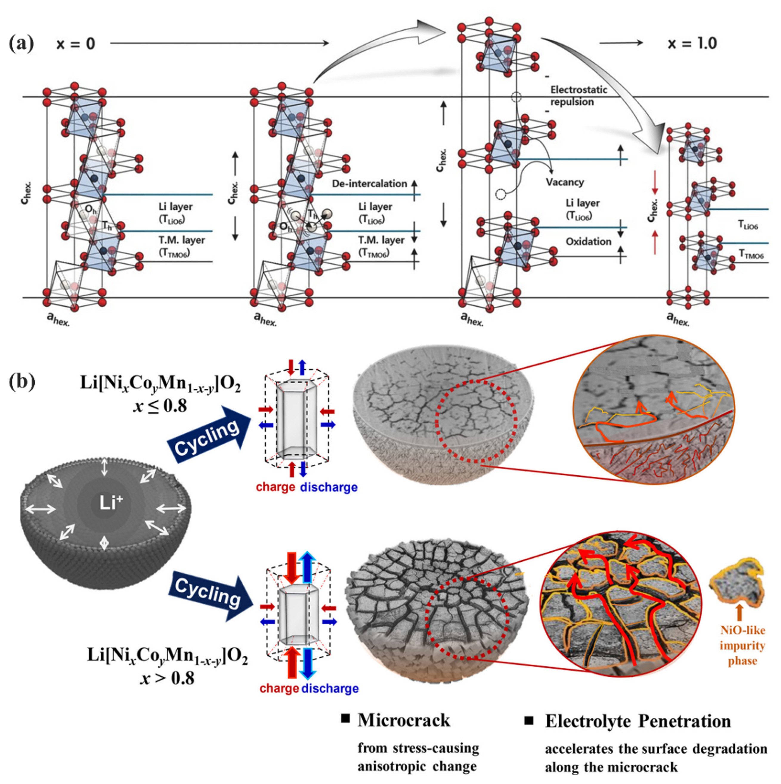
(a) Schematic illustration of the structural behavior of the Ni-rich layered oxide cathodes at different SoC. Reprinted with permission from Ref. [206]. Copyright © 2018 Wiley. (b) Schematic illustration of the mechanical degradation of Ni-rich layered oxide cathodes caused by repetitive abrupt anisotropic volume changes. Reprinted with permission from Ref. [217]. Copyright © 2018 ACS.
4. Conclusions
Understanding the intricate aging mechanisms of LIBs is the cornerstone for developing durable and long-lasting LIBs. This review briefly explores the chemical and mechanical degradation of graphite anodes and layered oxide cathodes in LIBs (Fig. 11). In graphite anodes, repeated formation of the SEI layer leads to a substantial loss of Li+ inventory and increased cell impedance. The expansion of the interlayer space in graphite during lithiation, which is further exacerbated by the co-intercalation of solvent molecules, can result in cracks and delamination, thereby exposing fresh graphite to further SEI formation. Lithium plating poses a significant concern as it depletes Li+ and electrolytes, increases impedance, and potentially triggers thermal runaway owing to internal short circuits. Researchers have demonstrated the effectiveness of surface modification of graphite and the addition of electrolyte additives can both tackle issues concerning the CEI layer and mechanical failures. Additionally, addressing lithium plating requires careful consideration of kinetics, such as controlling charging protocols, utilizing higher concentration electrolytes, and modifying the graphite electrode to reduce tortuosity.

Schematic illustration of main aging mechanisms of commercial LIBs.
In layered transition metal oxide cathodes, the growth of the CEI layer consumes Li+ and contributes to an increase in cell impedance. The dissolution of transition metals impairs cell performance by diminishing the redox center and compromising the anode through DMD. Gas generation from the OER can lead to performance degradation and pose significant safety concerns. Irreversible surface phase transitions, accompanied by the dissolution or dislocation of transition metals and oxygen loss, increase the overall cell impedance because deactivated rock salt and spinel phases are formed on the surface. Throughout long-term cycling, cation mixing between the transition metals and Li+ tends to increase, thereby hindering the transport of Li+ and consequently impairing battery performance. In a highly charged state, the bulk phase transition of layered oxide cathodes is associated with the abrupt decrease of the c-lattice and volume of the unit cell, leading to particle cracking and subsequent exposure of fresh particles to further surface degradation. The challenges associated with the CEI layer can be addressed by incorporating additives or applying a protective coating. The degradation linked to transition metal dissolution, OER, and surface irreversible transitions are intricately intertwined and can be effectively managed through extensive coating and doping strategies. Irreversible phase transitions within the bulk, resulting from cation mixing, and mechanical failures due to volume changes of layered oxide cathode materials can be mitigated through doping strategies that impede transition metal migration and detrimental phase transitions. Additionally, careful design of cathode particles can further prevent mechanical failures.
Further research is necessary to effectively prevent the aging of LIBs and to develop innovative materials, electrode designs, and cell configurations capable of overcoming these challenges. This will facilitate the development of durable and high-performance LIBs to meet the future demands of the battery-of-things (BoT) society.
Acknowledgment
This work was supported by the Technology Innovation Program (No. 20024249, ‘Development of mass manufacturing technology for high performance lithium iron phosphate composites’) funded By the Ministry of Trade, Industry & Energy (MOTIE, Korea). This work was also supported by the National Research Foundation of Korea (NRF) grant funded by the Korea government (MSIT) (No. NRF-2022R1A2B5B02002624).