Synergistically Enhanced Oxygen Evolution Catalysis with Surface Modified Halloysite Nanotube
Article information
Abstract
Synergistically increased oxygen evolution reaction (OER) of manganese oxide (MnO2) catalyst is introduced with surface-modified halloysite nanotube (Fe3O4-HNTs) structure. The flake shaped MnO2 catalyst is attached on the nanotube template (Fe3O4-HNTs) by series of wet chemical and hydrothermal method. The strong interaction between MnO2 and Fe3O4-HNTs maximized active surface area and inter-connectivity for festinate charge transfer reaction for OER. The synergistical effect between Fe3O4 layer and MnO2 catalyst enhance the Mn3+/Mn4+ ratio by partial replacement of Mn ions with Fe. The relatively increased Mn3+/Mn4+ ratio on MnO2@FHNTs induced σ* orbital (eg) occupation close to single electron, improving the OER performances. The MnO2@FHNTs catalyst exhibited the reduced overpotential of 0.42 V (E vs. RHE) at 10 mA/cm2 and Tafel slope of (99 mV/dec), compared with that of MnO2 with unmodified HNTs (0.65 V, 219 mV/dec) and pristine MnO2 (0.53 V, 205 mV/dec). The present study provides simple and innovative method to fabricate nano fiberized OER catalyst for a broad application of energy conversion and storage systems.
1. Introduction
Increasing demand for clean and sustainable energy has stimulated research on energy conversion and storage systems, including fuel cells, water splitting, alkaline electrolysis, and metal-air batteries. The catalytic materials for these systems play a key role in the development of high-performance and durable devices at an affordable price [1,2]. The electrode materials for such energy devices should deliver high catalytic activity as well as great conductivity for fast reaction kinetics. Oxygen electrode catalyst, in which oxygen evolution reaction (OER) takes place, has been regarded as the main challenge due to the sluggish kinetics of the 4-electron involved reaction pathway. Noble metal-based OER catalysts, such as IrO2, RuO2, and RhO2 have been adopted for effective electrode materials for commercialized systems [3–5]. Their low overpotential and high electrical conductivity showed great OER performances, however, the high cost and scarcity of noble metal still hinder their practical application [6,7].
The non-precious metal or metal oxide-based OER catalyst is attracting attention as an alternative solution in OER electrode design [8–10]. MnO2 has been studied and regarded as a feasible candidate in the development of transition metal-based OER catalysts [11,12]. The manganese oxide catalysts exhibited great redox stability both in acid and alkaline electrolytes compared with that of other transition or noble metal-based catalysts [13–15]. These electrode materials have the potential to be an effective OER electrode catalyst for various energy devices, however, further optimization is required to overcome the relatively higher overpotential and low electronic conductivity [16–18].
Recent studies on manganese oxide catalysts were mainly underway to increase their active surface area and inter-connectivity by tailoring their electrode scaffold design with various preparation methods, including porous or fiberized structure [19,20]. For example, the electrospinning method could also be a possible way to fabricate MnO2 based nanofibers with increased active surface area and inter-connectivity [21–24]. The mesoporous structure is also studied for an electrode material in water electrolysis and supercapacitor, increasing electrode surface as well as structural stability [25,26]. The structure modified MnO2 catalysts improved catalytic performances by successfully maximizing active surface areas, however, these pristine materials require high cost and complicated fabrication processes, which limit their practical commercialization.
The naturally abundant halloysite nanotubes (HNTs), therefore, has recently introduced as an innovative template to fabricate nano fiberized catalyst on many applications. The nano-sized tabular structure of the HNTs template has a high length to diameter ratio and an open end with hallow morphology, which maximizes the catalytically active surface area as well as gas diffusion channel [27,28]. The surface properties of HNTs could be manipulated by substituting their hydroxyl ions into organic or inorganic materials to overcome the inherently low electronic conductivity and poor adhesion of nano catalysts [29,30]. Compared with the pristine nanofiber fabrication processes the HNTs template could deliver an easy preparation method at a low cost.
In this work, we fabricated the surface decorated Fe3O4-HNTs (FHNTs) with a MnO2 nano catalyst (MnO2@FHNTs). The Fe3O4 coated HNTs template (FHNTs) is designed to increase the electronic conductivity as well as adhesion between the nano tube template and MnO2 catalyst. The MnO2@FHNTs nano catalyst was fabricated by the reduction-precipitation method and following the hydrothermal process. The morphologies and chemical composition of MnO2@FHNTs nano catalyst were investigated before and after surface modification. The synergistically enhanced OER activity between Fe3O4 layer and surface MnO2 catalyst was also investigated to understand their improved reaction kinetics. The electrochemical performances of oxygen evolution reaction were analyzed by rotating disk electrode (RDE) method with alkaline electrolyte condition.
2. Experimental
2.1. Materials synthesis
Halloysite nanotubes (HNTs), sodium sulfite (Na2-SO3), sodium hydroxide (NaOH), Ammonium persulfate ((NH4)S2O8), Iron (III) chloride hexahydrate (FeCl3.6H2O), and potassium permanganate (KMnO4) were attained from Sigma Aldrich, Germany.
In the synthesis method, 0.5 g of HNTs was added to 50 ml of DI water and the suspension was thoroughly ultrasonicated and stirred for 1 hr. Then FeCl3.6H2O solution (2%) was added to the mixture and then the resultant mixture was reflexed for 30 min. It is followed by the addition of Na2SO3 (0.3%) into the mixture. That results in the wine-red color of the mixture solution. After the addition of 30 mL of NaOH, the mixture solution turned to black colored precipitate of the Fe3O4 loaded HNTs (FHNTs) and an external magnet separated the FHNTs powder. The FHNTs were washed meticulously with DI water, methanol, and ethanol to eliminate residues.
The attained powder was dried in an oven at 50°C for 24 hr and followed by the grinding by mortar and pestle for further usage. The F-HNTs were decorated by MnO2 nanoflakes by following the same procedure in our previous [30]. To summarize the procedure, 2 g of FHNTs was added to the 50 mL of DI water. The solution mixture was ultrasonicated and refluxed for 1 hr. The subsequent solution mixture was added by KMnO4 (3.6 g) and ((NH4)S2O8) (4.2 g) under constant refluxing. The attained solution mixture was dispensed in a 250 ml Teflon-lined stainless-steel autoclave and set aside at 105°C for 24 hr. An external magnet separated the gained bluish-black colored precipitate of F-HNTs-MnO2. The as-prepared powder material was washed with DI water and dried at 50°C for 24 hr and then the powder was grinded by mortar and pestle and used for characterization and electrochemical analysis. The schematic illustration of MnO2@FHNTs synthesis processes is presented in Fig. S1.
2.2. Materials characterization and electrochemical analysis
The crystalline purity of the HNTs and F-HNTs-MnO2 was characterized by the XRD (Rigaku, smart LAB.) analysis in a range of 5°~90° with 2°/min scanning speed. The morphological properties of all the prepared samples were investigated by SEM (TES-CAN, Vega3) and HR-TEM (JEOL, JEM-2100F), respectively. The surface chemical properties of synthesized materials were analyzed by using TEM/EDS and X-ray photoelectron spectroscopy (Thermo Fisher scientific, K-Alpha+). The electrochemical properties were characterized by a rotating disk electrode system (RRDE-3A, ALS), with a glassy carbon disk electrode as a working electrode, Pt wire, and 1.0 M NaOH saturated Hg/HgO as a counter and reference electrode, respectively. Alkaline electrolyte of 0.1 M KOH (Sigma Aldrich, 99.99%) solution was N2 purged for 1h before electrochemical measurement. The catalyst suspension ink was prepared by mixing catalyst materials (2 mg), conductive carbon (6 mg, Vulcan XC72R), 5 wt.% Nafion solution (70 uL, Sigma Aldrich) and isopropyl alcohol (1 mL), respectively. The suspension ink was ultrasonicated for 30 min before drop coating (6 uL) on the glass carbon electrode. Cyclic voltammetry (CV) with different scanning speeds (5~100 mV/s) was conducted to determine the double layer capacitance (CDL) between electrode catalyst and electrolyte. The OER performance of prepared materials was characterized in O2 saturated 0.1 M KOH electrolyte solution at a scanning rate of 10 mV/s with a rotating speed of 1600 rpm.
3. Results and Discussion
3.1. Characterization of catalyst
The surface-modified HNTs catalyst before and after the fabrication processes are illustrated in Fig. 1. The pure HNTs (HNTs ref.) templates showed the average diameter of ~160 nm and various lengths ranging from 100 nm ~ 2 um after series of wet chemical and hydrothermal synthesis processes. This result suggests that the HNTs template could be a feasible candidate in developing fiberized 3-D catalysts using conventional wet chemical and hydrothermal methods without any structural deformation. The Fe3O4 layer was attached to the HNTs surface after the wet chemical precipitation process, delivering ferromagnetic properties on FHNTs (Fig. 1(d,g)). The surface abundant hydroxyl ions on the HNTs template enabled the strong interaction between HNTs and Fe3O4. The magnetized HNTs (FHNTs) are covered by nano-flake MnO2 catalyst after the following hydrothermal synthesis process (Fig. 1(e,h)). The nano-flake-shaped MnO2 particles first attached to the surface magnetized FHNTs structure and crystalized with reducing temperature. This surface property of FHNTs improved the structural inter-connectivity between MnO2 and FHNTs template. The strong interaction between MnO2 and FHNTs constrained the agglomeration of MnO2 during the hydrothermal process, compared with the pristine MnO2 powder catalyst prepared without the FHNTs template.

Structural and chemical analysis of MnO2@FHNTs. (a) Schematic illustration of MnO2@FHNTs fabrication process, (b) TEM/EDS mapping result of MnO2@FHNTs, and (c–h) surface morphological differences characterized by FE-SEM and HR-TEM.
The surface chemical properties of MnO2@FHNTs catalyst were exhibited in Fig. 1b and Fig. 2 after TEM/EDS and XPS analysis, respectively. The EDS mapping results before and after each fabrication steps are characterized in Fig. S2 and Fig. 1b, respectively. The results clearly showed that the partially covered Fe3O4 on HNTs template is attracting nanoflake MnO2 catalyst, increasing catalytically active surface area.
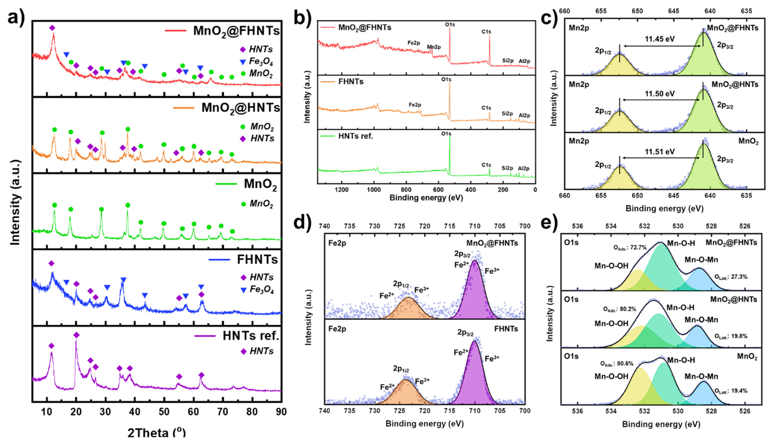
HR-XRD and X-ray photoelectron spectroscopy (XPS) results of prepared catalyst samples. (a) HR-XRD spectra of all prepared samples. (b) XPS spectra of MnO2@FHNTs, FHNTs, and HNTs ref., (c) Mn2p spectra of MnO2@FHNTs, MnO2@HNTs, and MnO2, (d) Fe2p spectra of MnO2@FHNTs and FHNTs, (e) O1s spectra of MnO2@FHNTs, MnO2@HNTs, and MnO2, respectively.
The phase characterization of all the prepared samples was also illustrated in Fig. 2a, after HR-XRD analysis. The HNTs ref. the sample showed typical crystalline planes as per the (JCPDS 29-1487) [31]. The FHNTs exhibited additional Fe3O4 peaks after the wet-chemical precipitation process. The MnO2@FHNTs showed a typical crystalline plane (001) of HNTs ref. such as (2θ=12.50°). Subsequently, the surface modifications significantly decreased the intensity and sharpness of the HNTs ref. peaks at a higher diffraction angle. This observation probably originated from the thick coating of the Fe3O4 and 3-D MnO2 nano-flake on MnO2@FHNTs as exhibited by SEM and TEM images in Fig. 1. The slightly clear peak intensity of partially modified MnO2@HNTs and FHNTs samples also supports this result. The typical tetragonal phase of α-type MnO2 (JCPDS 44-0141) was detected on the MnO2@FHNTs, MnO2@HNTs, and powder MnO2, which is synthesized under the same hydrothermal process. Compared with various MnO2 polymorphs, α-MnO2 tends to have the higher OER activity [32]. The result obtained here indicates that the hydrothermal condition for MnO2 nano-flake formation is optimized in the development of MnO2 based OER catalyst.
The XPS analysis results of MnO2@FHNTs catalysts were also shown in Fig. 2 for further investigation. All the elements of HNTs, Fe3O4, and MnO2 appeared in the survey spectra of MnO2@FHNTs, which correspond to 74.47, 100.40, 527.50, 642.59, and 711.06 eV for Al2p, Si2p, O1s, Mn2p, and Fe2p, respectively (Fig. 2b). This observation also indicates that the surface-modified MnO2@FHNTs catalyst was successfully obtained under series of fabrication processes without impurities or secondary phases. Fig. 2c shows the high-resolution spectra of Mn2p for MnO2@FHNTs, MnO2@HNTs, and MnO2, which include the specific binding energy of 654.57 and 642.64 eV. The binding energy difference (~11.45 eV) between two separated peaks indicates the Mn4+ in the MnO2 phase [33]. The high-resolut ion Fe2p spectra of MnO2@FHNTs and MnO2@HNTs were also analyzed and illustrated in Fig. 2d. The binding energy difference of ~12.93 eV is attributed to the presence of Fe3O4, which confirms that the surface Fe3O4 layer on HTNs template [34]. The O1s peaks could be deconvoluted into oxygen ions in an oxide lattice structure (Mn-O) and adsorbed oxygen ions (Mn-OH and Mn-O-OH) on the surface of catalytic materials, respectively [33]. Fig. 2e exhibits the area fraction of deconvoluted O1s peaks of MnO2@FHNTs, MnO2@HNTs, and MnO2 catalysts, respectively. The deconvolution result of MnO2@FHNTs sample indicates 27.3% of lattice oxygen (Mn-O) and 72.7% of absorbed oxygen ions (Mn-OH and Mn-O-OH). The high concentration of surface adsorbed oxygen ions (Mn-OH and Mn-OOH) is widely regarded as a prerequisite for OER, providing enough starting or intermediate ions in the catalysis process [35,36]. The relative ratio of adsorbed oxygen ions for MnO2@HNTs (OAds.: 80.2%) and MnO2 (OAds.: 80.6%) were higher than that of MnO2@FHNTs (OAds.: 72.2%). This observation is probably originated from the surface covering Fe3O4 layer in MnO2@FHNTs sample. The Fe3O4 layer on HNTs template is believed to increase the relative amount of surface lattice oxygen, while reducing the pristine hydroxyl ions on pure HNTs surface. The overall results obtained here demonstrate that the potential application of MnO2@FHNTs catalyst as an OER catalytic material with superior activity.
3.2. Electrochemical properties of catalyst
The OER activity of MnO2@FHNTs, MnO2@HNTs, MnO2, FHNTs, and HNTs ref. catalysts are summarized in Fig. 3. The OER polarization curve shows further enhanced OER activity after doping MnO2 on the surface of the FHNTs structure. The MnO2@FHNTs showed the lowest onset potential and highest current density, compared with that of other samples (Fig. 3a). The overpotential at the current density of 10 mA is widely adopted for evaluating the performance of OER catalyst materials, such as alkaline electrolysis and water splitting. The MnO2@FHNTs catalyst exhibited an overpotential of 0.46 V (V vs. RHE) at 10 mA current density, which is higher than pristine bulk MnO2 catalyst materials [32]. Fig. 3a inset shows the magnified OER characteristics near onset potential region. The FHNTs exhibited a slightly increased current density than the raw HNTs template (HNTs ref.), while the onset potential for OER remained similar. This result implies that Fe3O4 coating on HNTs only improved the electronic conductivity of the HNTs template without tailoring its catalytic activity. The MnO2@HNTs sample without Fe3O4 layer was also prepared and characterized to understand the effect of Fe3O4 layer on the HNTs template. The MnO2@HNTs exhibited higher overpotential and lower current density then MnO2@FHNTs. The pristine powder MnO2 catalyst showed even lower overpotential and higher current density then that of MnO2@HNTs. This result indicates that the surface Fe3O4 coated HNTs (FHNTs) could improve the electrochemical properties of MnO2 catalyst. The catalytic properties of MnO2 based OER catalysts were further investigated by calculating their overpotential and mass-specific current density. Fig. 3c exhibits the overpotential and mass-specific current density of the prepared MnO2 based catalysts deposited on the FHNTs and HNTs template. The MnO2@FHNTs showed the lowest overpotential of 0.42 V (V vs. RHE) at 5 mA/cm2 current density, which is much lower than 0.53 V and 0.65 V for pristine MnO2 and MnO2@HNTs samples, respectively. The mass-specific current density of MnO2@FHNTs catalyst at 1.6 V (V vs. RHE) exhibited 13.30 A/cm2, while pristine MnO2 and MnO2@HNTs only recorded similar results of 4.52 A/cm2 and 4.36 A/cm2. The sluggish overpotential and the lower specific current density of MnO2@HNTs (0.65 V, 4.36 A/cm2) than pristine MnO2 (0.53 V, 4.52 A) are probably originated from the additional raw HNTs template, which delivers inherently no catalytic activity as well as low electronic conductivity.
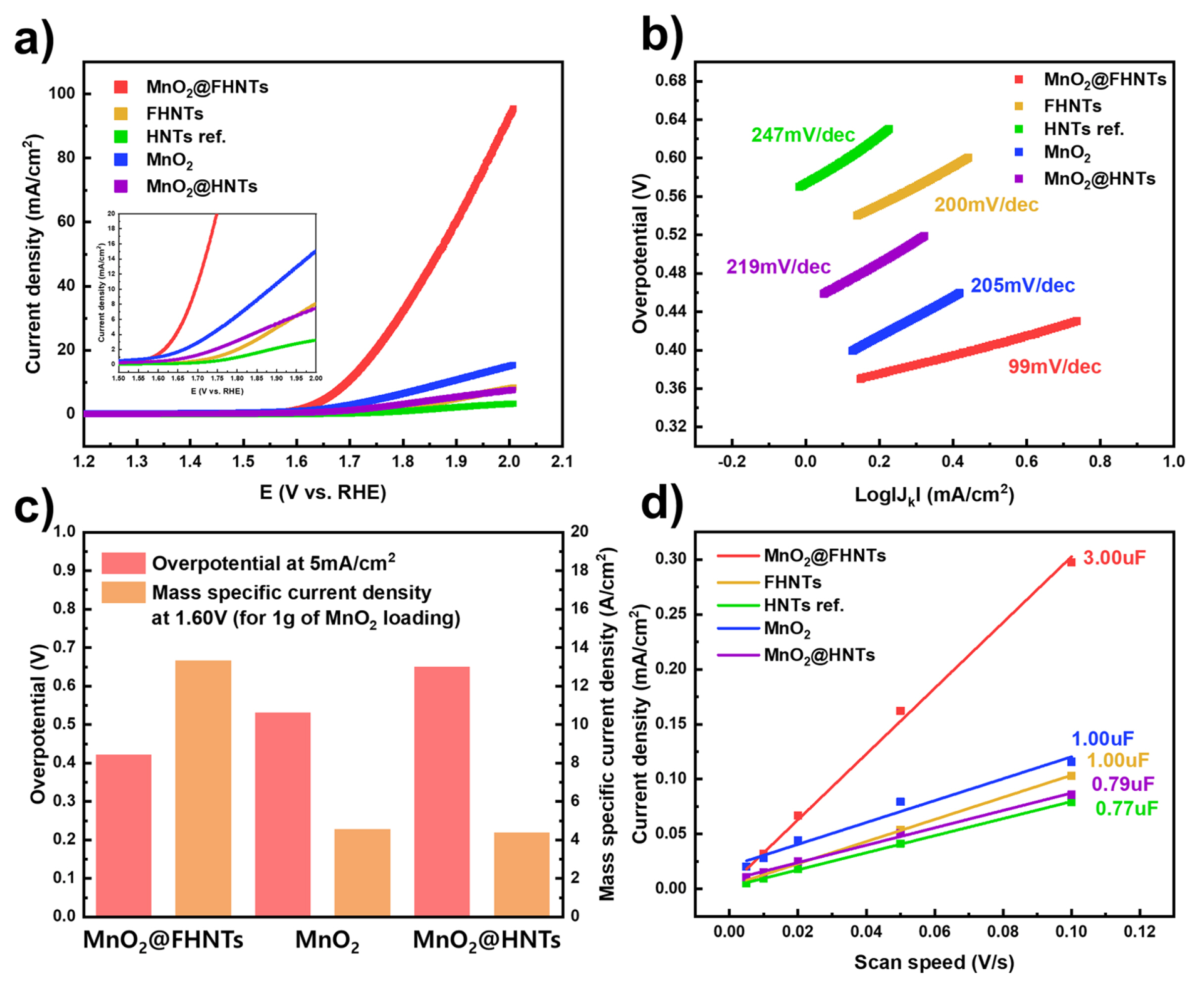
Electrochemical properties of HNTs based catalysts. (a) OER polarization curve under 0.1 M KOH electrolyte, (b) Tafel plots of OER catalysis, and (c) double-layer capacitance of prepared sample.
Fig. 3b shows the Tafel plot of the prepared catalyst samples obtained from the LSV polarization curve. The Tafel slope of MnO2@FHNTs, MnO2@HNTs, and HNTs ref. was 99 mV/dec, 219 mV/dec, and 247 mV/dec, respectively. The pristine MnO2 and FHNTs recorded 205 mV/dec and 200 mV/dec, which is almost overlapping that of MnO2@HNTs. The lowest Tafel slope of MnO2@FHNTs confirms that the reaction kinetics of OER near onset potential region is drastically improved by nano-flake MnO2 with FHNTs, indicating that the energy required for activation of OER is probably reduced after MnO2 deposition on the FHNTs template. This observation also implies that a synergistic effect could exist between MnO2 and Fe3O4 coating and FHNTs could be a favorable template for nano-sized MnO2 catalysts. The catalytic activity of various MnO2 based OER catalysts were listed in Table S1 for comparison.
Fig. 3d exhibits the double-layer capacitance of the prepared sample, which is consistent with an electrochemically active surface area of each catalytic material. The MnO2@FHNTs sample showed a double-layer capacitance of 3.00 uF, which is 3 times higher value than FHNTs (1.00 uF) and HNTs ref. (0.77 uF). The pristine MnO2 and MnO2@HNTs sample exhibited the similar double-layer capacitance of 1.00 and 0.79 uF, respectively. This tendency could be explained by the morphological properties of HNTs catalysts in Fig. 1, which show the increasing active surface area of MnO2@FHNTs as serial doping of Fe3O4 and MnO2. The addition of FHNTs template restrained the agglomeration of MnO2 catalyst under synthesis process, maximizing the catalytically active surface area. Also, the sluggish electronic conductivity of raw HNTs is believed to reduce the electrochemically active surface area of the reference MnO2@HNTs sample. The full CV curves at different scanning speeds for calculating double-layer capacitance and the related calculating processes were summarized in Fig. S3.
3.3. Effect of Fe3O4 layer on OER activity
The above electrochemical analysis results suggest that the MnO2@FHNTs catalyst could be a feasible candidate for enhancing OER activity. Understanding the fundamental catalytic activity of MnO2@FHNTs is vital in the development of further improved OER catalysts. The oxygen evolution reaction steps on the surface of MnO2 are illustrated in Fig. 4a [4,37–39]. The series of OER steps on the MnO2 oxide catalyst involves a 4-electron transfer pathway with adsorption and desorption of hydroxyl (OH−) ions. The increased electronic conductivity of MnO2@FHNTs catalyst by additional Fe3O4 coating on HNTs template, therefore, is believed to improve the OER activity as discussed in the previous studies of MnO2 based electrochemical catalyst materials with transition metal oxide [26,40,41]. Furthermore, the nano fiberized FHNTs structure not only increased the active surface area by attracting nano-flack MnO2 catalysts but also improved their inter-connectivity like other fiberized catalytic materials.
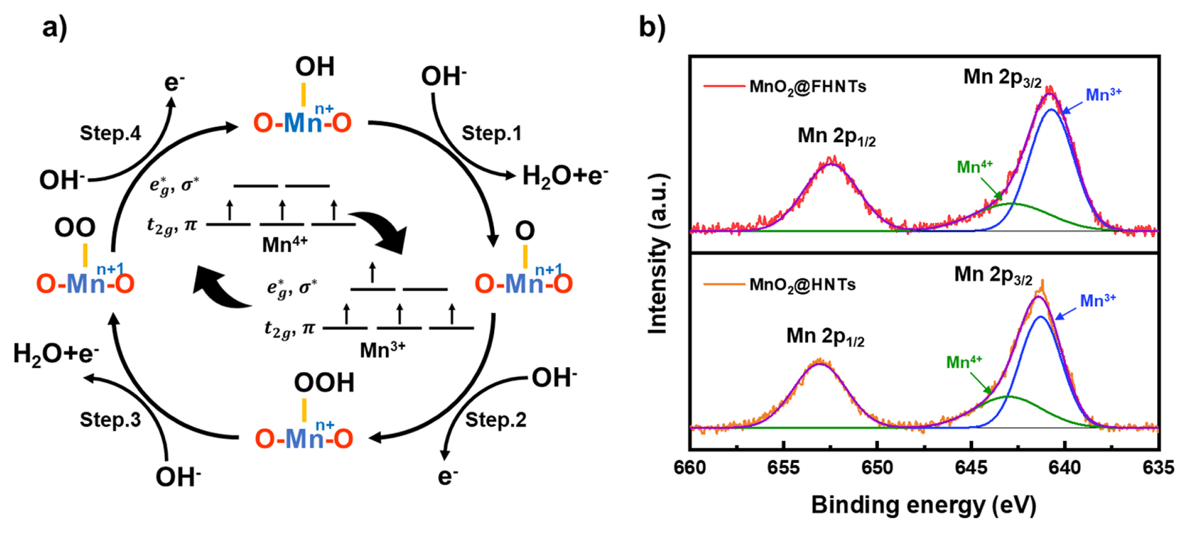
(a) Oxygen reduction reaction steps on the MnO2 based catalyst and related electronic configuration of Mn ions. (b) XPS spectra of Mn2p on MnO2@FHNTs and MnO2@HNTs.
Fig. 4b shows the XPS spectra of Mn2p on MnO2@FHNTs and MnO2@HNTs catalyst after deconvolution. The Mn2p1/2 and Mn2p3/2 peaks of MnO2@FHNTs catalyst were slightly shifted to the lower binding energy, compared with that of MnO2@HNTs catalyst. This observation suggests that the average oxidation state of Mn ions was partially decreased with the surface coating of Fe3O4 on the HNTs template. The Mn2p3/2 peak can be deconvoluted into two peaks of 641.1 and 642.2 eV, which represent Mn3+ and Mn4+ species [42]. The ratio of Mn3+/Mn4+ ions was revealed to 2.58 and 2.20 for MnO2@FHNTs and MnO2@HNTs catalyst, respectively (Table 1). The higher Mn3+/Mn4+ ratio of MnO2@FHNTs catalyst was probably originated from ionic interdiffusion between MnO2 and Fe3O4 interface, in which Mn4+ ions were partially replaced by Fe3+ ions under synthesis process, resulting in the formation of additional oxygen vacancy in the hydrothermal synthesis process [43,44]. This observation is also supported by MnO2-Fe3O4 composite catalyst materials prepared by various methods [45,46].
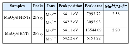
Mn ions ratio of MnO2@FHNTs and MnO2@HNTs catalyst from XPS results
The rate-determining step (RDS) of OER for MnO2 catalyst was generally proposed as the O-O double bond formation and the proton extraction from OOH− group, which attribute to the step 2 and step 3 reaction in Fig. 4a [47–49]. The electronic configuration of Mn3+ and Mn4+ species is illustrated in Fig. 4a inset [38,50]. The higher Mn3+/Mn4+ ratio of MnO2@FHNTs is probably facilitated the OER process by manipulating the σ* orbital (eg) occupation close to single electron, therefore reducing the required free energy difference for the formation of O-O bond on Mn ions [47–49,51]. The higher Mn3+/Mn4+ ratio of MnO2@FHNTs catalyst driven from synergistic effect between Fe3O4 layer, therefore, is believed to improve its OER performance than pristine MnO2 and MnO2@HNTs catalyst.
4. Conclusions
In summary, the hollow nano fiberized MnO2@FHNTs catalyst was synthesized by series of wet precipitation processes and hydrothermal method using earth-abundant HNTs template. The Fe3O4 layer on HNTs template were attracted the surface nano flack MnO2 catalyst increasing electronic conductivity as well as electrochemical active surface area for OER. The Fe3O4 layer increased Mn3+/Mn4+ ratio of MnO2 catalyst, causing synergistic effect by single electron occupation σ* orbital. The LSV curve exhibited that overpotential of MnO2@FHNTs at 5 mA current density shifted negatively by 110 mV and 230 mV compared with that of pristine MnO2 and MnO2@HNTs catalyst. The reduced Tafel slope of MnO2@FHNTs also showed the improved reaction kinetics with the surface Fe3O4 layer on HNTs structure. The results suggest that the MnO2@FHNTs could be a promising nano template in the development of OER catalytic materials. The MnO2@FHNTs catalyst is believed to be utilized for various energy conversion and storage systems, such as alkaline electrolysis and metal-air batteries.
Acknowledgments
This work was supported by the Korea Institute of Energy Technology Evaluation and Planning (KETEP) grant funded by the Korea government (MOTIE) (G032542411), and by Incheon National University (International Cooperative) Research Grant in 2018.
Supporting Information
Schematic illustration of materials synthesis process, TEM/EDS images, Cyclic voltammetry curves, and comparison table for OER performances