1. Introduction
Drastic climate change and limited fossil fuel reserves have driven interest in the development of sustainable and renewable energy technologies, such as an efficient energy storage system (ESS). Supercapacitors (SCs), as an ESS, have attracted attention for their high power capacity and long-term cycle stability [1ŌĆō3], owing to their simple energy storage mechanism at the interface between the electrode and electrolyte [4ŌĆō6]. SCs are mainly classified into two types, depending on the energy storage mode: pseudocapacitors (PCs) store energy via a fast and reversible Faradaic redox reaction at the electrode surface [7], whereas electrical double-layer capacitors (EDLCs) are based on electrostatic ion interactions at the electrodeŌĆō electrolyte interface.
Owing to the difference in the energy storage mechanisms, the electrode material of SCs is an important component that af fect s the electrochemical performance of the ESS. Unlike PCs, which are made of metal oxides, EDLCs are usually made of carbon materials, which are low cost, environmentally friendly, non-toxic [8], and stable against explosion after repeated charging and discharging reactions, making them suitable to be used as electrodes. Therefore, many studies using carbon materials such as graphene nanoplatelets (GnPs) [9,10], carbon nanotubes (CNTs) [11ŌĆō14], graphene oxide [15ŌĆō17], and carbon nanofibers [18ŌĆō20] have been reported.
Among the electrode materials used in EDLCs, CNTs, which form mesopores, allow ions to readily diffuse into the active surface of the electrode material. Their advantages can help lower the equivalent series resistance and increase power. CNTs can be classified as single-walled carbon nanotubes or multi-walled carbon nanotubes (MWCNTs), both of which have been investigated as potential electrode materials [21,22]. Yanshyna et al. reported that MWCNTs with high porosity and conductivity can effectively store ions, which contributes to their adaptability and resistance to aqueous media in EDLCs [4,23]. In addition, Daraghmeh et al. reported that composite electrode materials using MWCNTs have excellent capacitance and low internal resistance, thereby increasing the specific capacitance of capacitors. To study capacitors with improved specific capacitance using MWCNT, it is necessary to select suitable electrode materials with high specific areas and appropriate pore sizes to improve the specific capacitance of EDLCs [24,25].
Graphene has exhibited great potential as an efficient electrochemical capacitor owing to its large specific surface area (SSA) and high conductivity [26]. Jeon et al. reported the edge chemistry between miniature graphene and a molecular wedge [27]. The poly(phosphoric acid)/phosphorous pentoxide (PPA/ P2O5) medium was previously optimized for the ŌĆ£directŌĆØ functionalization of carbon-based nanomaterials [28ŌĆō30]. In this study, we prepared edge-carboxylated graphitic nanoplate (CGnP)@MWCNT hybrid nanomaterials, with covalent bonds between CGnP and MWCNT, using edge chemistry to develop excellent electrode materials, which have both the advantages of MWCNTs and graphene. Hybrid nanomaterials synthesized by optimal ratio of MWCNT to CGnP has exhibited improved electrochemical performance and excellent cycle stability.
2. Experimental
2.1 Preparation of CGnP
CGnP was prepared from graphite powder using a ball-milling method as previously reported [31,32]. Pristine graphite (5 g), dry ice (100 g), and stainless-steel balls (500 g) were placed in a stainless-steel container, which was sealed and fixed in a planetary ball milling machine, followed by agitation at 500 rpm. After 48 h, the resulting material was treated with a 1 M HCl aqueous solution to completely remove metallic impurities. Finally, the product was freeze-dried at ŌłÆ120┬░C under reduced pressure (0.5 mmHg) for 48 h to yield a dark black powder (5.68 g).
2.2 Preparation of CGnP@MWCNT_X
CGnP (1.5 g), MWCNT (0.3 g), PPA (83% P2O5 assay: 40 g), and P2O5 (10 g) were mixed and stirred at 130? for 72 h in a 250-mL resin flask equipped with a high-torque mechanical stirrer under a dry nitrogen purge. Then, the product was Soxhlet-extracted with water for three days to remove PPA and P2O5. Finally, the final product was freeze-dried at ŌłÆ120┬░C under reduced pressure (0.5 mmHg) for 48 h to yield a dark black powder (CGnP@MWCNT_5:1; 1.77 g). Additionally, other samples with different ratios of CCnP to MWCNT (CCGnP@MWCNT_1:1 and CGnP@MWCNT_1:5) were also prepared under the same conditions.
2.3 Characterization of CGnP@MWCNT
Morphological observat ions of CGnP, CGnP@MWCNT_5:1, CGnP@MWCNT_1:1, and CGnP@MWCNT_1:5 were performed using fieldemission scanning electron microscopy (FE-SEM; Hitachi, S-4800, Japan). High-resolution transmission electron microscopy (HR-TEM) was performed on a JEOL JEM-2100F (Cs) microscope operating at 200 kV. X-ray diffraction (XRD) patterns were recorded using a Rigaku D/MAZX 2500V/PC with Cu-K╬▒ radiation (35 kV, 20 mA, ╬╗ = 1.5418 ├ģ). The SSAs were determined by applying the BrunauerŌĆōEmmettŌĆōTeller (BET) equation to isotherms recorded at ŌłÆ196┬░C using a BELSORP-mini II analyzer (Mictrotrac BEL, USA). Chemical structures such as functional groups were examined using Fourier-transform infrared (FT-IR) spectroscopy (Spectrum Two, PerkinElmer, USA).
2.4 Electrochemical measurement of the electrode material
Galvanostatic charge-discharge (GCD), cyclic voltammetry, and electrochemical impedance spectroscopy (EIS) were carried out using a battery testing system (BCS-815, Bio-logic, Germany) in 6 M KOH aqueous solution as the electrolyte. The electrode material was prepared by mixing the active material (80 wt.%), binder (polyvinylidene fluoride, 10 wt.%), and Super-P (10 wt.%), as a conductive carbon material, using N-methyl-2-pyrrolidone as the solvent to yield a slurry. The slurry was pressed onto 1 cm2 of nickel foil, as the current collector, and dried at 100┬░C for 24 h. The GCD and cycle stability test (1000 cycles) were measured in the range of 0 to 0.9 V at a constant current of 1 mA/cm2. Based on the measured GCD result, the specific capacitance is calculated by the following equation.
In the equation, C (F/g) is the specific capacitance, Δt (s) is the discharge time, I(A) is the discharge current, ΔV (V) is the discharge voltage, and m (g) is the weight of the electrode. EIS was measured at the open-circuit voltage condition with a frequency range of 0.1 Hz to 1 MHz and an amplitude of 10 mV.
3. Results and Discussion
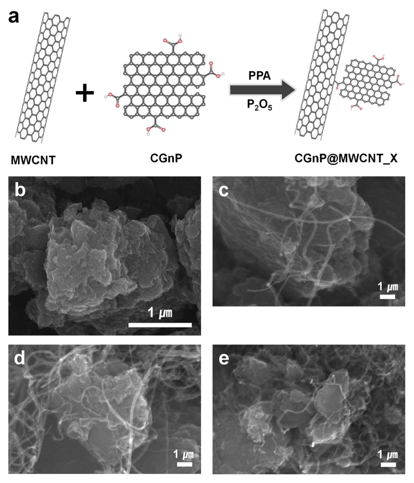
The CGnP@MWCNT hybrid nanomaterials were covalently bonded via an optimized ŌĆ£directŌĆØ electrophilic substitution reaction in a mildly acidic PPA/ P2O5 medium at 130┬░C (Fig. 1(a)) [27,33]. The SEM images describe the surface morphologies of all the materials. CGnP exhibited very small particle sizes (< 1 ╬╝m) and smooth edges (Fig. 1(b)) because the active carbon species (e.g., ions and radicals), created from the carbon bonds, collapsed due to the kinetic energy of the stainless-steel balls and reacted with CO2 to form CGnP. The CGnP was found to be aggregated owing to the strong ŽĆŌĆōŽĆ and van der Waals interactions between the graphene layers, forming large pores. However, the CGnP@MWCNT_X nanocomposites had larger pores and appeared to be less aggregated, indicating the incorporation of carboxylic groups at the edges, which repelled each other to open up the edges of graphene, as shown in Fig. 1(cŌĆōe).
As shown in Fig. 2(aŌĆōb), the HR-TEM images of CGnP@MWCNT_1:1 show a few layers of graphitic sheet and a highly ordered layer structure, indicating that although carboxylic acid groups were introduced through a mechanochemical reaction that uses very high kinetic energy, the CGnP successfully preserved the well-ordered graphitic basal plane. The outermost layers of CGnP and MWCNT were distorted, indicating that CGnP and MWCNT were covalently bonded in the PPA/P2O5 medium (Fig. 2(b), red box). The XRD patterns of CGnP show a sharp peak at 26.4┬░, which corresponds to an interlayer d-spacing of 0.34 nm associated with hexagonal graphite, and a very broad peak at 15ŌĆō30┬░, indicating a high degree of edge expansion [31]. Additionally, the main peaks of CGnP@MWCNT were shifted to the left compared to those of CGnP because of the much higher crystallinity of MWCNT compared with CGnP.
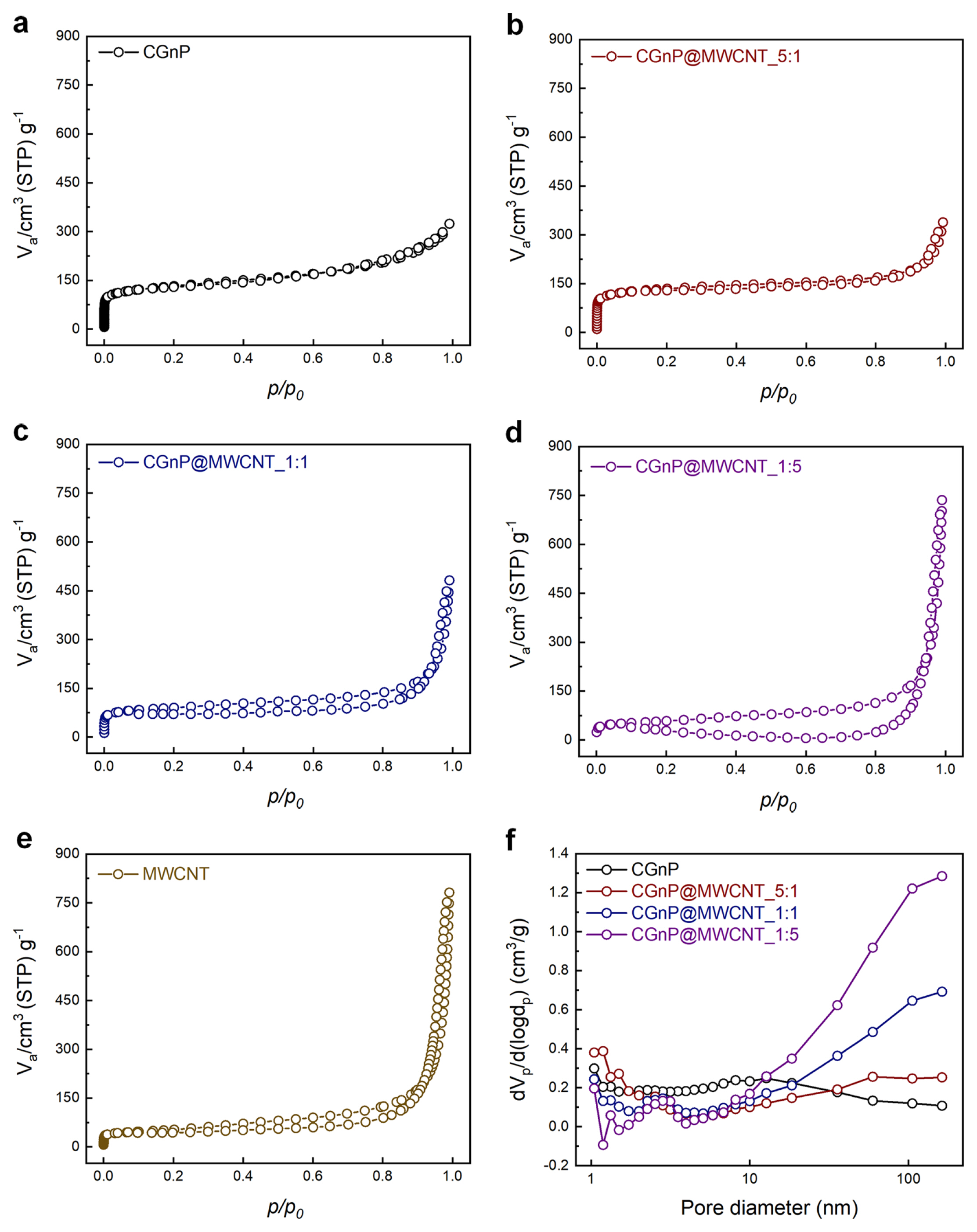
The SSAs were calculated using N2 adsorptionŌĆōdesorption isotherms with the BET method (Table 1). Generally, as the MWCNT content increased, the BET surface area of CGnP@MWCNT decreased because the MWCNT content was much lower than that of CGnP. However, CGnP@MWCNT_5:1 exhibited higher SSAs than CGnP, signifying more delamination into the graphitic sheets through the wedge effect of MWCNT at the edges of CGnP. The pore size distribution was calculated by applying the BarrettŌĆōJoynerŌĆōHalenda method to the adsorptionŌĆōdesorption isotherm. CGnP@MWCNT_1:1 and CGnP@MWCNT_1:5 have the average pore sizes of 20.8 and 24.3 nm, respectively, and formed mesopores (2ŌĆō50 nm), which correspond to the hysteresis loop of 0.2ŌĆō0.9 relative pressure (Fig. 3(aŌĆōe)). The development of mesopores can increase ion diffusion in capacitors and decrease their resistance. Although some mesopores were formed in CGnP@MWCNT_1:5, significantly more macropores (Ōēź 50 nm) were formed because of the excess addition of MWCNT (Fig. 3(f)), and a larger pore diameter could decrease the efficiency of ion diffusion. Therefore, an electrode material with an appropriate pore size is important for improving the performance of the capacitor.
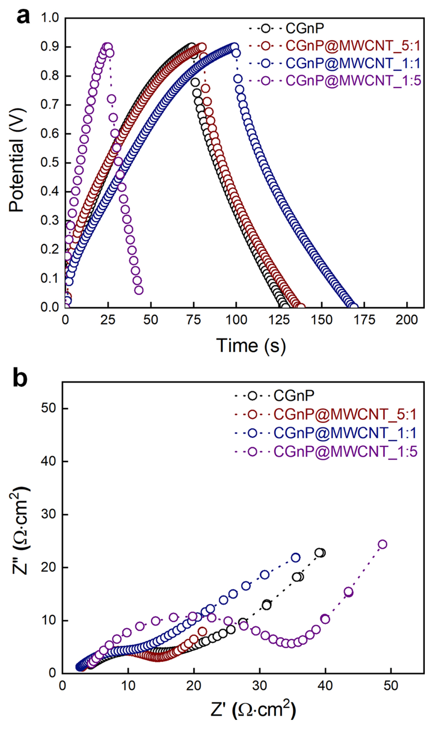
Capacitive performance of the CGnP@MWCNT_X electrodes was evaluated by GCD at constant current density within the potential range of 0 to 0.9 V (Fig. 4(a)). The specific capacitances of the CGnP, CGnP@MWCNT_5:1, CGnP@MWCNT_1:1, and CGnP@MWCNT_1:5 electrodes were 122, 128, 157, and 47 F/g, respectively. The performance of the composite electrode can be induced by mesopore development because the combination with MWCNT contributes to the ionic diffusion of the active surface of the electrode during the charging/discharging process of the capacitor, which decreases the resistance. However, the capacitance of CGNP@MWCNT_1:5, with an excess amount of MWCNT, decreased rapidly because of the development of macropores. Fig. 4(b) shows an EIS curve that was obtained to investigate the ionic and electronic transfer of the CGnP@MWCNT_X electrodes in the same frequency range with an amplitude of 10 mV. EIS is composed of a semicircle and linear Warburg. In the semicircle, the internal resistance (RS) is the sum of the ionic resistance of the electrolyte, whereas the interfacial charge-transfer resistance (RCT) corresponds to the reaction of the active surface of the electrode. The CGnP@MWCNT_1:1 electrode, with a high specific capacitance, exhibited a semicircle at a low frequency. In addition, the calculated RCT values for CGnP, CGnP@MWCNT_5:1, CGnP@MWCNT_1:1, and CGnP@MWCNT_1:5 were 4.28, 2.99, 2.68, and 4.41 ╬®, respectively. Among them, CGnP@MWCNT_1:1 had the lowest RCT and RS values and exhibited an ideal Warburg behavior, which corresponds to excellent ion diffusion.
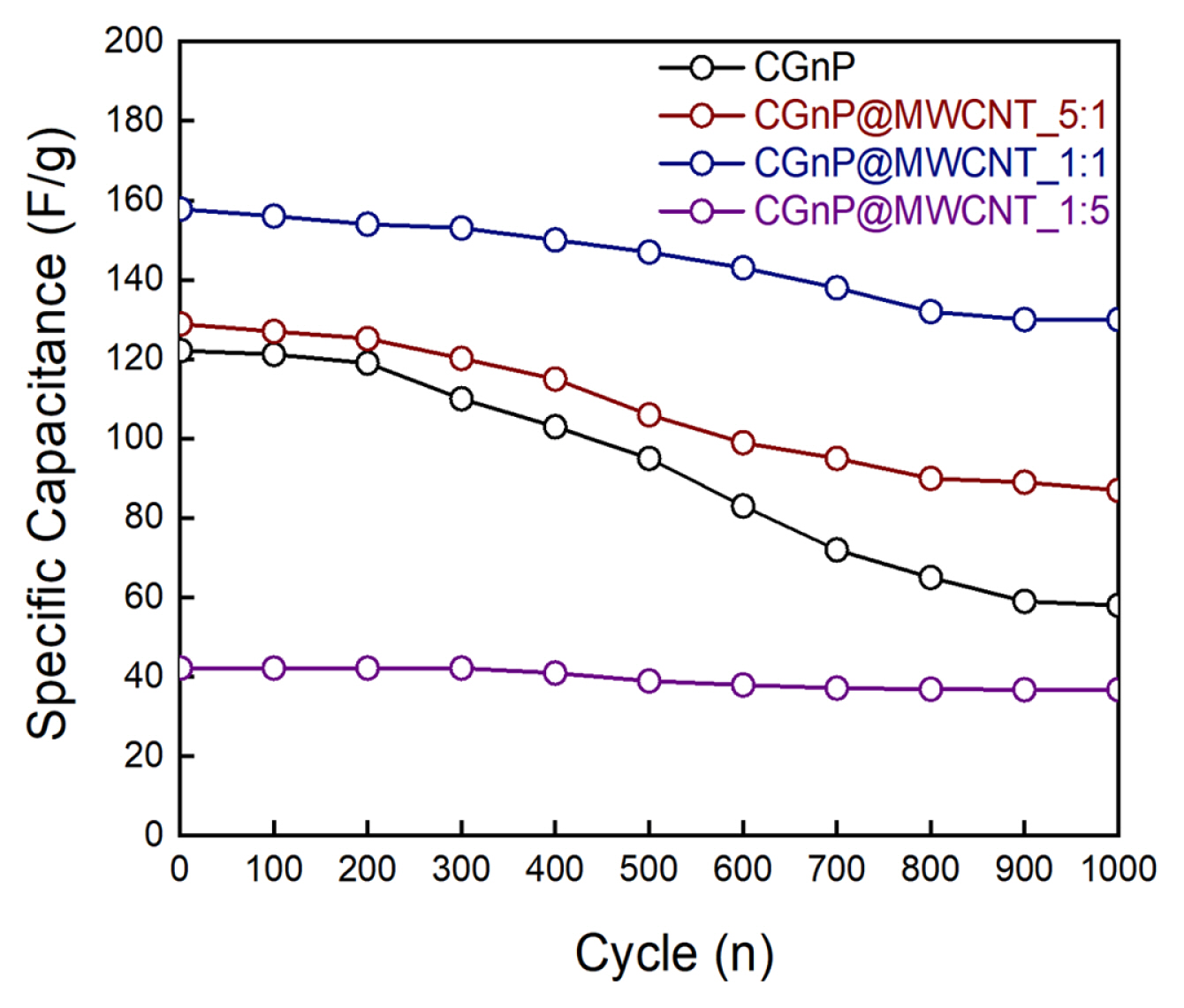
The cyclic stability of the capacitor was investigated by continuously operating the GCD process at a voltage range of 0 to 0.9 V and a current density of 1 mA/cm2. Fig. 5 shows the long-term cycling stability of the prepared electrode material after 1000 cycling operations. Through repeated reactions, the specific capacitance of the single-electrode CGnP was significantly decreased compared to the prepared composite electrode. The composite electrode-based capacitors, except for CGnP@MWCNT_1:5, exhibited excellent power output and improved cycle stability compared to single electrodes such as CGnP or MWCNT. An excess amount of MWCNT can induce an increase in macropore development, which is consistent with the BET results, and a decrease in ion diffusion or the active surface of the electrode. CGnP@MWCNT_1:5 was considered unsuitable to be used as an electrode material for capacitors. Therefore, the CGnP@MWCNT_1:1 composite electrode-based SC has an optimized electrochemical performance with improved stability and excellent capacitance due to the combination of CGnP and MWCNT.
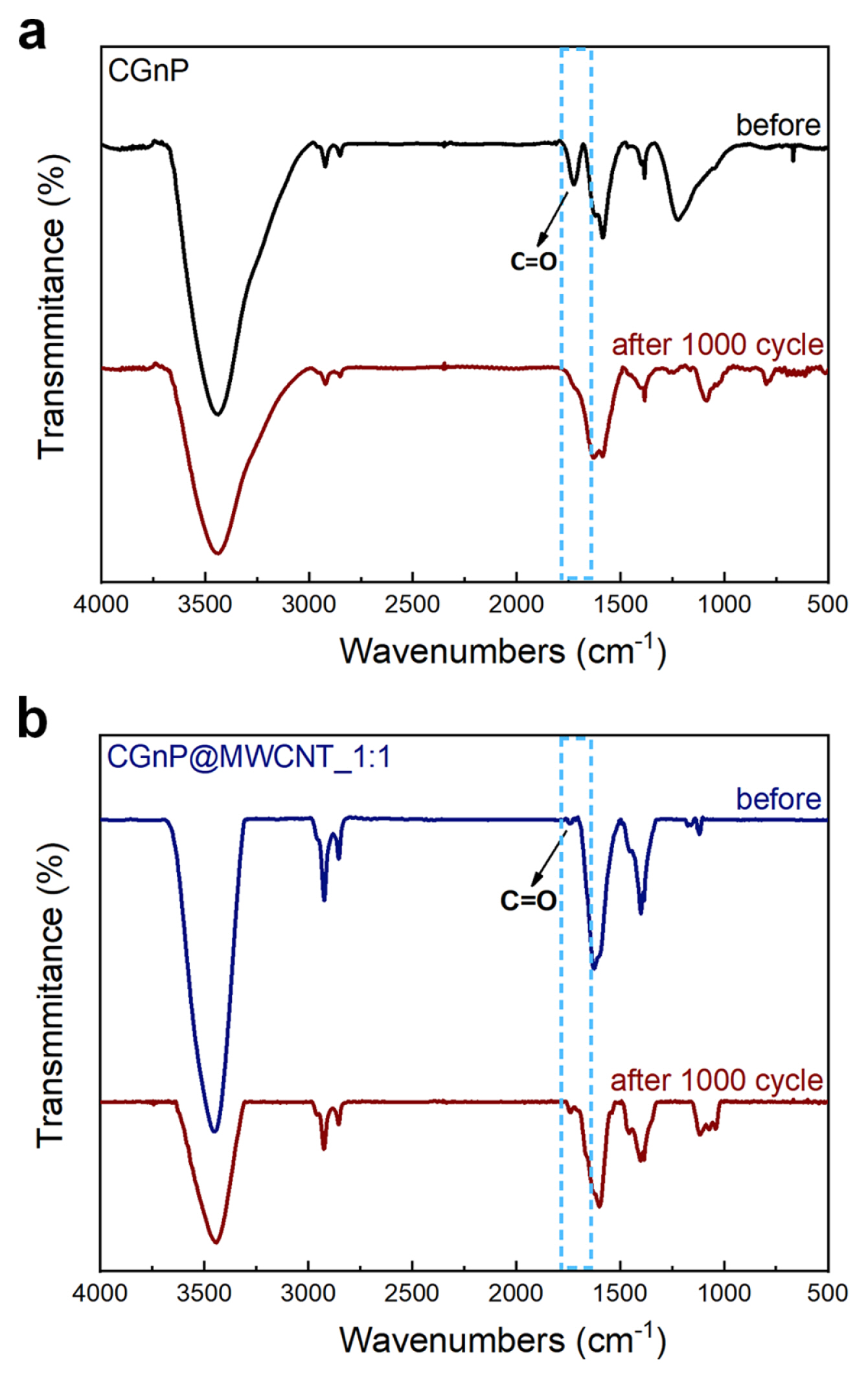
FT-IR measurements (Fig. 6) were performed to gain insights into the chemical changes of the functional groups of the electrode materials caused by electrochemical measurements in an alkali solution. The absorption peaks at approximately 1700 cmŌłÆ1 in all the material spectra correspond to the C=O stretching, which might be attributed to the characteristic carboxylic acid groups of CGnP. To explain the significant decrease in the performance of the CGnP, FT-IR analysis was conducted after 1000 cycles (Fig. 6(a)). The absence of the C=O absorption peaks was due to the decomposition of the carboxylic acid group of CGnP, owing to the repeated chargeŌĆōdischarge process in the alkali solution. In contrast, the carboxylic acid group of CGNP@MWCNT_1:1 did not decompose after 1000 cycles, and a C=O absorption peak was observed in the FT-IR spectrum (Fig. 6(b)). Therefore, the lower C=O absorption peak can be attributed to the covalent bond between the MWCNT and CGnP with carboxylic acid groups at their edges.
4. Conclusions
In this study, graphene-based MWCNT hybrid electrode materials were prepared via an edge-chemistry reaction between MWCNT and CGnP, in which the ratio of CGnP:MWCNT affected the pore size distribution. An increase in the MWCNT content led to the formation of mesopores in the hybrid electrode material. The development of mesopores with appropriate sizes can improve ion diffusion and capacitance. However, an excessively high ratio of MWCNT to CGnP resulted in the development of macropores and decreased the capacitance, as shown in the results. The capacitance of CGnP@MWCNT_1:5, which formed many macropores, showed significantly lower performance compared with CGnP@MWCNT_1:1, which exhibited the highest capacitance of 158 F/g and the lowest resistance value among the hybrid electrode materials. In addition, CGnP@MWCNT_1:1 exhibited excellent stability of 83% over 1000 cycles. Therefore, owing to the development of appropriate size mesopores and a large SSA, CGnP@MWCNT_1:1 proved to be an optimal graphene-based hybrid electrode material to produce electrodes with improved capacitive performance.