1. Introduction
Electrocatalytic evolution of oxygen is an economical, eco-friendly and most demanding technique for both present as well as our future generations and also lessens the pressure on conventional fossil fuels to some extent. In the present study, efforts have been made to prepare and characterize Ni-substituted spinel ferrites to check their performance towards oxygen evolution reaction. The nickel ferrites are inverse type spinel with magnetic properties and they are used in several applications such as in the area of the magnetic field, information storage devices, as electrode material in the production of O2, Cl2, chlorates, H2 evolution, O2 reduction, etc. [1], metal substituted ferrites are used as a catalyst in many reactions such as in the synthesis of NH3 by Haber process [2], decomposition of H2O2 [3]. Metal substituted ferrite nano-particles are used in the detection of dopamine drugs and catalytic organic synthesis [4–7] and they also have been employed in magnetic storage devices, electrochemical energy devices (capacitors, batteries), electrocatalysis and biosensors [8–12], gas sensor [13], multilayer-chip inductor [14], etc. Vast applications of ferrites materials have drawn the attention of scientific communities to prepare these oxide catalysts by several chemical methods such as co-precipitations [15], sonochemical reaction [16], hydrothermal [17], sol-gel [18], citrate precursor technique [19], microemulsion precursors [20], microwave-assisted [21] and egg white combustion method [22]. Among these methods synthesis of nickel ferrites by egg white combustion method is very simple, economical and eco-friendly.
Egg white proteins (globulin, ovomucin, and ovalbumin) have excellent gelling and foaming properties with high nutrient value [23] and are soluble in water and easily form an amalgam with metals. The foaming capacity of egg white proteins is helpful in the synthesis of ferrites nano-crystal. Herein, we have prepared nickel substituted ferrites by the egg white auto combustion method for their electrochemical performance of oxygen evolution in an alkaline medium.
2. Experimental
Nano-sized nickel ferrites, NixFe3-xO4 (x = 0.25, 0.5, 0.75 and 1.0) were prepared by auto-combustion route using egg white as precursor [24]. The stoichiometric ratios of pure nickel nitrate (Merk, 99.9%) and iron sulphate (AR, Merk, 99.9%) were dissolved in 20 mL of double-distilled water. The egg white solution (30 mL of egg white) was stirred at room temperature until the solution was milky white and then metal salts solution was added dropwise into the egg white solution under vigorous stirring. The resultant gel precursors were digested and evaporated at 100°C to form the fluffy solid powder. The fluffy powder was converted into desired oxide nanoparticles by thermal decomposition in an electrical muffle furnace at 550ºC for 5 hours. To check the thermal stability of the fluffy powder precursor and the formation of a stable nickel ferrite phase, the fluffy mass precursor was subjected to the thermogravimetric analysis (model: Mettler Toledo TGA/DSC 3+) recorded in the temperature region of 25 to 600ºC with the constant flow of nitrogen gas. The formation of nickel ferrites was confirmed by FT-IR and XRD techniques. The FT-IR spectrum of oxide was recorded between wavenumbers 400 and 4000 cm−1 in KBr medium using the IR-AFFINITY-1 Shimadzu spectrophotometer and the powder XRD technique (Cu-Kα-radiation, λ 1.54059 Å). The SEM micrographs of oxide powders were taken by using scanning electron microscopy (JEOL/EO, JSM-6490) at different magnifications.
For the electrochemical study, oxide electrodes were prepared by coating the oxide ink onto the previously polished and cleaned glassy carbon electrodes. The oxide ink was prepared by dispersing the 1 mg oxide powder into the solution of 20 μL of nafion (5%) and 40 μL of ethyl alcohol and ultra-sonicate for half an hour [21]. All the electrochemical experiments are performed in a three-electrode single compartment pyrex glass cell consisting of GC/oxide as a working electrode, a Pt foil (Aldrich, 99.9% pure) as a counter electrode and Hg/HgO/1 M KOH as a reference electrode. The reference electrode was connected to the electrolyte through Luggin capillary salt bridge which consists of the agar-agar and salt (KCl). All the potentials quoted in this paper are with respect to the Hg/HgO/1 M KOH (98 mV vs NHE) reference electrode only. The electrochemical performance of oxides electrodes for OER in 1 M KOH was investigated on CHI-608 (CH instrument, USA) by using the same method as given in the literature [21,25,26].
3. Results and Discussion
3.1 Thermogravimetric analysis (TGA)
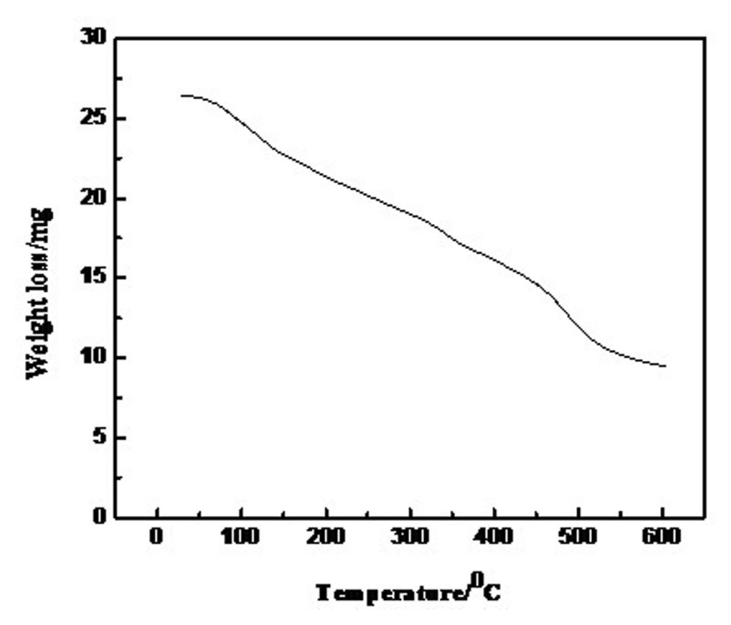
To confirm the formation of a stable oxide phase, thermogravimetric analysis (TGA) of fluffy power precursor of 0.75 mol Ni-substituted oxide was recorded in the temperature range of 25 to 600ºC with a constant flow of nitrogen gas and the thermogram shown in Fig. 1. This indicated the gradual decrease of weight of the sample with the rise in temperature due to decomposition of organic moieties, iron sulphate and desorption of water from fluffy mass and also showed the formation of a stable oxide phase after 500ºC [27].
3.2 FT-IR
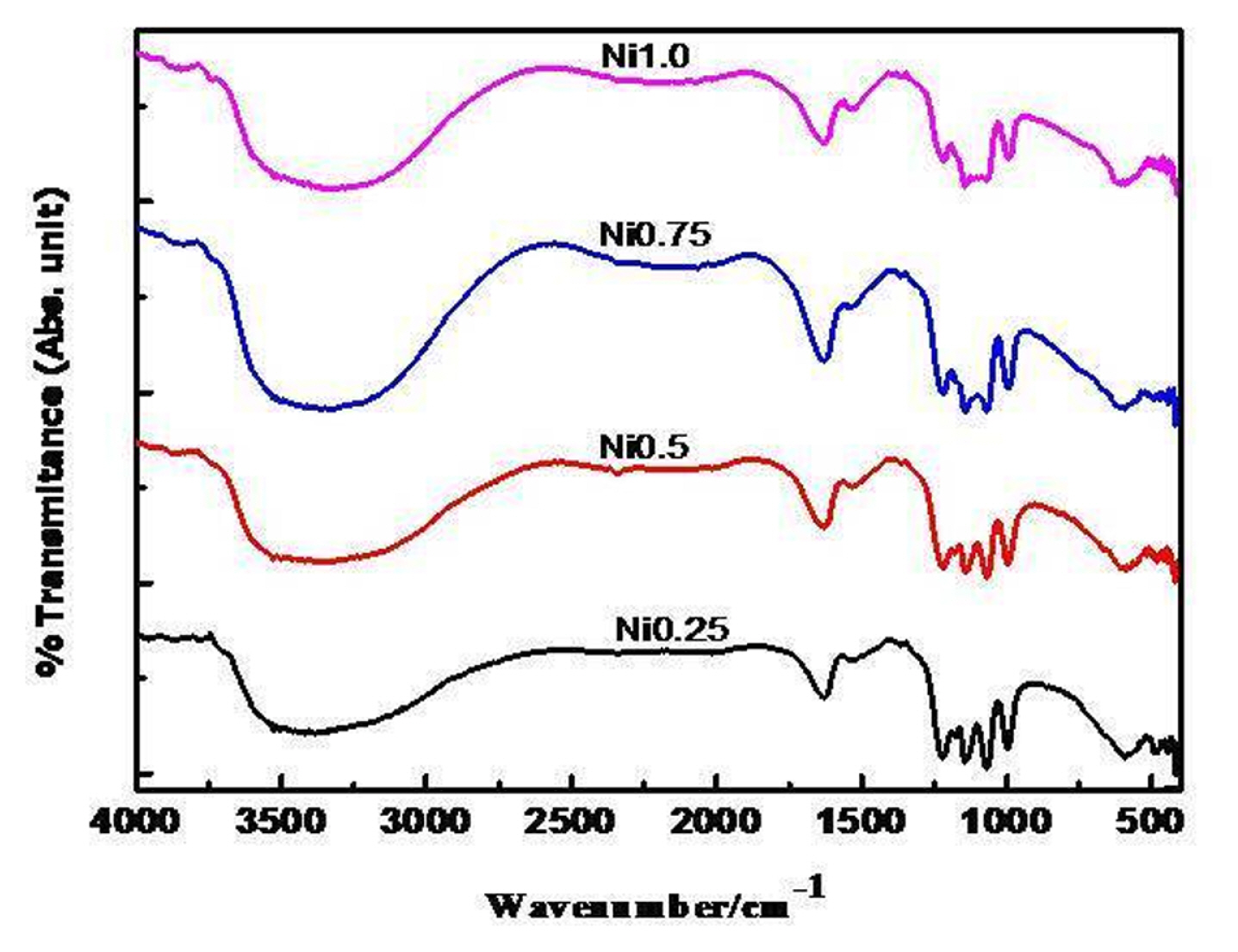
Ni-substituted ferrites prepared at 550ºC for 5 h are analyzed by FT-infrared technique in the wavenumber region from 400 to 4000 cm−1 and the recorded FT-IR spectra are given in Fig. 2 and exhibited the characteristic absorption peaks at ~422 ± 2 and ~592 ± 2 cm−1 are ascribed as M-O stretching vibration in octahedral and tetrahedral voids and another absorption band at ~1120 ± 4 cm−1 ascribed as a tetrahedral Fe3+-O2− stretching vibration. IR spectra also exhibited vibration bands at ~1385, ~1630, and 2335 cm−1 indicating the presence of carboxylate ion, water and adsorbed CO2 [22].
3.3 XRD
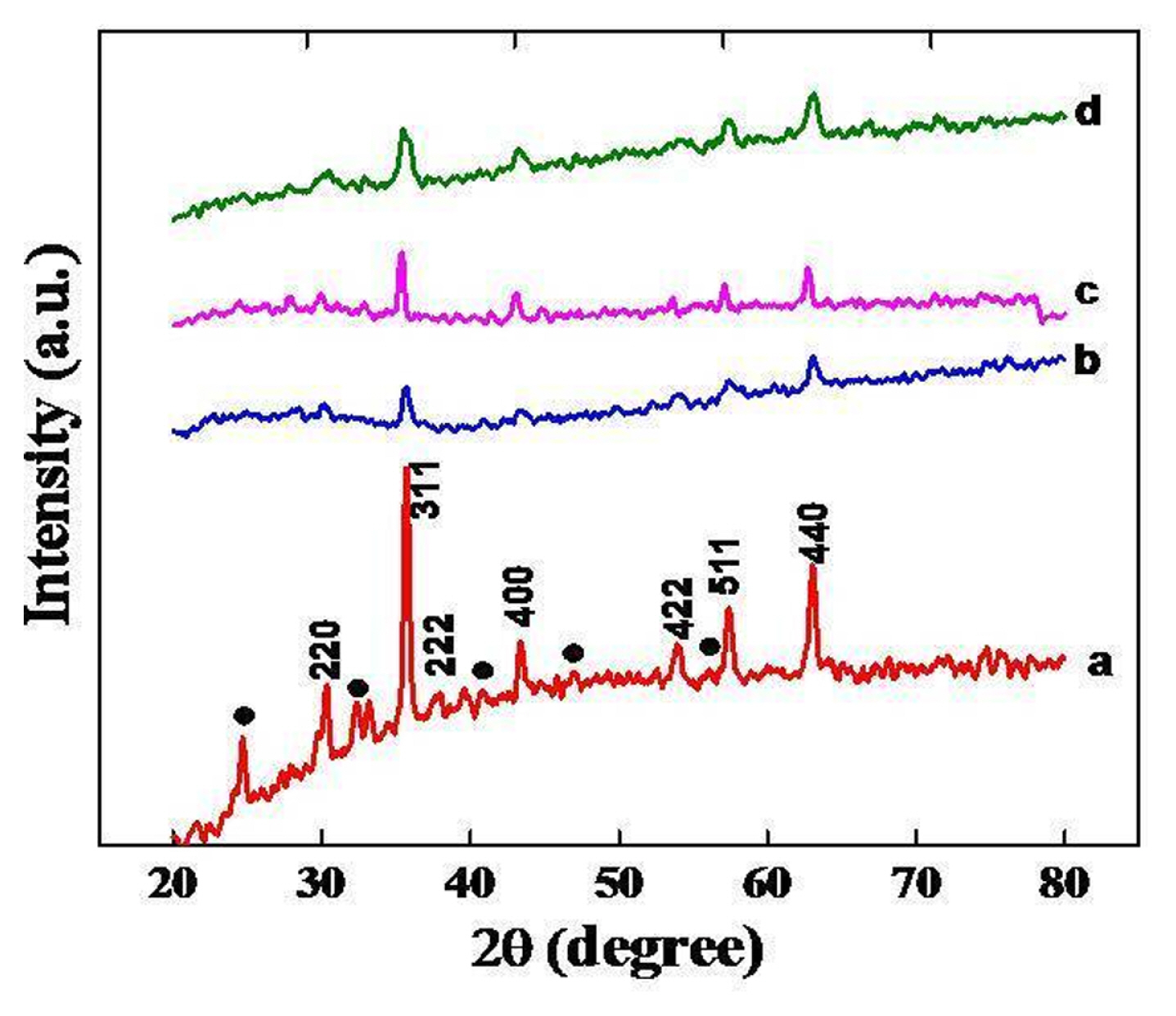
The formation of the spinel phase was established by X-ray powder patterns of oxides prepared at 550ºC for 5 hrs. XRD powder patterns of nickel substituted oxides are shown in Fig. 3, which suggest the formation of crystalline spinel phase with peaks corresponding to (220), (311), (222), (400), (422), (511) and (440) planes in agreement with JCPDS file No. 74-2081 of NiFe2O4 [28]. Fig. 3, also showed the presence of some additional low intense peaks corresponding to the formation of α-Fe2O3 along with the spinel phase as a trace of impurity. The crystalline size of nickel substituted oxides is calculated from observed values of FWHM of the most intense peak of the crystal plane using the Debye Scherrer formula (
S = 0.9 × λ β cos θ
3.4 Scanning electron microscopy (SEM)
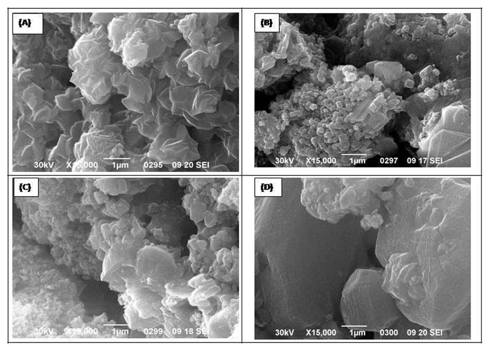
SEM micrographs of 0.25, 0.5, 0.75 and 1.0 mol nickel substituted ferrites prepared at 550ºC for 5 h were shown in Fig. 4. Micrographs indicate the irregular agglomeration of oxide nanoparticles and Ni0.25Fe2.75O4 shows a comparatively higher degree of agglomeration with a rosy appearance. Substitution of nickel in the Fe3O4 matrix improved the crystallinity and appeared as granular nanoparticles. A comparatively larger reduction in crystallite size was observed in 0.5 and 0.75 mol Ni-substituted ferrites. While ferrite with 1.0 mol Ni has more compact granules.
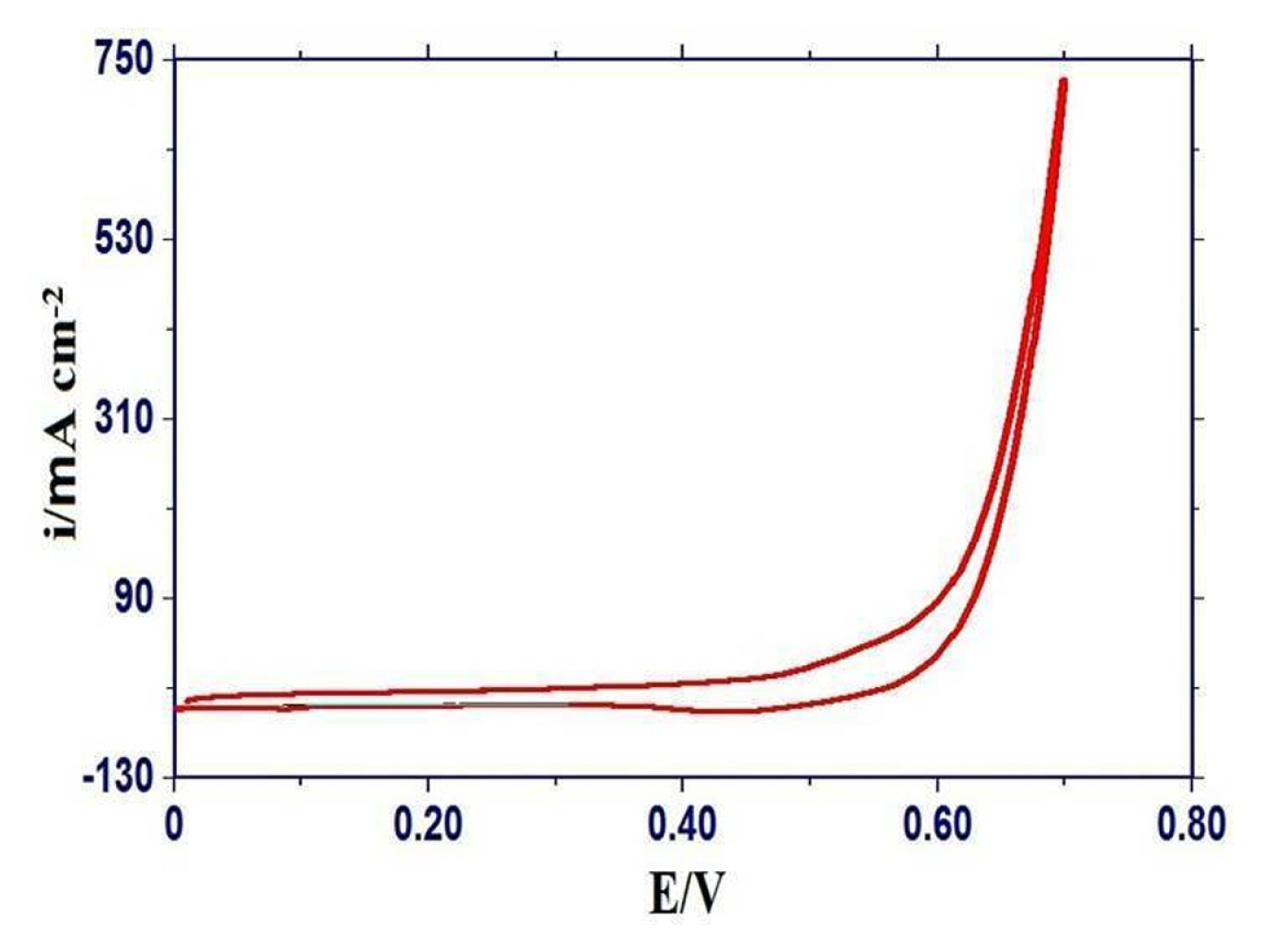
3.5 Cyclic voltammetry (CV)
The cyclic voltammograms of each oxide on a glassy carbon electrode were recorded in the potential range of 0 to 0.7 V at 20 mV s−1 in 1M KOH to observe the occurrence of redox reaction on the oxide/electrolyte interface. A representative cyclic voltammogram of the GC/Ni0.75Fe2.25O4 electrode was given in Fig. 5 and exhibited the absence of redox peaks in the selected potential region. Similar nature of cyclic voltammogram of Fe3O4 was also observed on Ti support [30]. Cyclic voltammograms of Ni-substituted oxide electrodes showed a comparatively higher value of current density (ia) for the bare GC as well as non-substituted ferrite electrodes.
3.6 Oxide Roughness Factor (RF)
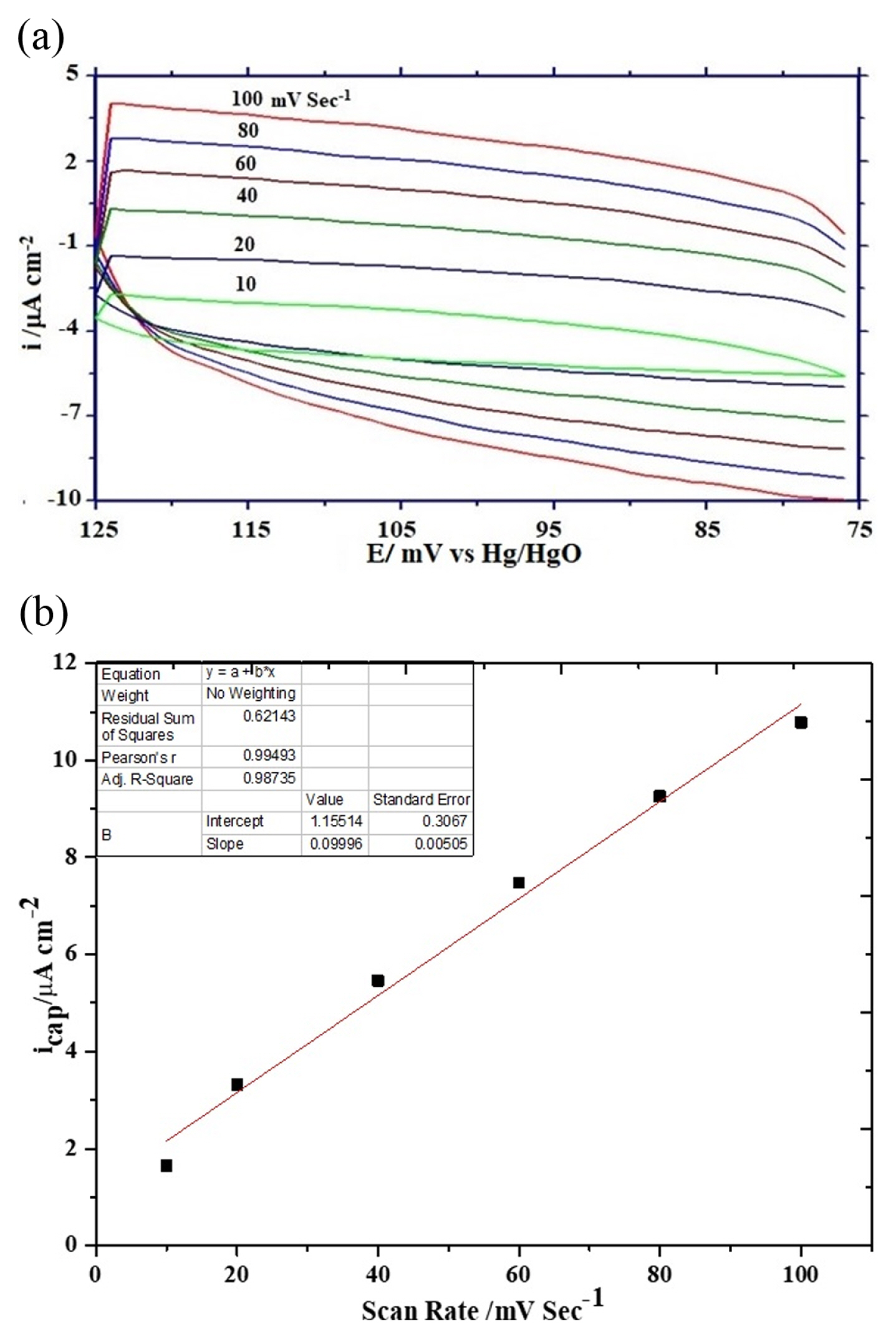
The rate of electrochemical oxygen evolution is expressed either in terms of apparent current density (ia) normalized by the geometrical surface area of the electrode or true current density (it) normalized by the oxide roughness factor. The oxide roughness factor of each oxide electrode was determined by performing a cyclic voltametric experiment in 1 M KOH at varying scan rates between potential regions of 0.075 to 0.125 V at 25ºC. The RF value of oxide electrodes was calculated from the double-layer capacitance (Cdl) value obtained from the slope of current density vs scan rate plot. Representative cyclic voltammograms at varying scan rates and a plot of current density vs scan rate are given in Figs. 6(a) and 6(b) respectively. The oxide roughness factor was estimated by assuming the double layer capacitance value of a smooth oxide surface is equal to 60 μF [31]. The observed values of oxide roughness factor are considerably lower than those reported in the literature [32] and also show the nickel doping in ferrite matrix not significantly influenced oxide roughness but very marginally reduced and hence increased the electrocatalytic activities towards OER.
3.7 Electrocatalytic activities
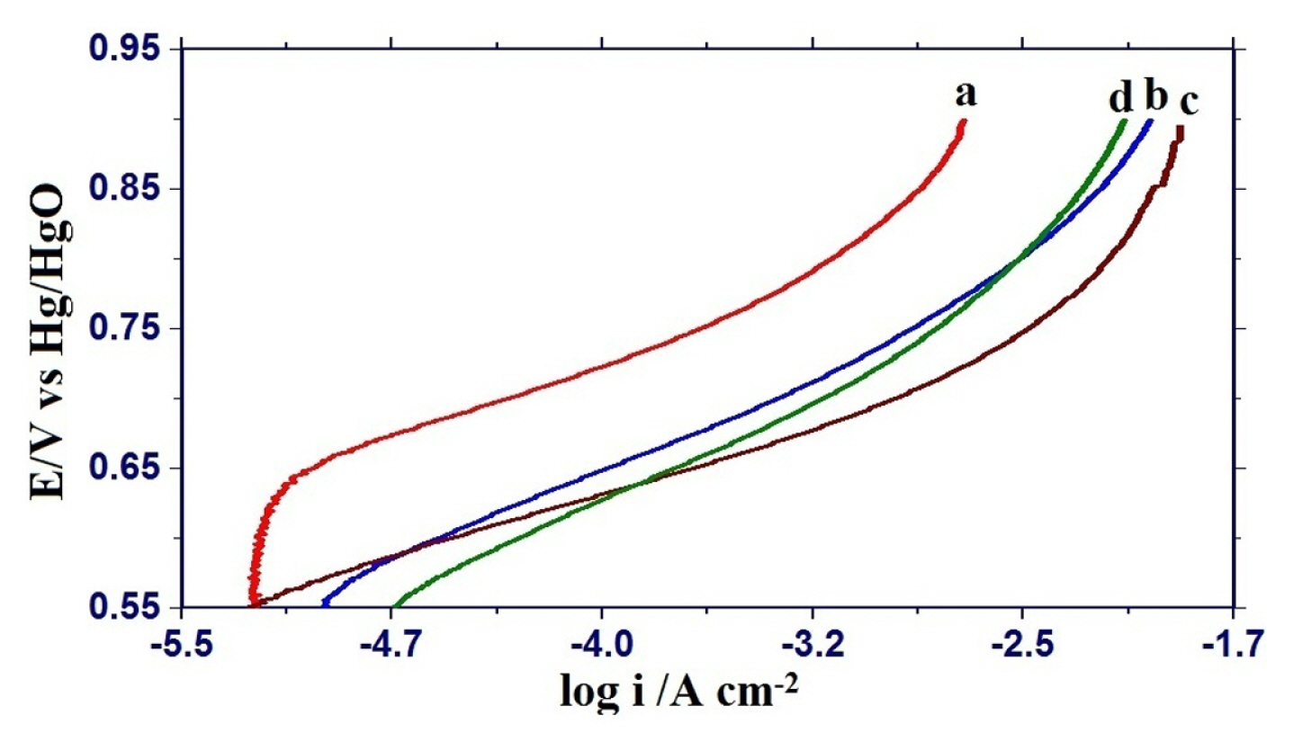
Electrocatalytic activities for oxygen evolution reaction on nickel substituted oxide electrodes were monitored by recording the iR-corrected Tafel polarization curves in 1 M KOH solution at 25ºC (Fig. 7) and the observed results are given in Table 1. Tafel polarization curves of each oxide electrode are almost similar and showed the two distinguishable Tafel regions at lower and higher overpotentials. The values of Tafel slopes were found to be 74 ± 15 and 107 ± 16 mV decade−1 at lower and higher overpotential regions, respectively. The introduction of nickel in the iron ferrite matrix reduced the Tafel slope and maximum reduction was observed in the case of 0.75 mol nickel substituted ferrite. Electrocatalytic activity based on current density (I) at E = 850 mV, both apparent current density (ia) as well as true current density (it) are considerably increased by nickel substitution in the Fe3O4 matrix. Maximum enhancement in electrocatalytic activity was observed in the case of 0.75 mol nickel substituted iron ferrite.
An increase in electrocatalytic activity with metal ion substitution in Fe3O4 lattice is due to a change in the electronic and magnetic properties of oxide catalyst [33]. Orehotsky et al. [34] observed an increase in room temperature saturation magnetization with nickel substitution in iron ferrite. Iwakura et al. [35,36] also found an increase in saturation magnetization with metal substitution in the Fe3O4 lattice. They also observed that electrocatalytic activity for oxygen evolution reaction increased with the increase in Bohr magneton.
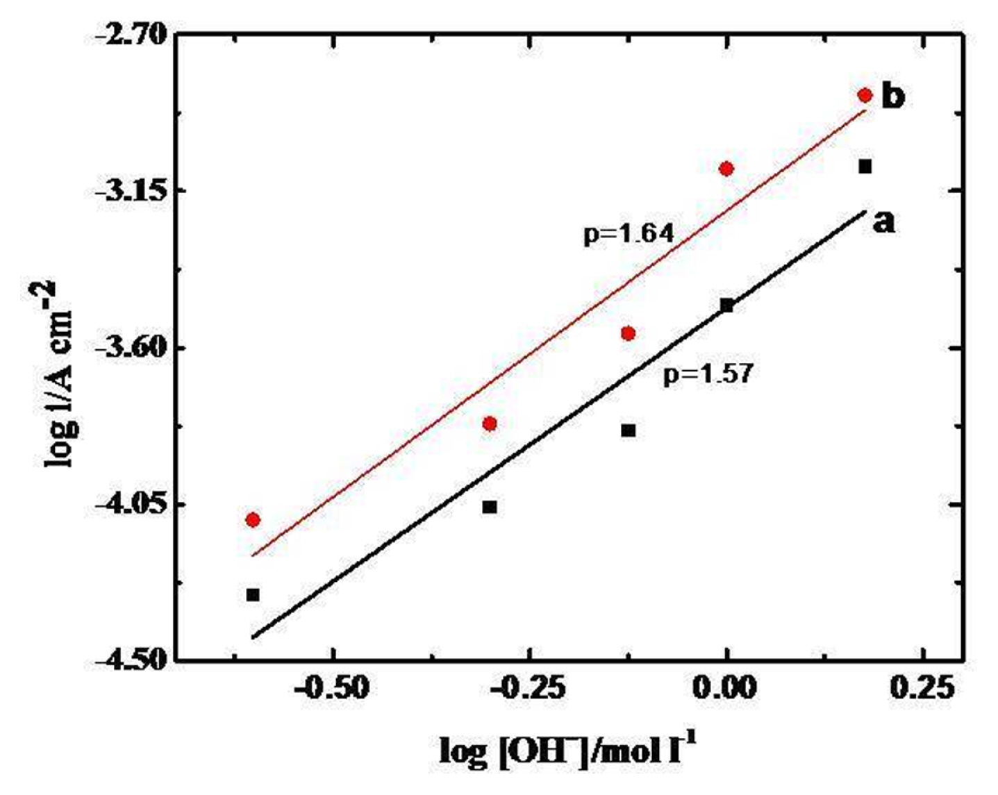
To find out the order of reaction (p) with respect to [OH−] the anodic Tafel polarization curves of GC/Oxide electrodes were recorded at different KOH concentrations (0.0–1.5 M) keeping the ionic strength of medium constant (μ = 1.5). The value of p was calculated from the slope of log i vs log [OH−] plot (Fig. 8), at a constant potential (E = 0.7 V) across the oxide film/KOH interface in the lower overpotential region. The estimated value of the order of OER is approximately 2. A similar order for OER was also reported in the literature, Iwakura et al. [36] found second order with a higher value of the Tafel slope (110–115 mV decade−1) for NiFe2O4 on Pt-substrate. However, Singh et al. [32] found second order with a lower Tafel slope 45 mV d−1 on NiFe2O4 on Ni support obtained by the thermal decomposition method, Orehotskey et al. [36] also found the lower value of Tafel slope (37–47 mV decade−1) on nickel ferrites prepared by freeze-drying technique.
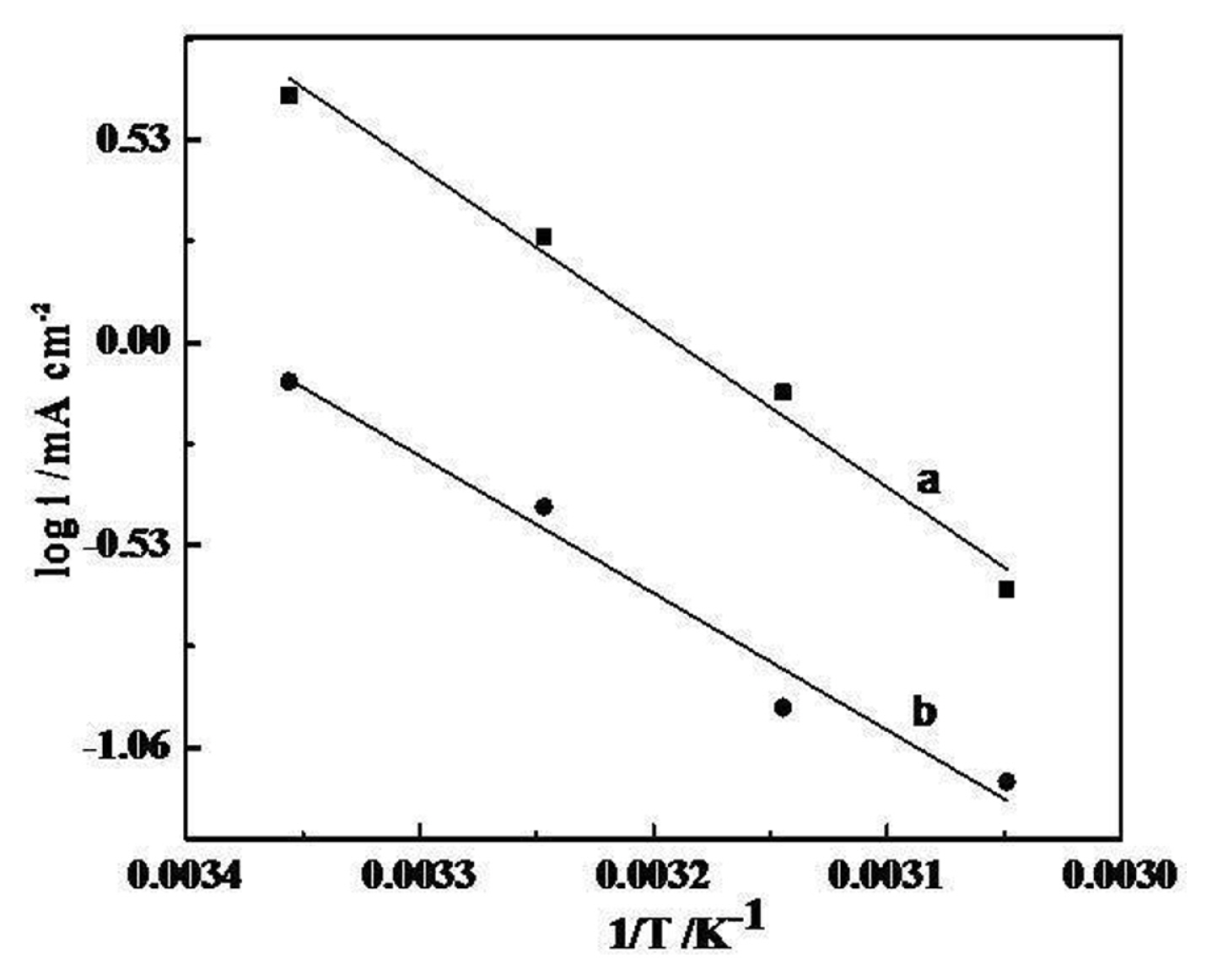
The thermal response of fabricated electrodes for OER has also been studied in terms of apparent electrochemical activation energy (
Δ H c 0 ≠ Δ H e l 0 ≠ Δ S e l 0 ≠ Δ H e l 0 ≠ 1 T
4. Conclusions
The present investigation has shown that the preparation of nickel ferrites by auto combustion method using egg ovalbumin is simple, economical and produces nano-sized oxides with more crystallinity in the spinel phase. The substitution of Fe by Ni in Fe3O4 lattice significantly reduces the Tafel slope and enhances the electrocatalytic activity towards OER in an alkaline medium and they can be used as electrode materials for energy storage devices and other applications.