1. Introduction
Hot electron electrochemistry, which provides tools to work beyond the electrochemical window of water restricting the traditional electrochemistry aqueous solutions, has been explored already for quite a long time. The principles of utilizing hot and hydrated electrons in analytical applications have been earlier studied by using thin insulating filmcoated electrodes [1–5]. Semiconductor electrodes and thin-insulating oxide-coated electrodes are particularly attractive in this field because the electrons and holes can remain separated in energy in the conduction and valence band, respectively. The unusual ability to directly inject/emit electrons into solutions forming solvated electrons is the key point in the properties of these relatively new electrode materials. Solvated electrons, and hydrated electrons in water, are the chemist’s perfect reducing agent in many ways. Recently, we made efforts to develop low-cost replacements [6,7] for chemically quite non-resistant oxide-coated aluminium electrodes [8–10] and typically a bit too expensive oxide-coated silicon electrodes [7,8] for hot electron injection into fully aqueous electrolyte solutions [1–5].
We have earlier shown that by using thin-film manufacturing technologies quite sophisticated electrode chips can be made on glass chips e.g. by utilizing aluminium sputtering and atomic layer deposition of alumina or from silicon chips [11,13,14]. Such electrodes can be used in disposable manner for e.g. bioaffinity assays that are important in real-world point of care testing [12,15,16]. In these assays, the lowest determination limits are typically obtained by using aromatic Tb (III) chelates as labels, however many organic luminophores [5,17–19] or Tris(bipyridine) ruthenium(II) [Ru(bpy)32+]-type labels [20,21] can also be used when lower assay sensitivity is sufficient. These labels are typically excited with sequential one-electron reduction and oxidation steps either by red-ox, or ox-red routes depending on the (1) redox properties of the luminophores or ligands of the complexes, and (2) the stability of luminophore or ligand radicals in the aqueous solution [4,18,19,22,23].
We have previously shown that hydrated electrons can be obtained by hot electron injection into aqueous solutions. These conclusions were based on the measurements using various hydrated electron scavengers with the known reaction rate constants obtained from pulse radiolysis studies. The hot- and hydrated electrons allow to carry out difficult one-electron reduction reactions in aqueous solutions that are usually not obtainable using traditional electrochemistry and active electrodes. These highly reducing intermediates also enable efficient production of strongly oxidizing radicals by one-electron reduction from precursors such as hydrogen peroxide (hydroxyl radical), peroxydisphosphate (phosphate radicals) and peroxydisulfate (sulfate radicals) [1,17,23]. Thus, strongly reducing, but also simultaneously strong oxidizing conditions can be created by the hot- and hydrated electrons.
Our group has utilized hot electron injection into aqueous solution only in generating hot electron-induced electrochemiluminescence (HECL) of our labels for bioaffinity assays, but there are many other application areas for hot electron electrochemistry. Solvated electrons can be utilized in organic chemistry [24] and in inorganic chemistry [25,26] and e.g. in disinfection of potable water and treatment of waste waters [27–29]. Most common methods for generation of hydrated electrons have so far been (1) high energy irradiation of water (either high energy electrons or photons [25], (2) photoemission of electrons from electrodes [30], (3) photoionization and photodetachment of solutes [31–33], (4) dissolution of wide-band gap inorganic crystals containing trapped electrons [34].
Our recent developments, composite electrodes, have been so far made by using polymer materials, such as polystyrene [6,7] and ethyl cellulose [35] as a matrix that can easily be dissolved into common organic solvents and can then immediately be doped with suitable conducting particles by simply mixing and sonicating with ultrasound. The doped polymer is finally spin-coated upon a conductive substrate such as on a metal or a strongly doped semiconductor disc. Thus, the final structure of C/CPDP (conductor/ conducting particle doped polymer) composite electrode has been created [6,7,35]. In these composite electrodes, the final electron injection to solution is typically occurring through an ultrathin polymer layer naturally formed on top of the conducting particles during manufacture process [7]. However, it is possible that those conducting particles in direct contact with the electrolyte on the surface may in addition inject hot electrons by field emission into electrolyte solution, either as such, or through a hydrogen gas barrier generated by hydrogen evolution [36].
This time we made efforts to manufacture composite electrodes in a very simple way that could produce composite electrodes usable also in many organic solvents, and mixtures of aqueous electrolyte solutions and solvents miscible in water, to inject hot electrons into these solvents or solvent mixture solutions. Nylon 6,6 was chosen as a polymer since it is known to have high mechanical strength, rigidity, good stability under heat and high chemical resistance [37].
Nylon 6,6 is one of the most commonly used polyamides in industries and in 1938, it was first used in toothbrush filaments production [38]. It consists of two monomers, containing hexamethylenediamine and adipic acid. As the melting point is related to the degree of hydrogen bonding between the chains, therefore, nylon 6,6 has a sharp melting point of 264°C due to the density of amide groups leading to hydrogen bond formation. In addition, the symmetrical structure of even-even monomers of nylon 6,6 and its amide groups allow the hydrogen bonds to be formed in any direction that the chains are facing, piling up on top of each other. This phenomenon leads to faster crystallization rate and processing window. Though characteristically, nylon has the ability to absorb significant amount of water in general [37], the higher crystallinity of nylon 6,6 also helps its lower moisture absorption, and thus affects its modulus and tensile strength.
Nylon 6,6 also shows much higher fatigue resistance, advantageous abrasion resistance and coefficient of friction. Usually, the volume resistivities of dry nylon are between 1014–1015 Ω cm. Dry nylon 6,6 has dielectric strength of 24 kV/mm (short time) and 11 kV/mm (step-by-step) [37]. In terms of chemical resistance, nylons have been proven as an excellent material, as polyamides are known to be particularly resistant towards nonpolar materials e.g. hydrocarbons. However, strong acids and phenols can disrupt the hydrogen bonding and even can dissolve nylons and nylon 6,6 can be dissolved e.g. in ethylene glycol above 160°C. Nylon 6,6 is being industrially synthesized, and it is currently an easily obtainable low-cost material for the present applications.
In the present study, nylon 6,6 was first dissolved in hot formic acid and then doped either with graphite particles or carbon black particles. We used two types of graphite particles and two types of carbon black particles and first examined the optimal composition of each of the DP (doped polymer) layers of C/DP electrodes. The DP mixture was then dispensed on a round metal substrate and very simply cured on a hot plate at a suitable temperature.
Finally, we studied the analytical performance of the present composite electrodes for detecting Tb (III) chelate and Ru(bpy)32+ chelate on the basis of their cathodic HECL. Our aromatic Tb (III) chelates cannot be excited on the basis of traditional electrochemistry at active metal electrodes due to the insufficient electrochemical window available because of hydrogen and oxygen evolution reactions, but are showing strong chemiluminescence in the presence of hydrated electrons and highly oxidizing radicals [3,4]. The excitation of Ru(bpy)32+ chelate by hydrated electrons and oxidizing radicals [39] as well as by hot electron injection into aqueous solution has been studied in detail earlier [23].
2. Experimental
2.1 Chemical and reagents
Nylon 6,6 pellets from Sigma-Aldrich was used as a matrix polymer of composite ink layers and four types of individual conducting particles were studied (Table 1).
The solvent for making the composite material i.e. ink was 100 % formic acid (Fisher Scientific). The composite material mixtures were made by using Cole-Parmer ultrasonic homogenizer.
The measurements solutions were made from distilled water and appropriate salts. 0.20 M borate buffer containing 0.100 M of sodium sulfate (Sigma-Aldrich) was made in 0.05 M sodium tetraborate decahydrate solution (Na2B4O7·10 H2O, Merck). The weighed amount of sodium tetraborate was calculated to yield 0.05 M sodium tetraborate solution, since each mole of tetraborate produces two moles of boric acid and two moles of borate ions upon dissolution. The stock solution (0.05 M) of peroxydisulfate was made from the product of Merck. Stock solution of terbium (III) chelate (chelate ligand was terbium (III)-4-(phenylethyl) (1-hydroxybenzene)-2,6diyl) bis-(methylenenitrilo) tetrakis (acetic acid), synthesized in University of Turku) (abbreviated as Tb (III)-L hereafter) was 0.01 M. For pH sensitivity study in section 3.5.2, two additional luminophores: Tris (2,2′-bipyridyl)dichloro-ruthenium (II) hexahydrate) solvated as Ru(bpy)32+ chelate in the solutions, and fluorescein from Sigma-Aldrich were used.
2.2 Fabrication of electrodes
Round brass substrates were made with a diameter of 12 mm from technical brass sheet (soft brass 0.002 thick 44 gauge 12” × 30”) purchased from K&S precision metals. Then masks made of Teflon adhesives (Irpola Oy, Turku) were added on top of the substrates as masks revealing a round area of 0.64 cm2 in the middle of the substrate for dispensing the composite ink. Each of the composite inks were then dispensed in the wells surrounded by teflon and the electrode was dried on a hot plate at a temperature of 90°C for two hours (Fig. 1a). The electrodes were let to cool before use. After the use, these composite inks can be easily washed off or removed using common organic solvent, and then the substrates can be reused for fabricating new composite electrodes. In this study, oxide-covered aluminium discs as electrodes, cut from 99.9% pure aluminium (Merc art. 1057, batch 721 k4164557) were used for comparison with the composite electrodes.
The most significant part of the electrode fabrication process is the preparation of the composite ink. In order to prepare the composite inks, carbon particles and nylon 6,6 were weighed in the vials and kept at 90°C for one week together with concentrated formic acid. Prior to the dispensing each composite ink variant containing different mass ratios of dry matters and solvent were sonicated for 10 minutes (amplitude 40%, 45s on-off-cycle; Cole-Parmer ultrasonic homogenizer). The dry matter consisted of nylon 6,6 and carbon particles where the weight of nylon 6,6 was always 80% of that of total dry matter. Different mass ratio of dry matter (50, 75, 100 and 150 mg/mL of solvent) were tested in order to find the optimum consistency of the ink based on the formulated ink’s viscosity and ability of injection of hot electrons. Finally, the total dry material concentration was selected to be 75 mg/mL in the study experiments. Interestingly, the replacement of carbon particles by ~100nm particle sized silver nano powder (Sigma-Aldrich) produced composite electrodes that could not produce a measurable amount of HECL.
The measuring cell was composed of two parts that could be screwed together. The lower part provided electrical contact to the brass substrate discs and upper part provided teflon vial for dispensing the electrolyte solution onto the working/composite electrode area, and a platinum wire as a counter electrode (Fig. 1b). The electrolyte solution volume in the measurements was always 150 μL.
2.3 Measuring instruments and measurement procedure
The instrument setup consisted of an in-laboratory built coulostatic pulse generator, a photomultiplier tube module (Perkin Elmer MH1993 1364-H-064) for optical detection, a photon counter (Stanford Research Systems SR-400), a preamplifier (Stanford Research Systems SR-445), Nucleus Inc MCS-II multiscaler card and two PC units. For DC excitation a laboratory DC voltage source was used instead of coulostatic pulse generator measurements. The sheet resistivity of different composite electrodes was measured with Jandel RM3000 test unit equipped with a cylindrical four-point probe head to avoid contact resistance.
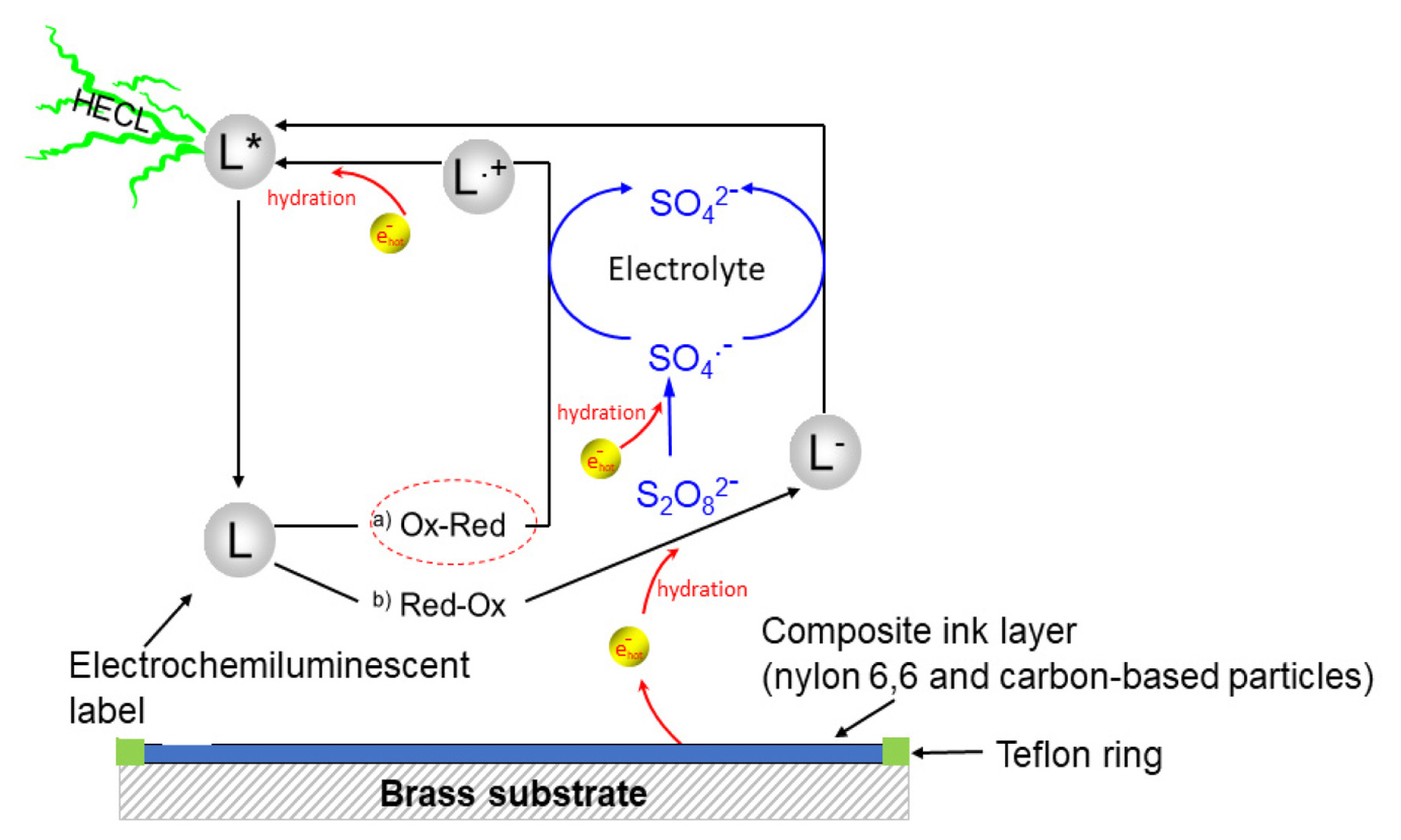
As mentioned in section 2.1, all the measurements were conducted in 0.20 M borate buffer containing 0.10 M of sodium sulfate as supporting electrolyte, using a solution volume of 150 μL. The HECL measurements begun with measuring reference value using 99.9% pure aluminium discs, where the cathodic excitation pulses were generated using the pulse generator when constant charge voltage pulses of −41.8V was delivered with a pulse charge of 31.5 μC and a pulse frequency of 50 Hz. Simultaneously, optical detection was performed using the aforementioned photomultiplier, assisted with the amplifier, through an interference filter (i.e. for the electrochemiluminescent labels Tb (III), fluorescein, and Ru(bpy)32+ - a 545±40 nm, 550±40 nm and 600±40 nm respectively) passing the label specific spectral line. Besides, the amplified photon pulses were also recorded in the multiscaler card. Similarly, following the reference measurement, then all the composite electrodes were individually tested replacing the aluminium, repeating the same measurement procedure. A schematic figure of the overall reaction pathways (a. ox-red pathway, and b. red-ox pathway) in composite electrodes during the HECL measurement is depicted in Fig. 2.
3. Results and Discussion
3.1 The effect of the weight fraction of conducting particles
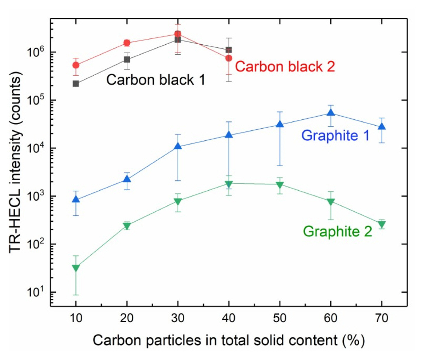
When the weight fraction of conductive particles of the total solids of the composite coatings was studied, it was observed that the coatings with higher weight fraction than 40% became too brittle to be usable in case of carbon black particles, but graphite particles allowed the experiments up to 70% of carbon particles (Fig. 3).
It was observed that, when the starting point was 10% of conductive particles of the total mass of the compositions, all the electrodes were working for the purpose, but about two orders of higher magnitude HECL intensity could be obtained with graphite particles with much higher weight fraction of the conductive particles. In case of graphite 1, the optimum was at about 60% of graphite and with graphite 2 consists of smaller particle size, the optimum weight fraction was already at about 45% of graphite of total solids.
However, with smaller carbon particle sizes a couple of orders of higher magnitude HECL intensity was obtained. Carbon black 2 having the smallest particle size, i.e. 20 nm (Table 1), appeared to be the best conductive particle source for these composite films upon the metal electrodes, as a whole. However, both carbon black 1 and carbon black 2 showed the optimal weight fraction of carbon particles to be at about 30% where they gave the same intensity (photon count) as the best result of all.
3.2 Measurement of sheet resistance in composite films
Sheet resistance measurements of the composite films were carried out using 4-point probe head from the composite films fabricated on top of the non-conductive polyester film. The sheet resistance decreased as a function of increasing weight fraction of carbon as expected. The best performance in electrical conductivity was obtained with compositions having a sheet resistivity of about 100 Ω/□ (Fig. 4). The composites containing more than 50% of carbon black cracked upon drying and could not be used in these measurements.
There are three important areas for current transport in the composite film. First, charge transfer from the metal substrate to the carbon particles at the metal-composite interface. Secondly, electron transport through the composite film via resonance tunneling between the carbon particles in the film, and finally electron transfer or emission into the electrolyte solution at the composite film-electrolyte interface. From Fig. 4, in terms of sheet resistance, the overall performance of carbon black 1 composite film seems to be the best, compared to the other three composite films.
3.3 Characterization of the composite electrodes
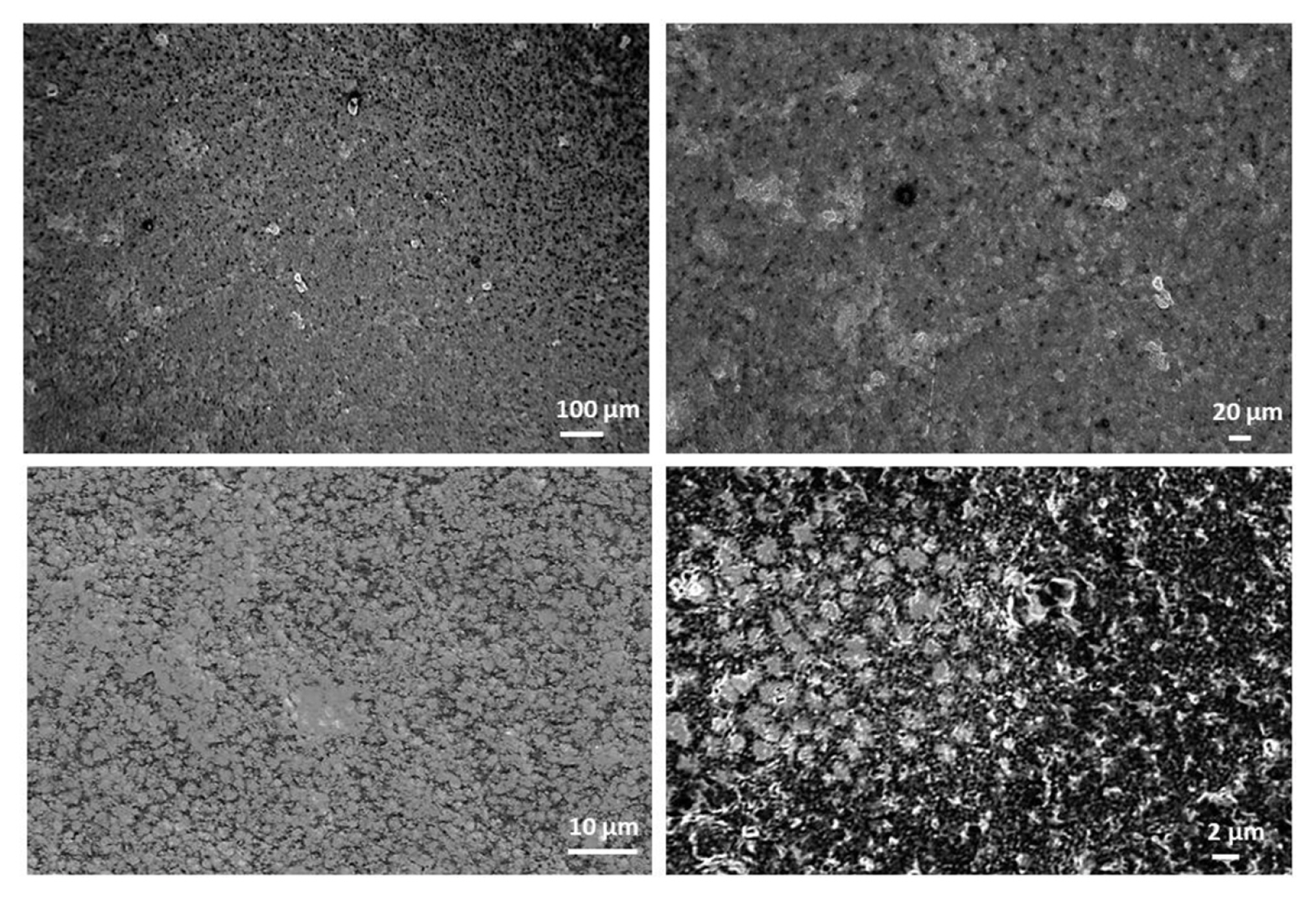
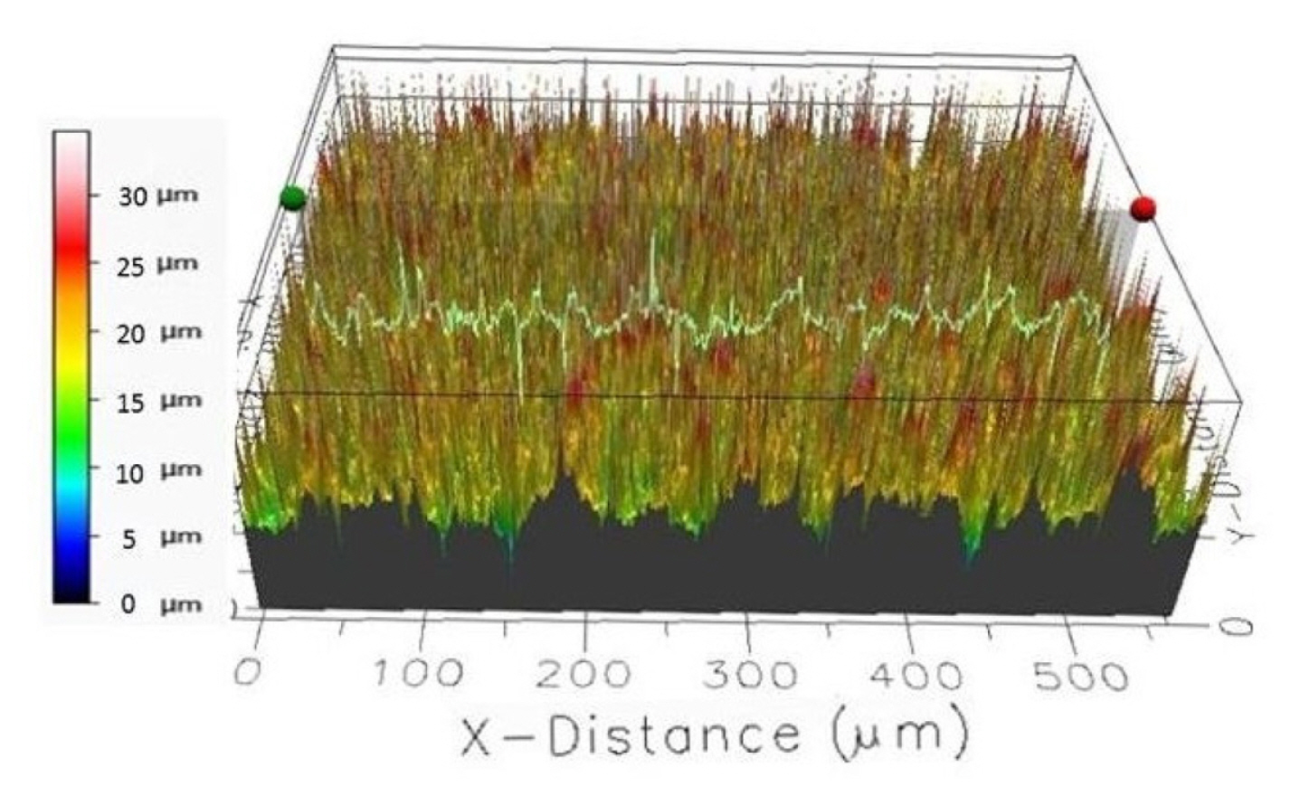
The composite electrodes were characterized by different techniques such as scanning electron microscopy (SEM, Zeiss Supra 40) for surface topology and composition imaging, 2D stylus profilometry (Bruker Dektak XTL) and 3D optical profiling (Filmetrics Profilm 3D/ Model: 205-0792) for analyzing the surface measurements or textures i.e. surface roughness, height variations. In Fig. 5, the surface characterization results of carbon black 1 composite electrode are presented, where the composite ink contains 70% nylon 6,6 and 30% of carbon black 1 particles.
The 2D step height of the nylon electrodes from 6 measurements is on an average 23.66 ± 1.20 μm.
3.4 Blank emission from composite electrodes and the effect of peroxydisulfate as a co-reactant
When hot electron injection into aqueous electrolyte solution is used to excite luminescent labels in bioaffinity assays, it is often beneficial to add peroxydisulfate (S2O82−) as a co-reactant [1–5,23]. Peroxydisulfate reacts near diffusion-controlled rate, producing highly oxidizing sulfate radical in reaction with the hydrated electrons [25]:
The reduction potential of sulfate radical has been reported to be as high as 3.4 V vs. standard hydrogen electrode (SHE) [25]. Thus, when both hydrated electrons and sulfate radicals are present, highly reducing and oxidizing conditions are simultaneously created.
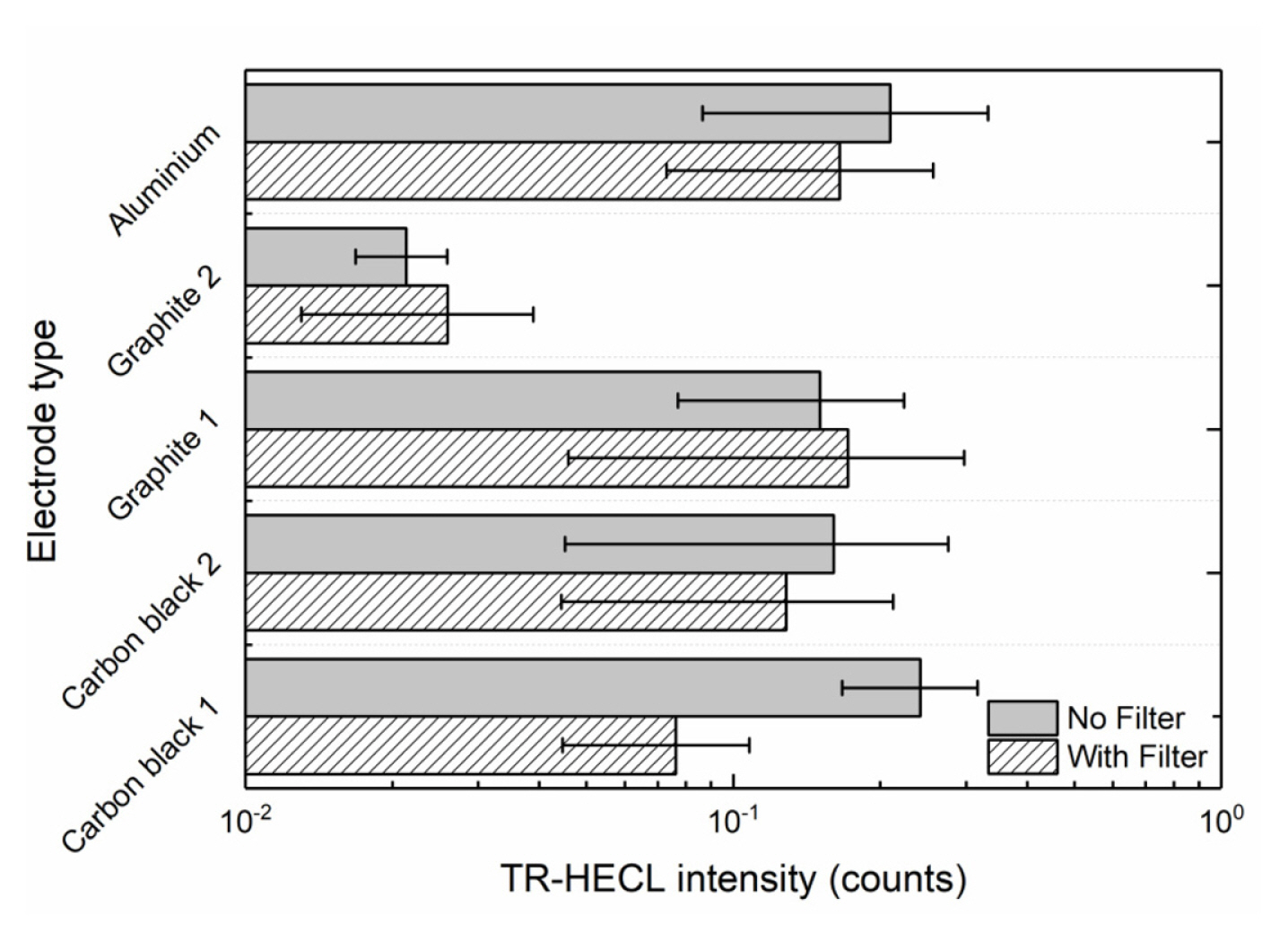
The blank emission in the buffer solution was measured using composite electrodes with maximum emission with Tb (III)-L from Fig. 3. Ten replicates were measured for each of the compositions without any wavelength discrimination and by using 545-nm interference filter (Fig. 7). The blank emission is based on either high field solid state electrochemiluminescence in the insulating nylon 6,6 layer or electrogenerated chemiluminescence at the solidelectrolyte interface. The carbon black 2 as conducting dopant particles produced less blank emission than carbon black 1, when no wavelength discrimination was utilized. However, in the case the composite electrode containing 30 weight % carbon black 1 and 70% nylon 6,6 the blank emission seemed to differ from presently interesting 545 nm more than in case carbon black 2 that allowed the most efficient HECL generation from our Tb (III) chelate beacon. For the sake of comparison, oxide-coated aluminium (0.3 mm thickness; 30 mm width) electrodes were also used in the measurements. Fig. 8 displays that oxide-covered 99.9% aluminium (Merck) shows much stronger background emission during cathodic pulses than any of the presently fabricated composite ink coated electrodes. Thus, if the present electrodes would be used for detection of short-lived emission-displaying organic luminophores the present aluminium brand electrodes would have much poorer performance than composites containing optimal amount of carbon black particles.
3.5 The durability of the electrodes
3.5.1 Stability of composite electrodes during pulse polarization experiments
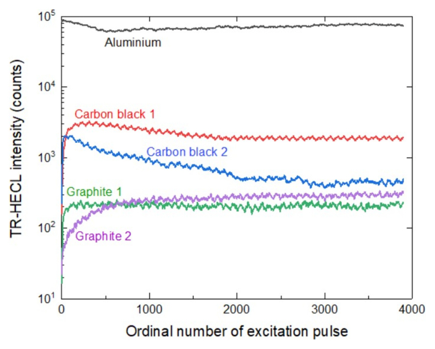
The TR-HECL intensity was followed for 10000 excitation cycles with all the composite electrode types and during this time no destruction of the electrodes were observed and the TR-HECL remained at practically constant level during this time Fig. 9 displays TR-HECL as a function of only the first 4000 ordinal number of excitation pulses for visualization purpose.
From Fig. 9, it can be seen that the performance of the carbon black 1 composite electrode in terms of HECL intensity (photon counts) is the best during cathodic pulse polarization experiments. The durability for graphite 1 and graphite 2 composite electrodes are quite similar. On the other hand, the carbon black 2 composite electrode started to crack.
3.5.2 The effect of pH on TR-HECL in composite electrodes
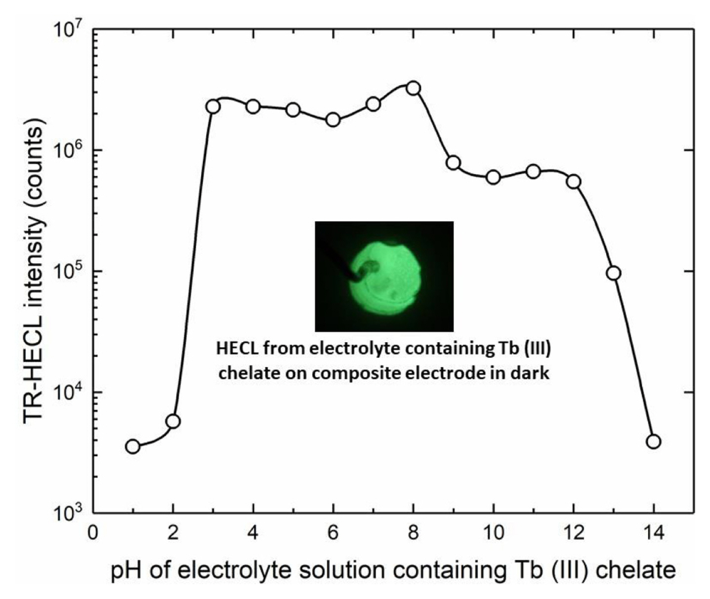
The pH of buffer solutions was adjusted either with sulfuric acid or sodium hydroxide and the HECL intensity was measured as a function of pH of the electrolyte solution. All our multidentate aromatic Tb(III) chelates are decomposed at low pH due to the protonation of the chelating side arms (oxygen and nitrogen in the side arms). Thus, TR-HECL at low pH is due to two reasons. First, decomposition of the chelate, and secondly, conversion of hydrated electrons to atomic hydrogen which is not sufficiently good one-electron reductant for the excitation reactions [4].
On the other hand, at high pH the formation of hydroxo complexes start to decompose the chelate [4]. When the same electrodes used at certain pH were measured again in Tb (III)-L solution at pH 9.2 (borate buffer), each electrode exhibited the same TR-HECL intensity within the reproducibility margins as those electrodes not exposed to the more acidic/alkaline conditions. This indicates that the electrodes tolerated the use of both very low and very high pH solutions without destroying the composite ink coating (Fig. 10).
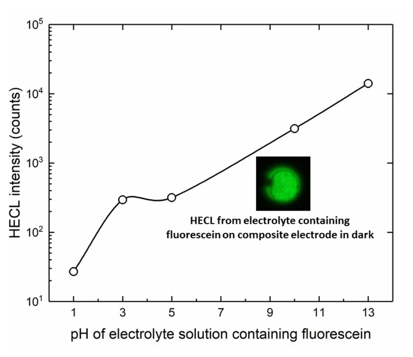
In addition, the effect of pH was also studied by using fluorescein and Ru(bpy)32+ luminophores as depicted in Fig. 11 and Fig. 12 respectively. In principle, both red-ox and red-ox excitation routes are possible for fluorescein on thermodynamic grounds, but we have earlier found evidence that the ox-red route is again the predominating excitation pathway for this luminophore [19]. The results with fluorescein clearly showed that the present composite electrodes work well at highly basic solutions with luminophores able to emit HECL at highly alkaline conditions.
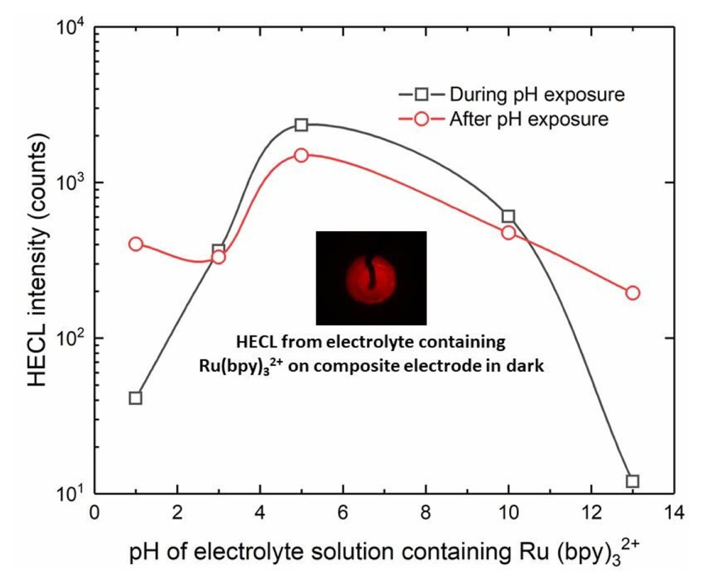
In the case of Ru(bpy)32+, the measurement with the same electrode was again repeated at pH 9.2 (borate buffer) after measurement at certain specific pH (Fig. 12). Ru(bpy)32+ is excited almost solely by ox-red mechanism since its one-electron reduced form is very unstable in aqueous solution and is disintegrated. On the other hand, one-electron oxidized form of the chelate has a long lifetime in aqueous solution and therefore gives a good steppingstone for excitation reaction by hot/hydrated electrons [23].
Thus, all the molecular probes/beacons presently applied in the absence of peroxydisulfate ions are first one-electron oxidized by hydroxyl radicals generated from dissolved molecular oxygen followed by the excitation step by hot/hydrated electron [5].
The metal-to-ligand excited triplet state is always the emitting species in case of Ru(bpy)32+, regardless whether the excited state first formed in electron transfer excitation step is metal to ligand excited singlet state (1MLCT*) or metal to ligand charge transfer excited triplet state (3MLCT*). If the 1MLCT* is initially formed intersystem crossing occurs and 3MLCT* is obtained which finally emits light [23,39]. Unfortunately, the luminescence lifetime of 3MLCT* emission is too short to be utilized for TR-HECL measurements due to the time constants of the present instrumentation and the present electrolytic cells.
The Ru(bpy)32+ measurements also showed that the present composite electrodes did tolerate the use both in highly acidic, or basic conditions. However, the repeated measurements in normal buffer solution (pH 9.2) following the pH treatment/exposure showed that the composite electrodes were still usable after the use at extreme conditions.
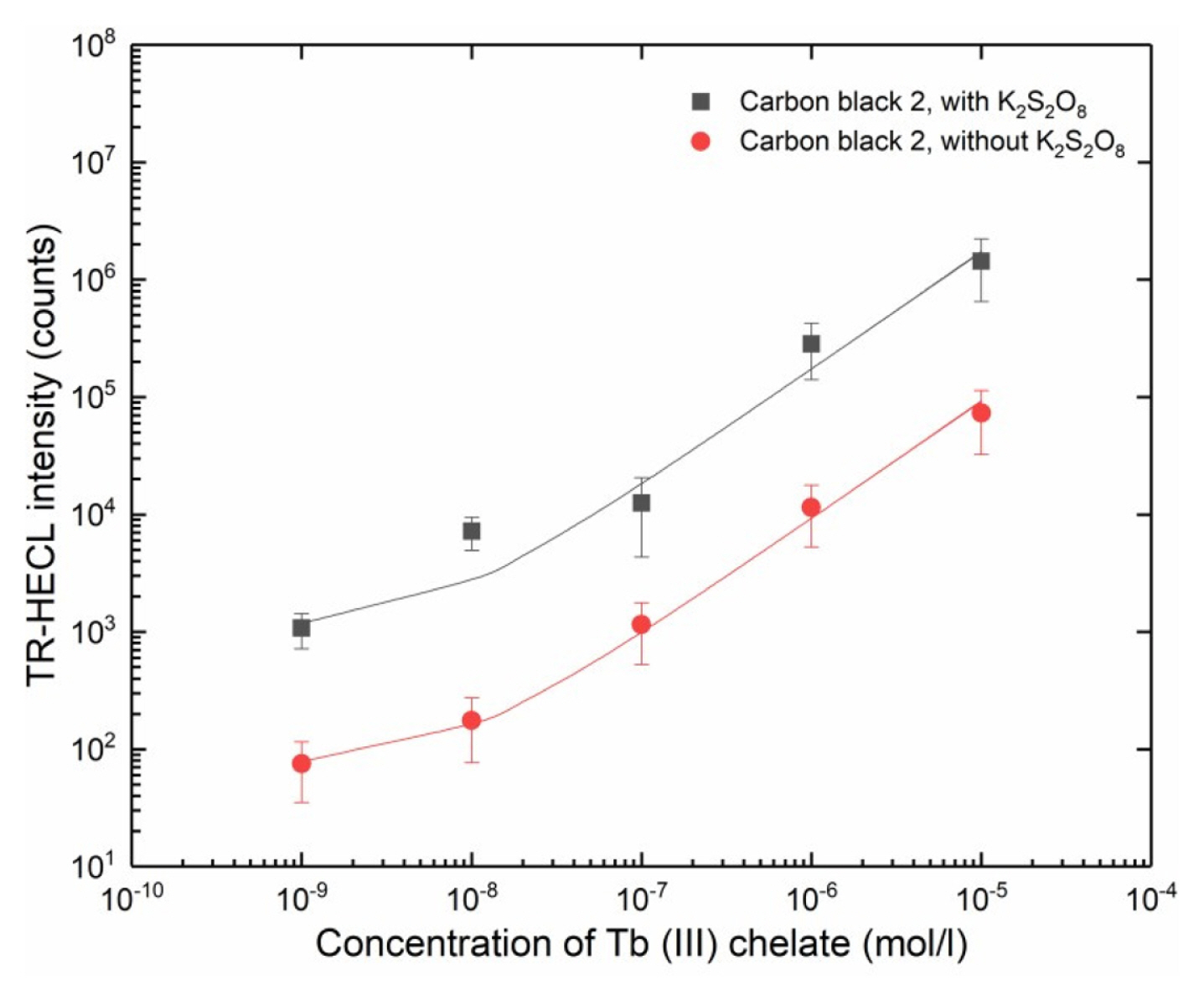
3.6 Analytical applicability of the nylon 6,6 composite electrodes
The composite film containing 30% of carbon black 2 exhibited the highest TR-HECL intensity (Fig. 3). Thus, the analytical applicability of nylon 6,6, composite electrodes doped by carbon black 2 particles was studied by measuring TR-HECL calibration curves of Tb (III)-L, both in the absence and presence of peroxydisulfate ions. Linear calibration plots spanning over several orders of magnitude of Tb (III)-L concentration were obtained (Fig. 13). Thus, the electrodes can be used e.g. in bioaffinity assays utilizing Tb (III) chelate labels.
3.7 Electron transfer through the composite film
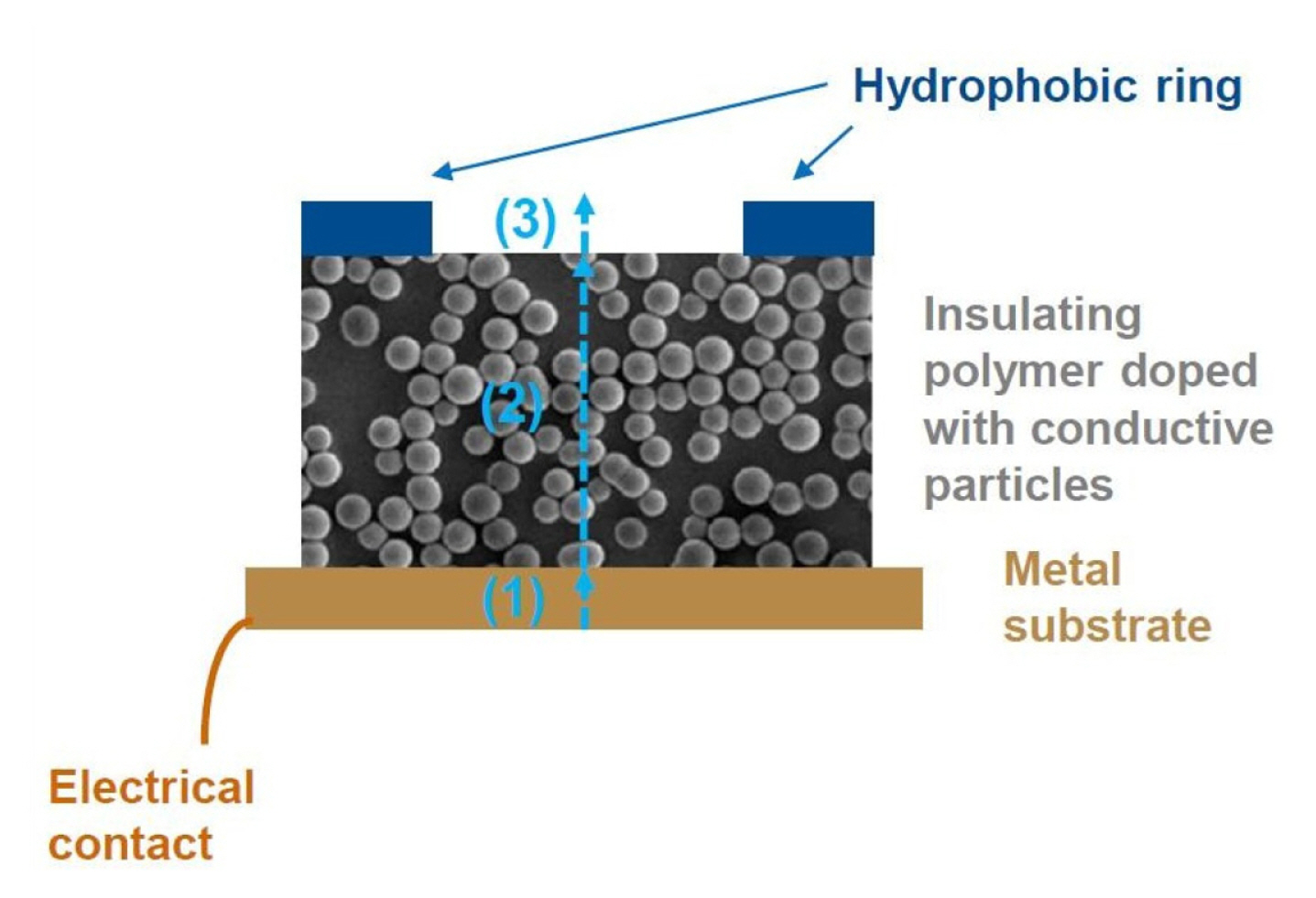
We assume that current transport through the composite layers has three steps: (1) current injection from metal to composite layer, (2) current transport in the composite layer by resonance tunneling and (3) current injection to the electrolyte solution (Fig. 14). The electron injection to the composite film can be based on the direct contact of carbon particles to the base metal, but part of the current is in all likelihood produced by tunneling mechanism variants to the particles inside of the polymer matrix but in close proximity of the metal interface.
Inside the composite film the electrons are transported via carbon particles mainly by resonance tunneling [40,41] and field-assisted direct tunneling [42] and, finally, electrons are injected into the aqueous electrolyte solution by field-assisted direct tunneling or field emission [43] from the carbon particles located at the surface of composite films. This step is still under investigation in our lab, but for many practical purposes it is not important whether the hot electron injection is based on the direct field-assisted tunnel emission or field emission from the composite electrode.
Usable cell for HECL measurements can be achieved simply by dispensing a suitable volume of studied solution inside the hydrophobic ring (Fig. 14) and putting e.g. an ITO-glass anode or alternatively a plastic sheet coated with carbon nanotubes as an anode on top of the hydrophobic ring acting as a spacer that defines the volume of the cell with its thickness together with the circle area inside the hydrophobic ring. In this way the light emission can be measured through optically transparent anodes.
4. Conclusions
The novel field of hot electron electrochemistry is presently largely unexplored. The most significant differences with traditional aqueous electrochemistry at active electrodes are: (1) the stability limits of water can be exceeded, (2) one electron reductions can be made in situations where traditional electrochemistry leads to concerted two-electron transfers, and (3) the reductions can be made of the distance at least several tens of nanometers away from the electrode thus allowing e.g. efficient excitation of labels in immunometric immunoassays. The present composite material withstanding a very wide pH range and many types of solvents allows the production of robust composite electrodes for injection of hot electrons (i) into aqueous solutions, and (ii) also into many other solvents or solvent mixtures due to the good chemical durability of nylon 6,6. Hot- and hydrated/solvated electrons can be easily obtained with these electrodes in any laboratory to induce various one-electron reductions in aqueous solutions not obtainable at active metal electrodes on the basis of traditional electrochemistry. For instance, metal ions at unusual oxidation states not obtainable at active metal electrodes can be created at the present composite electrodes as in the case in pulse radiolysis [24], many types of luminophores can be excited by reaction cycles involving one-electron redox steps [1–5]. Different types of organic pollutants can be disintegrated by hot and hydrated electrons [5,32,44–46]; also some specific organic synthesis can be carried out with hydrated electrons [47]. Moreover, bacteria can be exterminated by introducing hot and hydrated electrons in an aqueous media needing disinfection [27,29,48]. All in all, several promising application fields seem to exist where the present electrodes could be utilized.