Operational Characteristics of High-Performance kW class Alkaline Electrolyzer Stack for Green Hydrogen Production
Article information
Abstract
Polymer electrolyte membrane (PEM) electrolyzer or alkaline electrolyzer is required to produce green hydrogen using renewable energy such as wind and/or solar power. PEM and alkaline electrolyzer differ in many ways, instantly basic materials, system configuration, and operation characteristics are different. Building an optimal water hydrolysis system by closely grasping the characteristics of each type of electrolyzer is of great help in building a safe hydrogen ecosystem as well as the efficiency of green hydrogen production. In this study, the basic operation characteristics of a kW class alkaline water electrolyzer we developed, and water electrolysis efficiency are described. Finally, a brief overview of the characteristics of PEM and alkaline electrolyzer for large-capacity green hydrogen production system will be outlined.
1. Introduction
The construction of large-scale power generation facilities inevitably comes with the cost issues of construction and maintenance [1]. It is especially for transmission and distribution lines and substation facilities when the locations of electricity source and demand are different. In addition, considering 40% power generation efficiency and 6% transmission loss, Republic of Korea, which has a high proportion of primary energy imports, needs to diversify energy sources, and efforts to increase the proportion of renewable energy generation are continuing to keep pace. However, since renewable energy such as wind or solar power generation has the fluctuation problems depending on weather and climate, it causes electric power system instability when renewable energy connection is increased. Therefore, it is very important to utilize an appropriate Energy Storage System (ESS) when considering output fluctuations and frequency adjustment due to the intermittentness of renewable energy generation. The energy density and power density characteristics of the applicable energy conversion devices, which can be checked in a Ragone plot, must be carefully examined to use it practically as an ESS [2]. Supercapacitors have sufficient output power density that can be used as an ESS for both alternating current (AC) frequency regulation and electric power system stability, but it is difficult to achieve high capacity, so when applying large capacity, there is a serious cost problem. ESS based on lithium-ion secondary batteries (LIB) must solve both cost and safety problems at the same time. Unfortunately, current LIB R&D is mostly focused on the realization of high capacity only. Although some of the so-called low tortuosity cell (LTC) research is being conducted for the development of high-output LIB capable of rapid charging and discharging, but the industrial manufacturers are hesitant to apply these technologies into mass production due to problems of manufacturing cost and selling price.
Producing hydrogen through water electrolysis using expensive renewable energy power and using it again for fuel cell power generation is low in efficiency. So, economic feasibility of green hydrogen is clearly low at the current level. Therefore, tremendous efforts are required to secure the price competitiveness of both water electrolyzer and fuel cell. These are along with the hydrogen production efficiency of the water electrolyzer and the simultaneous utilization of electricity and heat energy of the fuel cell [3].
The alkaline electrolyzer utilizes cost-competitive Ni or stainless steel, not a noble metal (Platinum group metals, PGMs) electro-catalyst which is commonly required for polymer electrolyte membrane (PEM) water electrolysis [4,5]. However, it has a drawback that the operating current density (~0.4 A/cm2) is lower than that of PEM electrolyzer (~2.0 A/cm2), which increases the device volume, and is unfavorable for slow start/stop response, high pressure, and differential pressure operation [6,7]. In addition, operational characteristics of alkaline electrolyzer may not be suitable with the connection to the renewable energy power. It may cause unexpected problems such as durability and efficiency degradation in alkaline water electrolysis devices developed in the existing rated output operation mode.
In this study, basic operational studies are conducted for the development of high-performance kW class alkaline electrolyzer and we would like to consider how to utilize an alkaline electrolyzer for the green hydrogen production further.
2. Experimental
Fabrication and Performance Tests of kW-class Alkaline Electrolyzer. The kW-class alkaline electrolyzer stack consists of a total 5-unit cells. The unit cell is a circular cell with a diameter of 16 cm. The electrode is made of a Ni-based alloy foam and a commercial porous separator (Zirfon Perl UTP 500, AGFA), and it is designed to have a current density of 300~500 mA/cm2 at 1.8V. A 30 wt% KOH aqueous solution is used as the electrolyte solution. The evaluation is performed by using CNL Energy’s dedicated alkaline electrolyzer evaluation station which has a power supply of 20 V, 76 A.
3. Results and Discussion
Basically, the production of green hydrogen using water electrolysis is to produce hydrogen and oxygen by electrolyzing water through the reverse reaction of the fuel cells [8,9]. The water electrolyzers capable of producing hydrogen include polymer electrolyte membrane (PEM), alkaline anion exchange membrane (AEM), and alkaline electrolyzer [10–12]. In addition, there is a solid oxide electrolytic cell (SOEC) through the reverse reaction of a solid oxide fuel cell (SOFC) that can operate at 600 to 800°C [13]. In particular, the PEM electrolyzer is environmentally friendly and can produce high purity hydrogen. Since a huge gas-liquid separator is not required for a dry cathode way of hydrogen production, a simple system design is possible through a simple balance of plant (BOP). Simple design, high current density, and fast response are advantages of a PEM electrolyzer, but the use of both expensive noble Platinum group metals (PGMs) electro-catalyst and fluorine-based perfluorosulfuric acid (PFSA) membranes is a distinct disadvantage. Therefore, for the practical development of PEM electrolyzer, there is a need for research and development related to durability to reduce cost and maintain electrolyzer efficiency. In case of an alkaline electrolyzer, a direct current (DC) power source is applied to the electrode to generate oxygen through an oxidation reaction at the anode and hydrogen through a reduction reaction at the cathode in the reaction of alkaline water electrolysis. At this time, hydroxide ions (OH−) are transferred pass through an aqueous potassium hydroxide (KOH) electrolyte solution to complete the entire electrolysis circuit. It is an advantage that the alkaline electrolyzer uses a low-cost electrode such as Ni compared to the PEM electrolyzer. However, it is still necessary to solve the problem of mixing hydrogen and oxygen due to the high-pressure operation, and pressure difference between negative and positive electrode. In addition, since the generated hydrogen or oxygen is inevitably mixed with the KOH solution and discharged, the role of a gas-liquid separator for separating them is quite important at an alkaline water electrolysis system. Accordingly, the alkaline electrolyzer has a low current density (~0.4 A/cm2), so it is difficult to design a simple system compared to a PEM electrolyzer because the size of the stack must be large to meet the production of hydrogen, and the role of a BOP such as a gas-liquid separator is also important.
First, if we are looking at the activation process for maximizing the initial performance of an alkaline electrolyzer, this is very simple compared to a PEM electrolyzer, PEMFC, or LIB. Looking at the difference between the alkaline electrolyzer and other electrochemical energy conversion storage devices, the general alkaline electrolyzer does not follow the slurry-based electrode manufacturing process and uses a porous separator. In the case of LIB, the cell is completed using a polyolefin-based porous separator (polyethylene (PE) or polypropylene (PP)), a slurry-based negative/positive electrode and the mostly carbonate-based organic electrolytes (ethylene carbonate (EC), propylene carbonate (PP), propyl propionate (PP), and so on). LIB takes a long time in the primary charging/discharging process called activation process after assembling the stack cell and impregnating the electrolyte, which is a heavy burden on the industrial manufacturer. PEMFC or PEMEC is easier than LIB, but requires a more difficult cell activation step than alkaline electrolyzer. When a thick electrolyte membrane is used or when the electrode density is high and porosity is low, consideration should be given to the selection of an activation process that can optimize the initial performance of the electrolyzer. Anyway, the alkaline electrolyzer has a macro-level pore structure in both electrode and separator, and since OH− ions are directly transferred through the electrolyte solution, it does not seem necessary to consider the formation of a so-called three-phase boundary interface. However, it is necessary to examine the wettability of KOH electrolyte solution at the pore structure in the electrodes and separator. If the compatibility such as solubility parameter (cal1/2cm−3/2, J1/2 m−3/2) between the electrolyte solutions, the electrode, and the separator is not appropriate, there is a possibility that the performance of the electrolyzer is deteriorated due to air condensation in the pores under operating conditions such as KOH flow rate (cc per minute) and high pressure back pressure (bar).
Fig. 1 shows an example of an electrochemical protocol during the activation process of a PEM electrolyzer and an alkaline electrolyzer. In the case of an alkaline electrolyzer, you can check the performance of the electrolyzer after repeating voltage cycling from 2.0 to −2.0V. It can be seen that the electrolyzer performance has reached its peak even after repeating this voltage cycling approximately 10 to 20 times. The PEM electrolyzer can repeat the process of applying about 10 seconds per voltage with an increment voltage of 0.1 V from a low voltage near the onset voltage of the oxygen generation reaction to 2.0 or 2.1 V using a voltage step. At this time, as described above, when a thin electrolyte membrane and an electrode with high porosity are used, the number of repetitions of the process may be low. However, when Nafion 115 or more thick electrolyte membranes, thick electrodes, high loading electrodes, and low porosity electrodes are used, a new strategy is needed to increase the number of repetitions of the process or shorten the activation.

Electrochemical cell break-in or activation protocol for (a) alkaline electrolyzer and (b) PEM electrolyzer.
Fig. 2 shows the i-V performance of kW class alkaline electrolyzer stack. Unfortunately, the current limit of the power supply of the stack test station that we have is only 76 A, so the maximum stack power is measured to be about 700 W. However, if the current limit is over 100 A, it is expected that at least 1 kW or more of stack power will be measured. A current density close to 0.4 A/cm2 is confirmed at about 2.0 V based on the unit cell voltage. At this time, the power density is approximately 700 to 800 mW/cm2. In order to accurately measure the efficiency of the stack, instantly, the amount of hydrogen produced per unit time must be accurately measured. However, in this experiment, both hydrogen and oxygen produced through the electrolyzer are discharged into the atmosphere due to the safety issue of evaluating the safe electrolyzer and where to use the produced hydrogen. In order to check the deviation between cells, each cell voltage was checked after applying a stack voltage of a constant voltage. Since bipolar cells such as fuel cells, electrolyzers, and all-solid-state battery are connected in series with each other, the current is the same for each cell, but the voltage may be different. The difference in cell voltage was not significant until the stack voltage as low as 8.5 V. The number of cells in the alkaline electrolyzer stack used in this study is 5, which does not have a significant parameter in statistical analysis such as Six Sigma. However, when the stack voltage is 9.0 V (1.8 V cell voltage), it can be seen that the size of the box plot is large compared to the low voltage in Fig. 2(c). It is expected that the generation of hydrogen and oxygen increased at high voltage and the dispersion of the voltage distribution increased. In order to check not only the durability of the electrolyzer, but also the safety of renewable energy-linked hydrogen production, it is necessary to utilize the accelerated stability test (AST) protocol based on the characteristics of wind power or solar power generation. In the long-term performance evaluation where the intermittent of renewable energy is applied in a short period of time using the AST protocol, there is a need for additional studies on the performance deviation of each stack and cell, the flow and concentration of hydrogen and oxygen, and the stack efficiency. Anyway, after applying 1.4, 1.5, 1.6, 1.7, 1.8 V based on the unit cell voltage (7.0, 7.5, 8.0, 8.5, 9.0 V based on the stack cell voltage) for 30 minutes for each voltage, production rate of hydrogen is measured, and it is applied to evaluate the stack efficiency (%) in Fig. 3. The water electrolysis efficiency of the alkaline electrolyzer was calculated as the ratio of the amount of hydrogen generated to the total amount of power input. As a result, the stack efficiency of about 75 to 80% can be obtained at 1.7 V of the single cell voltage. Converting the hydrogen production rate of 510~600 ccm is approximately 0.03~0.035 Nm3/hr, and it translates to 0.11~0.12 kW. At this time, through the applied stack voltage of 8.5 V and a current of 17.3 A, the amount of power applied to the electrolyzer stack can be calculated as about 0.15 kW. Accordingly, the water electrolysis efficiency is approximately 78~84%.
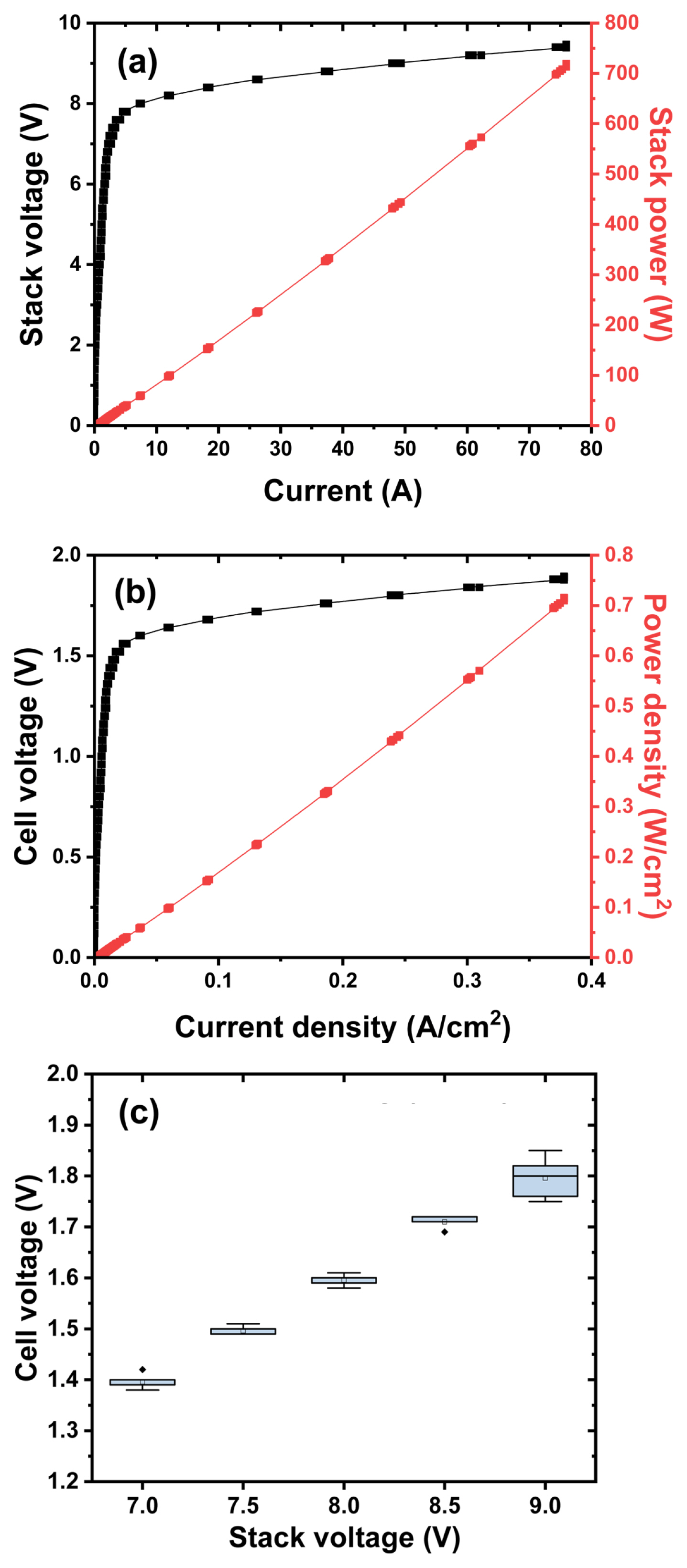
(a) Raw and (b) normalized i-V and power performance of kW-class alkaline electrolyzer. (c) Box plot of the cell voltage for each cell constituting an alkaline electrolyzer stack.

(a) Measured current and (b) flow rate of produced hydrogen and oxygen gas after applying voltage step.
One of the main factors affecting the output power characteristics of the electrochemical energy conversion storage device is the mobility of ions, which act as a mediator for charge transfer. Examples include H+ of PEMFC and PEMEC, O2− of SOFC, OH− of alkaline fuel cells and electrolyzers, and Li+ of lithium-ion batteries. For lithium-ion secondary batteries, which have been undergoing research and development of energy density improvement mostly, new research and development on output power characteristics is attracting attention to improve user convenience and safety. Numerous attempts being made for this are how the battery conducts electricity well and ions flow well. From this perspective, the issue of alkaline water electrolyzer is confirmed. First of all, in order to match the same hydrogen production, an electrolytic cell stack having the same size of 5 times or more is required by simple arithmetic calculation compared to a PEM electrolyzer. This can be expected that the length of the path through which electricity and ions must be conducted is much longer in the alkaline electrolyzer compared to the PEM electrolyzer. One way to improve the output characteristics of an alkaline electrolyzer is to make the cell structure zero-gap. It is known that this greatly improves the load tracking ability of an alkaline electrolyzer, but it is still inferior when compared to a PEM electrolyzer. Combining the above results, it can be expected that the characteristics of a PEM electrolyzer and alkaline electrolyzer are complementary to each other when the system is configured in a hybrid form. PEM electrolysis technology, which has a fast response characteristic and a wide operating range, is suitable for linking the power system with a high occupancy rate for the output variability and intermittent renewable energy [14]. In order to respond to the discrepancy between the supply and demand of the power system due to the connection of renewable energy for a long time, the alkaline water electrolysis technology, which has high technology maturity and capable of producing large amounts of hydrogen, will be more suitable. Through the technology development of a hybrid electrolysis integrated system linking a PEM and an alkaline electrolyzer, a wide range of renewable energy can be used, as well as a long-term response to the inconsistency between the supply and demand of the power system. By developing MW-class PEM and alkaline electrolysis stacks and systems, and configuring them as hybrid systems, it will be possible to convert and produce unused power from renewable energy into hydrogen.
4. Conclusions
A circular cell having a diameter of 16 cm is prepared using a Ni-based electrode and a commercial porous separator, and a kW-class alkaline electrolyzer composed of 5 cells is prepared to evaluate its performance characteristics. A current density of 0.4 A/cm2 is confirmed at about 2.0 V based on a single cell voltage, and the stack efficiency of hydrogen production found at 1.7 V is about 78~84% level. It is possible to check the delay time of about 2~3 seconds when applying the step voltage. Through this, it can be concluded that the alkaline water electrolysis technology, which has high technology maturity and capable of producing large-capacity hydrogen, is suitable for a long-term response to the inconsistency between supply and demand of the power system due to the connection of renewable energy. However, it is still necessary to take close look against the possibility of mixing hydrogen and oxygen gas due to the high-pressure operation and the pressure imbalance between the hydrogen and oxygen electrode because of the use of the porous membrane.
Acknowledgments
This research was supported by the Korea Institute of Energy Technology Evaluation and Planning funded by the Korea government MOTIE (2019281010007A)