1. Introduction
An increased interest in environmental issues has resulted in extensive efforts to reduce the consumption of fossil fuels for energy generation. As a part of this effort, electric vehicles (EVs) which can replace conventional combustion engine vehicles have attracted considerable attention. Currently, lithium ion batteries (LIBs) are essential components that supply energy to electric vehicles and determine their mileage. Therefore, the development of enhanced LIBs is important to determine the commercial success of EVs. Over the past several decades, the energy density, rate capability, and cyclic performance of LIBs have been greatly improved because of extensive research [1–7]. However, the flammable liquid electrolyte used in LIBs remains a threat to safety. In particular, an electric vehicle using large-scale LIBs can significantly impact the consumer’s choice because of the safety issues. The fundamental solution to this problem is the use of nonflammable solid electrolytes instead of organic liquid electrolytes [8–15]. Until now, many inorganic materials have been explored as the potential solid electrolytes for batteries. Among them, sulfides have been considered as the most promising candidates for solid electrolytes because of their high ionic conductivity and good ductility [16–21]. However, the sulfides are extremely reactive leading to undesirable side reactions with oxide cathodes [22–24]. Therefore, controlling the interfacial reactions between the sulfide electrolyte and cathode is essential to commercialize all-solid-state cells (ASSCs) based on sulfide electrolytes.
To reduce the interfacial reactions, it is necessary to select a solid sulfide electrolyte with low reactivity, since the sulfides reacting sensitively with oxide cathodes cannot be used as the solid electrolytes for battery systems. Moreover, the surface coating of cathodes with a stable material is required to reduce the interfacial reactions. Several materials such as Li2O-SiO2, Li3xLa2/3–xTiO3, and LiNbO3 have been used as the coating materials to suppress the undesirable side reactions and enhance the electrochemical properties of all-solid-state cells (ASSCs) [25–28]. However, studies regarding the surface coating of cathodes against sulfide electrolytes are still in their initial stages.
In this study, we observed the electrochemical properties of ASSCs using one cathode and three types sulfide electrolytes. Despite using the same cathode (Li[Ni0.8Co0.15Al0.05]O2), the electrochemical performance of ASSCs varied significantly according to the type of sulfide electrolyte. This process was useful to identify a suitable sulfide electrolyte which exhibited low reactivity with oxide cathodes. Pulverized sulfide electrolyte was also used to improve the physical contact between the cathode and electrolyte.
Furthermore, the surface of cathode was coated using Li2MoO4-LiI to suppress the undesirable interfacial reactions. Li2MoO4 was successfully used to coat the cathodes for sulfide-based ASSCs [17]. Addition of LiI has been reported as a useful approach for enhancing the rate capability of ASSCs [15]. A combination of Li2MoO4-LiI coated cathode and a suitable sulfide electrolyte is expected to offer much enhanced electrochemical performance of ASSCs than that of a pristine cathode and unfavorable sulfide electrolyte.
2. Experimental
2.1 Preparation of solid electrolytes
To prepare the argyrodite (Li6PS5Cl) electrolyte, lithium sulfide (Li2S, Alfa), phosphorus pentasulfide (P2S5, Aldrich), and lithium chloride (LiCl, Aldrich) were mixed by mechanical milling and heated at 550°C for 3 h. The 75Li2S–22P2S5–3Li2SO4 electrolyte was synthesized from lithium sulfide (Li2S, Alfa), phosphorus pentasulfide (P2S5, Aldrich), and lithium sulfate (Li2SO4, Aldrich) using the same milling and heating process (215°C, 3 h). The Li7P3S11 electrolyte was prepared by a mixture of lithium sulfide (Li2S, Alfa) and phosphorus pentasulfide (P2S5, Aldrich) (molar ratio = 7: 3). This mixture was also subjected to mechanical milling and subsequent heat treatment (300°C, 2 h). The prepared argyrodite was pulverized using mechanical milling to reduce the particle size [28]. Initially, the argyrodite electrolyte was dispersed in anhydrous heptane (99%, Sigma-Aldrich) and anhydrous dibutyl ether (99.3%, Sigma-Aldrich) solution. Then, the mixed solution was placed in a ZrO2 jar with ZrO2 balls (3-mm diameter). Milling was conducted at 200 rpm for 24 h, and the powder was dried at 120°C. The ionic conductivities of these electrolytes were ~ 2.5 mS·cm−1 (argyrodite), ~ 1 mS·cm−1 (75Li2S–22P2S5–3Li2SO4), ~ 3 mS·cm−1 (Li7P3S11), and ~ 1 mS·cm−1 (pulverized argyrodite), respectively.
2.2 Preparation of electrode material
Pristine Li[Ni0.8Co0.15Al0.05]O2 (NCA) powder was supplied by the Research Institute of Industrial Science and Technology (RIST). In order to prepare the coating solution, lithium nitrate (LiNO3, Aldrich) and phosphomolybdic-acid (HPMO) solution (H3[P(Mo3O10)4], 20 wt% in ethanol) were dissolved in anhydrous ethanol (99.9%, Aldrich) at 80°C. The amount of coating material was adjusted to 0.5 wt% of the pristine powder. As LiI sources, lithium nitrate and ammonium-iodide (NH4I, Aldrich) were also dissolved in the prepared coating solution (0.25 mol % to the molar ratio of Li2MoO4). Then, the NCA powder was added to the coating solution. The mixed solution was stirred and evaporated at 80°C. The dried materials were ground and heat treated at 600°C for 2 h under air atmosphere. After the mixture was ground to room temperature, the Li2MoO4-LiI coated NCA powder was obtained.
2.3 Material characterization
To identify the pristine and Li2MoO4-LiI coated NCA powder, the X-ray diffraction (XRD, Bruker D8) patterns of the samples were obtained over 2θ range of 5–120° with monochromatized Cu-Kα radiation (λ = 1.5406 Å). Highscore software was used for the X-ray Rietveld refinements. Field emission-scanning electron microscopy (FE-SEM, Nova Nano 200) was used to observe the surface shapes of the pristine and surface-coated powders.
2.4 ASSCs fabrication
Electrochemical performance tests were conducted using 2032-type coin cells. The cathode mixture for composite electrode was prepared by mixing the cathode (pristine or Li2MoO4-LiI coated NCA powder), sulfide solid electrolyte, and carbon black (super P) at a weight ratio of 70: 30: 2. The electrolyte layer was obtained by compressing 0.2 g of the sulfide electrolytes under 30 MPa pressure in a mold with a diameter of 16 Φ. Subsequently, 0.02 g of the prepared cathode composite was pressed (30 MPa) on the separator and a carbon nanotube paper (Hanwha Chemical) was attached on top of the pellet. After that, 0.05 g of Li-In powder was also pressed (30 MPa) on the other side of the pellet as the anode. The compressed pellets were fabricated into 2032 coin-type cells. To test the electrochemical performance, they were subjected to galvanostatic cycling (WonATech system) in a voltage range of 3.88–2.38 V. The voltage window was determined by considering the voltage drop attributed to the Li-In anode. The impedances of the ASSCs were measured using an electrochemical workstation (AMETEK, VersaSTAT 3) by applying an AC voltage with an amplitude of 10 mV over a frequency range of 0.01 Hz–100 kHz.
3. Results and Discussion
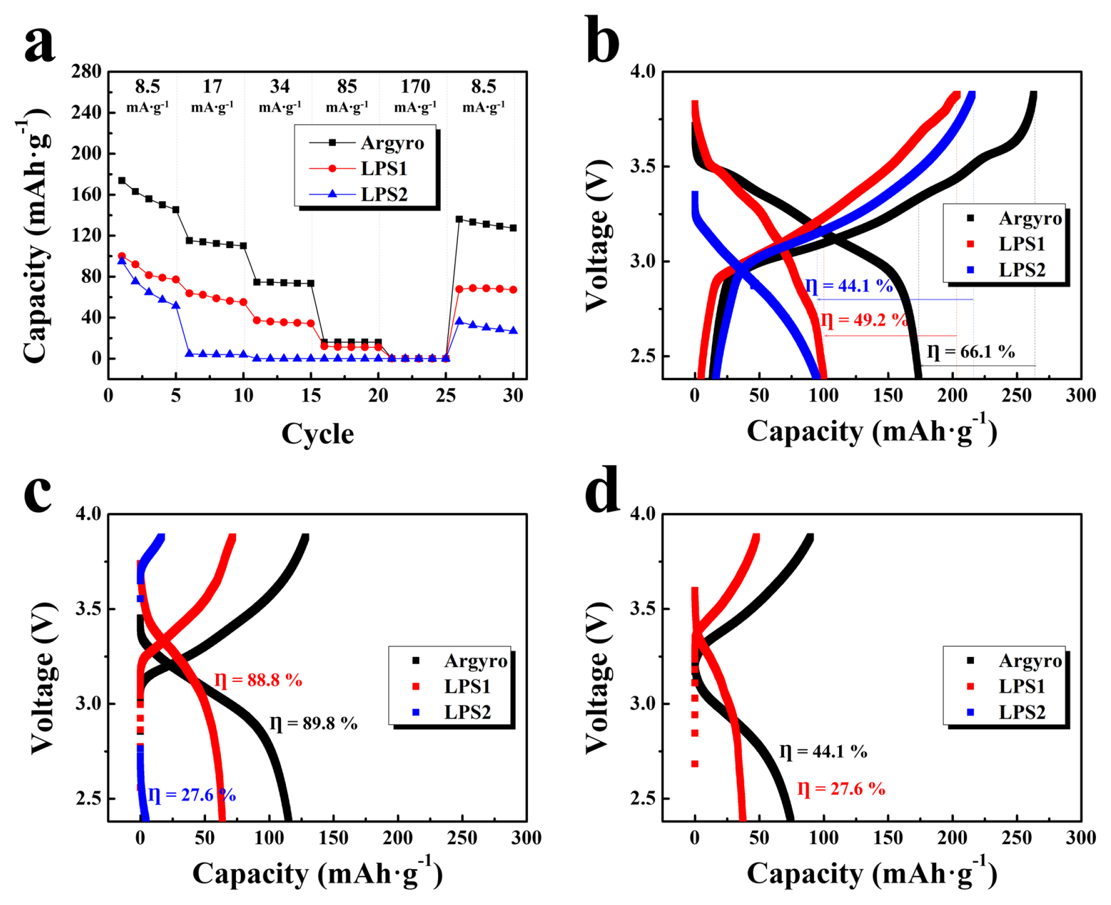
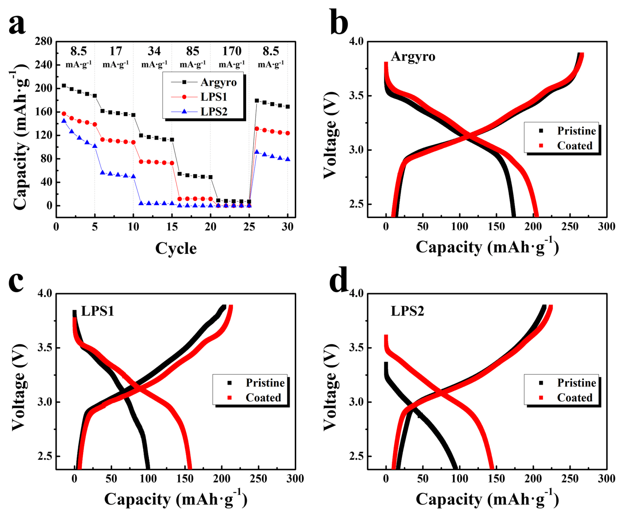
The electrochemical performance of ASSCs containing NCA (Li[Ni0.8Co0.15Al0.05]O2) cathode and tree types of sulfide electrolytes were observed to analyze the effect of electrolytes. For convenience, the argyrodite, 75Li2S-22P2S5-3Li2SO4, and Li7P3S11 electrolytes are named as Argyro, LPS1, and LPS2, respectively. Fig. 1a shows the discharge capacities of the cells at current densities of 8.5, 17, 34, 85, and 170 mA·g−1 in the voltage range of ~ 3.88–1.88 V. Even though the same cathode was used, the capacities of the cells varied significantly depending on the type of sulfide electrolyte. At a current density of 8.5 mA·g−1, the initial capacity of the cell containing Argyro as the electrolyte was ~ 174 mAh·g−1. However, the cells containing LPS1 and LPS2 as electrolytes were ~ 100 and ~ 95 mAh·g−1, respectively. As the current density increased, the capacities of all cells decreased. At all current densities, the cell containing Argyro exhibited superior capacity than the cells containing LPS1 and LPS2. However, the capacity of the cell containing Argyro was also dropped to almost zero at a current density of 170 mA·g−1. Considering that 170 mA·g−1 is just ~ 1 C rate, and the capacity reduction of the cells containing liquid electrolyte is not so critical at 1 C rate, the rate capability of ASSCs is significantly inferior to that of the commercial LIBs. This is largely associated with the side reactions at cathode/sulfide electrolytes and the contact instability between electrodes and solid electrolytes [29].
Fig. 1b–d show the voltage profiles of the cells containing the three types of electrolytes. As seen in Figure 1b, the cell containing Argyro exhibited much higher Coulombic efficiency (~ 66%) than the cells containing LPS1 (~ 49%) and LPS2 (~ 44%) at 8.5 mA·g−1 (initial cycle in Fig. 1a). At 17 and 34 mA·g−1 (6th and 11th cycle in Figure 1a), the capacity of the cells containing LPS1 and LPS2 rapidly decreased. The retained capacity of the cells at 34 mA·g−1 and 8.5 mA·g−1 is only ~ 37% (LPS1) and ~ 0% (LPS2). The cell containing Argyro also exhibited decreased capacity at high current densities. However, capacity, Coulombic efficiency, and capacity retention were superior compared to the cells containing LPS1 and LPS2. The discharge capacity, capacity retention, and Coulombic efficiency (η) of the cells containing the three types of electrolytes are summarized in Table 1.
The lower capacity of the cells containing LPS1 and LPS2 than the cell containing Argyro may mean that the undesirable side reactions between the oxide cathode and electrolyte are severe when LPS1 and LPS2 are used. The ionic conductivity of LPS1 (~ 1mS·cm−1) is slightly lower than that of Argyro (~ 2.5mS·cm−1), which also affects the electrochemical performance of the cells containing LPS1. However, the ionic conductivity of LPS2 (~ 3 mS·cm−1) is slightly higher than that of Argyro. Thus, the capacity drop of cells containing LPS2 is mostly attributed to the side reactions. The Argyro may be relatively less reactive with oxide cathodes, which reduces the side reactions with the cathode. Nevertheless, as shown by the much inferior rate capability compared to the conventional LIB, the interface between the cathode and sulfide electrolyte appears to be critically unstable.
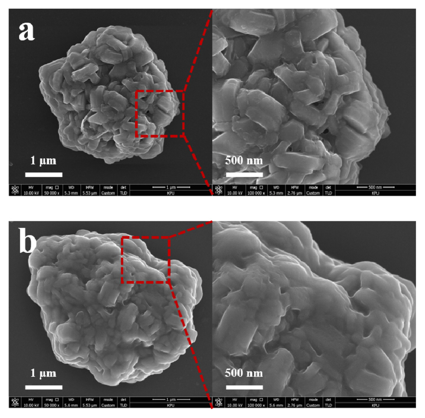
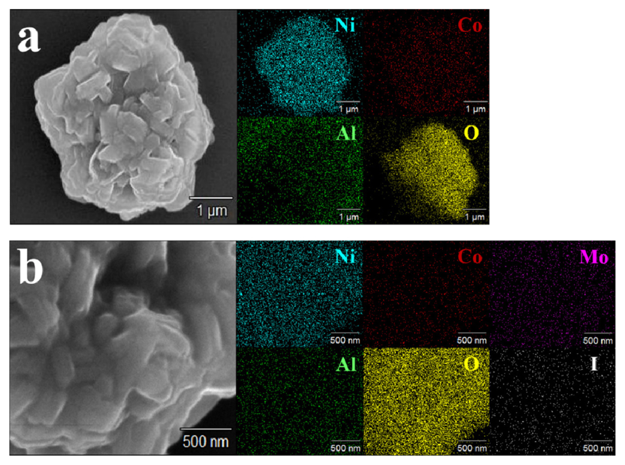
To reduce the side reactions at the cathode/sulfide electrolyte interface, the surface of NCA cathode was coated using Li2MoO4-LiI. To observe the change in cathode powder during coating, the surface morphology and crystal structure were analyzed. Fig. 2 shows the SEM image of the pristine and Li2MoO4-LiI coated cathode powders. As shown in Figure 2a, the surface of the pristine powder seemed to be already covered with a thin film, which consists of impurities such as Li2CO3 or LiOH formed while manufacturing [30,31]. The surface of the coated powder appeared to be covered with a thicker layer, which is expected to be a Li2MoO4-LiI coating (Figure 2b). Figure 3 presents the SEM and elemental mapping images of the pristine and coated powders. As shown in Figure 3b, not only Ni, Co, and Al, but also Mo and I were homogeneously distributed on the surface of the coated powder, which illustrates that the Li2MoO4-LiI coating layer was formed successfully on the surface of the cathode powder.
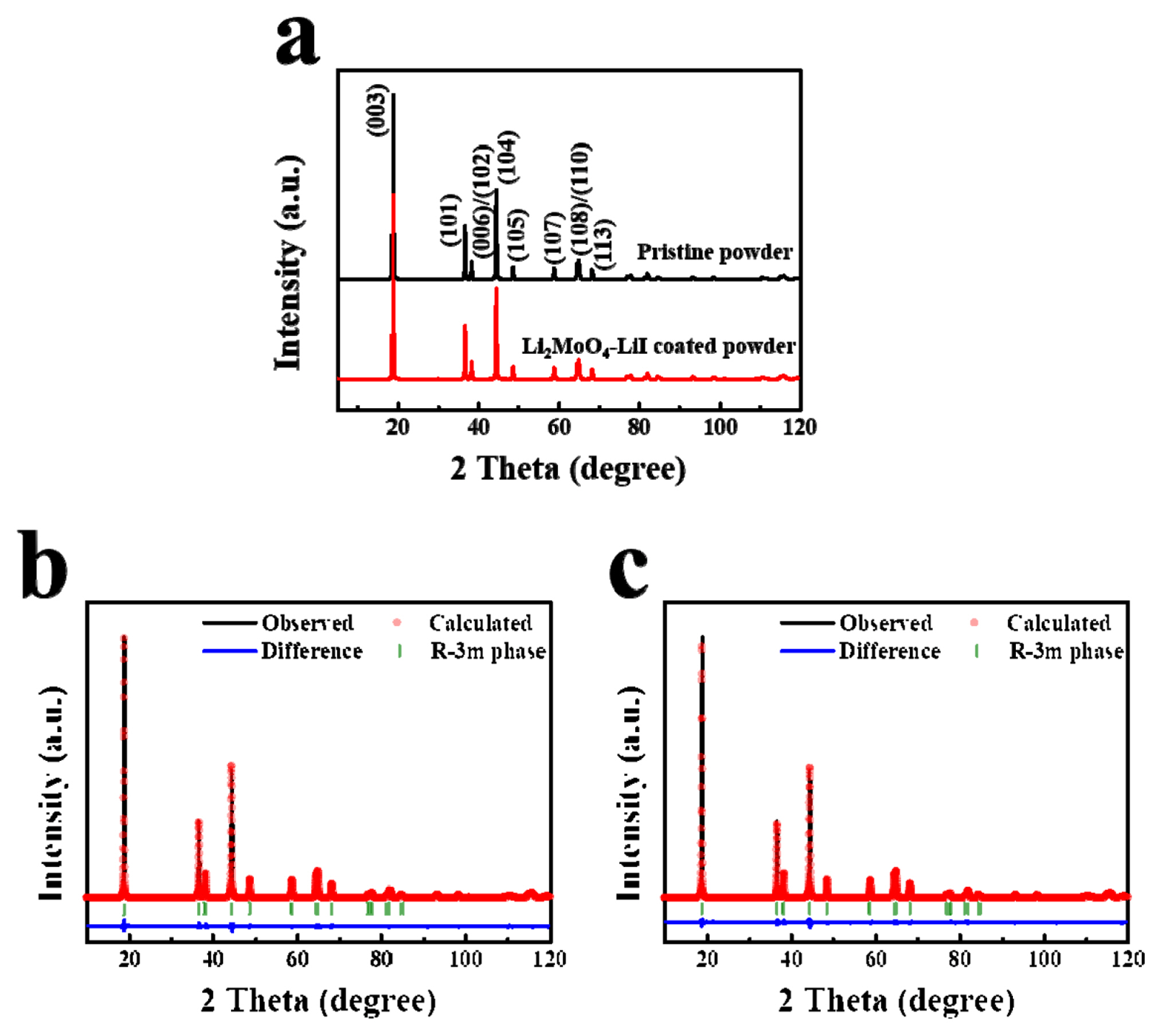
The crystal structures of the pristine and coated powders were observed by XRD. As shown in Figure 4a, the diffraction peaks of the pristine and Li2MoO4-LiI coated powders were almost similar, which indicates that the surface coating did not critically affect the crystal structure of the NCA powders. The diffraction peaks of the samples were in good agreement with the typical patterns of the α-NaFeO2 structure (space group R−3m). For a detailed examination, the XRD patterns were analyzed using Rietveld refinement. Fig. 4b and 4c show the observed and calculated XRD patterns of the pristine and coated powders, respectively, and Table 2 summarizes the crystal structural parameters of the powders. The calculated lattice parameters a and c and the unit cell volume (V) of the pristine powder were 2.8734 Å, 14.1977 Å, and 101.5192 Å3, respectively. The parameters of the coated powder were changed to 2.8729 Å (a), 14.1981 Å (c), and 101.4826 Å3. However, the difference between the parameters of the powders does not seem meaningful. The I(003)/I(104) values are related to the degree of cation mixing within the cathode materials [32]. Some Ni ions moved to Li sites (cation mixing), which reduced the rate capability because the Ni ions in the Li sites disturbed the lithiation and delithiation during cycling. The I(003)/I(104) values were slightly increased from 2.0109 (pristine) to 2.0139 after surface coating, which may exhibit a slight reduction in cation mixing after surface coating. However, the difference between the I(003)/I(104) values was almost negligible. Overall, the surface coating does not affect the crystal structure of the cathode powders significantly.
In order to identify the effect of the Li2MoO4-LiI coating, the electrochemical performance of the ASSCs containing coated NCA and the three types of sulfide electrolytes was observed. Regardless of the electrolyte used, the discharge capacity of the cells was increased by surface coating at all current densities, as shown in Fig. 5a. Fig. 5b–d compare the charge-discharge profiles of the pristine and coated cathodes at a current density of 8.5 mA·g−1 (the first cycle in Fig. 5a). The initial capacities of the cells containing coated NCA prepared using Argyro, LPS1, and LPS2 as electrolytes were ~ 205, ~ 157, and 144 mAh·g−1, respectively. Considering that the values of the uncoated cathodes were ~ 174, 100, and 95 mAh·g−1, it is clear that the Li2MoO4-LiI coating successfully enhanced the capacity of the ASSCs containing NCA. Moreover, the Coulombic efficiency of the initial cycles was also improved by the Li2MoO4-LiI surface coating. While the Coulombic efficiencies were ~ 66 (Argyro), ~ 49 (LPS1), and ~ 44% (LPS2) before coating, they increased to ~ 77 (Argyro), ~ 74 (LPS1), and ~ 62% (LPS2) by the coating. Table 3 compares the discharge capacity and Coulombic efficiency of the ASSCs containing pristine and coated cathodes in the initial cycle (current density of 8.5 mA·g−1).
The enhanced capacity and Coulombic efficiency of the surface coating are attributed to the protection of the coating layer. The Li2MoO4-LiI surface coating layer successfully suppressed the undesirable interfacial reactions between cathodes and electrolytes, which facilitated the movement of the Li ions during cycling. However, despite the protection of the surface coating, the cell containing LPS1 and LPS2 presented inferior capacity and Coulombic efficiency to the cell containing Argyro. This indicates that the high reactivity of LPS1 and LPS2 cannot be fully suppressed by the Li2MoO4-LiI surface coating layer. Therefore, in order to suppress the undesirable interfacial reaction in cathode/sulfide electrolytes, it is necessary to form a suitable surface coating layer on the cathode surface and use a suitable sulfide electrolyte which exhibits low reactivity with oxide cathodes. However, the protection of surface coating is more when using LPS1 and LPS2 than that when using Argyro. As shown in Table 3, if the degree of improvement by coating is defined as the ‘improvement rate’, the improvement rate of LPS1 and LPS2 is much higher than that of Argyro.
The interfacial properties between cathodes and solid electrolytes are dependent on the contact stability as well as the chemical reactivity of the electrolyte. The contact between the cathode and solid electrolyte is formed by mechanical pressing, so that the surface area of cathode does not physically connect to the solid electrolyte. Therefore, not only the undesirable interfacial reaction but also the contact instability at the cathode/electrolyte, is the main reason for deteriorating electrochemical performance of ASSCs. An approach to improve the contact stability is to reduce the particle size of the electrolyte. As the particle size decreases, the contact area between the cathode and electrolyte becomes wider, which facilitates the movement of Li ions and enhances the electrochemical properties of ASSCs [28,33,34]. In order to observe the effect of particle size, Argyro was pulverized using wet-ball milling and the electrochemical properties of the cells containing pulverized Argyro were analyzed. The average particle size of Argyro decreased from 15–20 μm to 3–4 μm through pulverization. However, the milling also decreased the ionic conductivity to ~ 1 mS·cm−1.
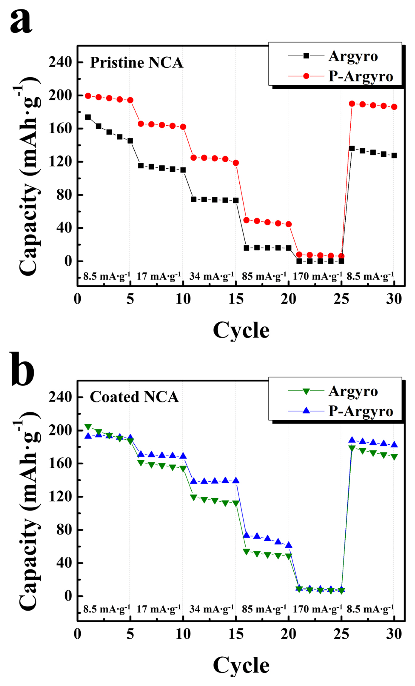
Nevertheless, the ASSCs containing pulverized Argyro (P-Argyro) presented superior electrochemical performance compared to those containing pristine Argyro. Fig. 6 compares the discharge capacities of the cells containing Argyro and P-Argyro as electrolytes at various current densities. As shown in Fig. 6a, the discharge capacity of the pristine NCA significantly increased by P-Argyro compared to that of Argyro. This indicates that the positive effect due to the improved contact between the cathode and electrolyte is much greater than the negative effect attributed to the reduced ionic conductivity. However, the effect of using pulverized Argyro on the performance of Li2MoO4-LiI coated NCA was relatively small. As shown in Fig. 6b, at low current densities (8.5 mA·g−1), the discharge capacities of the cell containing P-Argyro were similar to the cell containing the pristine Argyro. It is considered that the capacity of the surface-coated cathode can be sufficiently exhibited at low current density, even though the contact area between the cathode and the electrolyte is relatively insufficient. This is attributed to the easy movement of Li ions between them owing to the reduced interfacial reactions by surface coating. However, as the current density increased, the cell using P-Argyro exhibited a higher capacity than the cell using pristine Argyro, indicating that the improved contact significantly affects the high current densities. Moreover, it is also clear that the capacity and rate capability of the cells containing P-Argyro were enhanced by the introduction of Li2MoO4-LiI coating. The best performance of the cell was obtained by surface-coated NCA and pulverized Argyro, which is attributed to the synergistic effect of the suppression of interfacial reaction and improved contact stability.
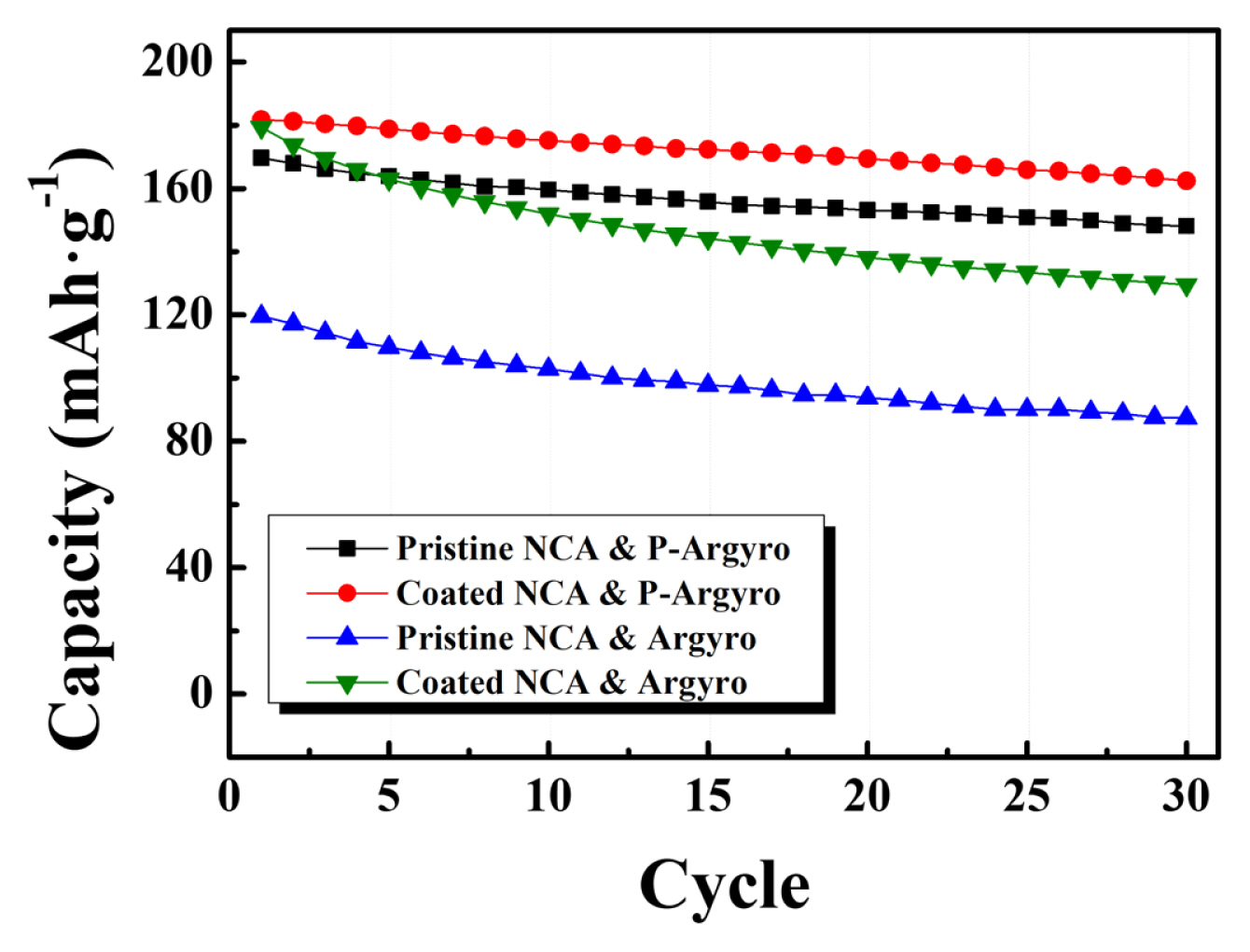
Fig. 7 shows the cyclic performance of the cells containing pristine and Li2MoO4-LiI coated NCA prepared using Argyro and P-Argyro as electrolytes. When Argyro was used as the electrolyte, the discharge capacity of the pristine NCA was ~ 119 mAh·g−1 at 17 mA·g−1. The discharge capacity of Li2MoO4-LiI coated NCA increased to ~ 179 mAh·g−1 due to the coating. However, the capacity fading did not improve by coating during cycling. This indicates that the capacity fading of cells is not mainly attributed to the undesirable interfacial reaction between the cathode and sulfide electrolyte. In contrast, the cyclic performance of the cell was significantly enhanced by the pulverized Argyro instead of pristine Argyro. The capacity retention during 30 cycles of the Li2MoO4-LiI coated NCA was only ~72% when pristine Argyro was used as the electrolyte. However, the capacity retention of the coated NCA enhanced to ~ 89% when pulverized Argyro was used. Moreover, the pristine NCA also exhibited good capacity retention of ~ 87%, although its capacity was slightly lower than that of the coated NCA owing to the interfacial reaction. Therefore, the rapid capacity fading of the cells using pristine Argyro is mainly associated to the unstable contact between the cathode and solid electrolyte. The effect of the surface coating on cyclic performance was not critical within 30 cycles. However, the possibility of reducing the capacity degradation in long cycles, owing to the suppression of interfacial reactions cannot be excluded.
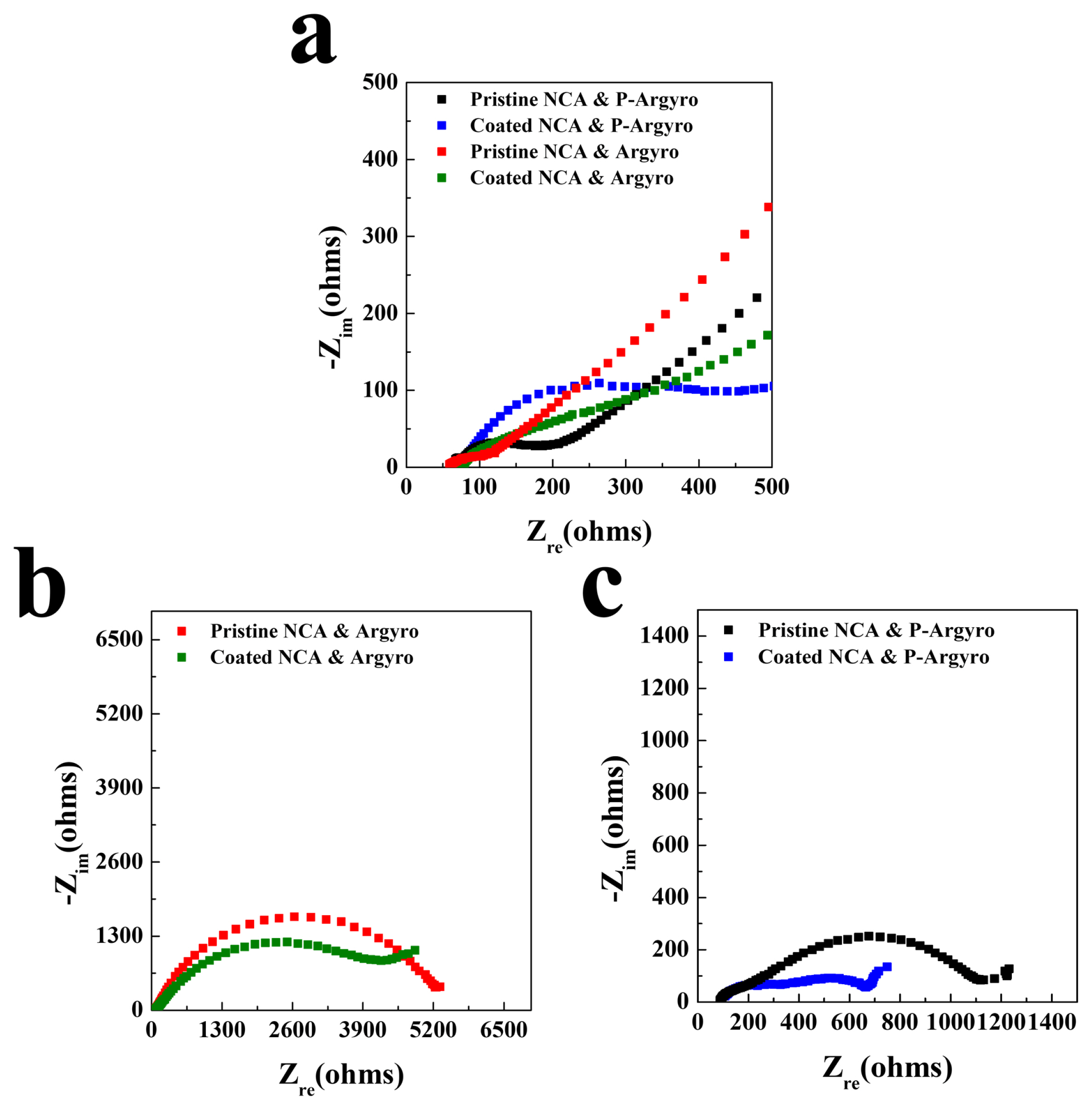
To observe the effect of surface coating and the use of pulverized electrolyte in detail, the impedance of ASSCs was measured. As shown in Figure 8, the Nyquist plots of the cells showed distorted semicircles because of the overlapping of several resistive components. However, the size of the semicircles represents the impedance value of the cells. As shown in Figure 8a, the semicircles of the cells using P-Argyro are smaller than those using pristine Argyro before the electrochemical test, which indicates that using pulverized electrolyte can reduce the impedance of the cells. It is interesting that the cells containing coated cathodes showed larger semicircles than the cells containing pristine cathodes. This means that the Li2MoO4-LiI coating layer acts as a resistive layer, increasing the impedance before the electrochemical test. However, as shown in Fig. 8b and 8c, after 5 cycles, the cells containing the coated cathode showed smaller semicircles than the cells containing the pristine cathode, indicating that the Li2MoO4-LiI layer can reduce the impedance during cycling. This lower impedance value attributed to the coating layer can explain the enhanced capacity and rate capability of the coated cathodes, as shown in Fig. 5. Moreover, the cells using P-Argyro have smaller impedance values compared to the cells using pristine Argyro, after cycling. Therefore, it is clear that the surface coating and pulverized solid electrolyte are effective approaches to reduce the impedance and enhance the electrochemical performance of ASSCs.
4. Conclusions
The electrochemical performance of the ASSCs was observed using three types of sulfide electrolytes. Despite using the same NCA cathode, the capacity of ASSCs was highly dependent on the sulfide electrolyte used in cells. The cell using Argyro exhibited superior electrochemical performance compared to the cells using LPS1 and LPS2, which is attributed to the relatively lower reactivity of Argyro with the cathode than that of other sulfide electrolytes. However, the electrochemical performance of ASSCs is much inferior to that of conventional cells owing to the undesirable interfacial reactions and contact instability at the cathode/sulfide electrolyte layer. The capacity and Coulombic efficiency of the ASSCs were significantly enhanced by the introduction of Li2MoO4-LiI coated cathode. This indicates that the coating layer successfully suppressed the undesirable interfacial reaction between the cathode and sulfide electrolytes. The cells using Argyro still presented higher capacity and Coulombic efficiency than the cells using other electrolytes, indicating that the electrochemical performance of ASSCs is significantly influenced by the use of sulfide electrolytes, despite the application of surface coating to the cathode. The pulverization of Argyro also enhanced the electrochemical performance of ASSCs by improving the contact instability between the cathode and electrolyte. Moreover, the cyclic performance distinctly improved by pulverized Argyro because the cyclic performance of ASSCs is more dependent on the contact instability than the interfacial reaction at the cathode/electrolyte. The impedance of ASSCs reduced by the use of pulverized Argyro and the Li2MoO4-LiI coating was introduced, which may contribute to the higher capacity and better rate capability of these cells.