Enhanced Electrochemical Properties of All-Solid-State Batteries Using a Surface-Modified LiNi0.6Co0.2Mn0.2O2 Cathode
Article information
Abstract
Undesirable interfacial reactions between the cathode and sulfide electrolyte deteriorate the electrochemical performance of all-solid-state cells based on sulfides, presenting a major challenge. Surface modification of cathodes using stable materials has been used as a method for reducing interfacial reactions. In this work, a precursor-based surface modification method using Zr and Mo was applied to a LiNi0.6Co0.2Mn0.2O2 cathode to enhance the interfacial stability between the cathode and sulfide electrolyte. The source ions (Zr and Mo) coated on the precursor-surface diffused into the structure during the heating process, and influenced the structural parameters. This indicated that the coating ions acted as dopants. They also formed a homogenous coating layer, which are expected to be layers of Li-Zr-O or Li-Mo-O, on the surface of the cathode. The composite electrodes containing the surface-modified LiNi0.6Co0.2Mn0.2O2 powders exhibited enhanced electrochemical properties. The impedance value of the cells and the formation of undesirable reaction products on the electrodes were also decreased due to surface modification. These results indicate that the precursor-based surface modification using Zr and Mo is an effective method for suppressing side reactions at the cathode/sulfide electrolyte interface.
1. Introduction
Over the past several decades, the use of lithium ion batteries (LIBs) has grown tremendously, triggering the revolutionary development of personal electronics [1–7]. Recently, LIBs have been applied to energy storage systems (ESS) and electric vehicles, and consequently are in the midst of a new growth phase. However, safety issues caused by the use of flammable liquid electrolytes are serious problems that hinder the growth of LIB industry. All-solid-state lithium batteries (ASSLBs) that use nonflammable inorganic solids as electrolytes are an obvious solution to this problem [8–14]. In addition, they are beneficial in the operable temperature range as the inorganic solid electrolytes are stable at both high (100 – 200°C) and low (−30 – 50°C) temperatures, whereas an organic liquid electrolyte would not be sustainable at these temperatures [15–17]. However, the commercialization of ASSLBs faces several challenges despite their potential advantages. The lower ionic conductivities of solid electrolytes than those of liquid electrolytes have been a major issue in the ASSLBs. In recent years, however, significant progress has been made in the development of inorganic solid electrolytes with high ionic conductivity [18–21]. Especially, some sulfide electrolytes exhibited superior ionic conductivity than that of commercial organic liquid electrolytes [22–23]. However, the issue of high interfacial resistance between the electrodes (cathode and anode) and solid electrolytes has not yet been resolved [15–17].
The sulfide solid electrolytes have attracted much attention owing to their high ionic conductivity and good ductility [24–28]. However, they easily react with the oxide cathodes and form an interfacial layer, which prevents the movement of electrons and lithium ions during cycling [10–14]. Surface modification of the cathode using lithium ionic conductors has been suggested as an effective method to reduce the interfacial resistance between the cathode and sulfide electrolyte. Several materials such as LiNbO3 [29–30], Li4Ti5O12 [31], Li3xLa2/3−xTiO3 [32], and Li2O–SiO2 [33] have been used for the surface modification of the cathode in ASSLBs. In most cases, the surface modification was performed using a solution method on the as-synthesized cathode, which is termed the post-coating route. Although this method protects the surface to a certain extent, it is unlikely to result in a doping effect that would be beneficial for the stabilization of the cathode. Moreover, the coating layer prepared using the post-coating route generally does not cover the surface of the cathode completely [12,24].
In this study, we proposed a precursor-based surface modification process. In this modification process, the coating sources were first coated on the surface of the precursors (Ni0.6Co0.2Mn0.2(OH)2). Zr and Mo were selected as the coating source as they have been used as stable coating materials and they form Li-M-O oxides (M=Zr or Mo) with good ionic conductivity [34–35]. The coated precursors were then calcined with a lithium source to form the cathode (LiNi0.6Co0.2Mn0.2O2) and coating layer (Li-Zr-O and Li-Mo-O). During this process, cation migration (or doping) from the coating sources may occur, which enhances the binding between the surface layer and parent cathode [36, 37]. In addition, the surface layer of the cathode is also more homogeneous than the post-coating route. This surface-modified cathode is expected to reduce the interfacial reaction with the sulfide electrolyte, which results in an enhanced capacity and rate capability of the all-solidstate cells. In this work, the effect of precursor-based surface modification was carefully observed using X-ray diffraction, field-emission scanning electron microscopy, X-ray photoelectron spectroscopy, and electrochemical analysis.
2. Experimental
The cathode precursor powder (Ni0.6Co0.2Mn0.2(OH)2 powder) was supplied by the company Eco & Dream, Korea. To prepare a coating solution, zirconium (IV) oxynitrate hydrate (N2O7Zr·xH2O, Aldrich) and phosphomolybdic acid (HPMO) solution (H3[P(Mo3O10)4], 20 wt. % in ethanol) were separately dissolved in anhydrous ethanol (99.9%, Aldrich) at 80°C. The amount of coating material was adjusted to 1 wt.% based on the transition metals present in the cathode precursor. After the coating materials were completely dissolved in the solvent, the cathode precursor powder was added and stirred at 80°C until the solvent evaporated completely. The dried materials were mixed with LiOH·H2O at a molar ratio of 1 : 1.08, and the mixtures were heated at 500°C for 5 h and at 800°C (heating rate = 2°C/min) for 10 h under an oxygen atmosphere to obtain precursor-based surface-modified LiNi0.6Co0.2Mn0.2O2 powders. Using the same materials and ratios, LiNi0.6Co0.2Mn0.2O2 was prepared without surface modification.
For sample characterization, X-ray diffraction (XRD) patterns of the pristine and surface-modified powders were obtained using an X-ray diffractometer (Bruker D8) over a 2θ range of 5 – 120° with monochromatized Cu Kα radiation (λ = 1.5406 Å). The Highscore software was used to refine the lattice parameters for the Rietveld analysis. The surface morphology of the samples was analyzed using field-emission scanning electron microscopy (FE-SEM, Nova Nano 200). Energy dispersive X-ray spectroscopy (EDS) mapping was carried out to distinguish the elements present in the powder. X-ray photoelectron spectroscopy (XPS) was also used to clearly determine the presence of elements on the powder surface.
All-solid-state cells were assembled using a sulfide-based electrolyte (LPS-LiCl, JEONG KWAN Co. LTD). The cathode composite was prepared by hand mixing using an agate mortar in a glovebox filled with argon to prevent the deterioration of the sulfide solid electrolyte. The ratio of the cathode, the sulfide solid electrolyte, and the conductive material (Super P) was adjusted to 70:30:2 for proper mixed-conductivity of the cathode composite.
To make the separator layer, 0.2 g of the sulfide electrolyte was compressed under 30 MPa pressure in a Φ16 mold. Subsequently, 0.02 g of the prepared cathode composite was dispersed on the separator, and a carbon nanotube paper (Hanwha Chemical) was placed above. Li-In powder was used to increase the stability of the Li metal powder. The powder was used to the anode electrode, 0.05 g on the opposite side. Each compression was performed under a pressure of 30 MPa. The formed pellets were assembled into 2032 coin-type cells, which were galvanostatic cycled (WonATech system) using a 3.88–1.88 V potential window at various charge-discharge rates. Electrochemical impedance spectroscopy (EIS) was performed using VersaSTAT3 (Princeton). The analysis was carried out in the frequency range of 0.1 MHz to 0.01 Hz by applying a 10 mV signal amplitude.
XPS (Thermo Scientific K-Alpha plus) was employed to analyze the interfacial reaction of the composite electrodes. The composite electrodes before and after cycling were separated from the cells, and vacuum transfer was used to minimize the contamination of the electrodes before the analysis.
3. Results and Discussion
The surface morphology of the pristine and surface-modified samples was observed using SEM. For convenience, the pristine sample, surface-modified sample using Zr, and surface-modified sample using Mo were termed as NCM622, NCM-Zr, and NCM-Mo, respectively. As shown in Fig. 1, all the samples present a similar circular shape composed of nanograins and a clean surface without any special particles attached. It is noted that, the change in the morphology due to surface modification could not be observed clearly using SEM. However, the possibility that the NCM-Zr and NCM-Mo samples were covered with a thin film-like coating layer could not be excluded. In general, the coating layer formed using the post-coating route is easily distinguished in SEM images [12,24]. However, a relatively higher temperature and a longer heat-treatment process is employed in the precursor-based surface modification process as compared to that in the post-coating route, which may lead to a thin and homogeneous coating layer that is not easily distinguishable from the parent cathodes. Fig. 2 shows the SEM and elemental mapping images of the surface-modified samples. Zr and Mo were distributed homogeneously on the surface of the NCM-Zr and NCM-Mo, respectively. It can be inferred that the coating layer containing Zr and Mo was formed due to surface modification. However, it is also possible that Zr and Mo were completely diffused and acted only as dopants rather than components of the coating layer. The amounts of Zr and Mo in the samples analyzed by ICP-MAS were 0.22 wt.% (Zr in NCM-Zr) and 0.35 wt. % (Mo in NCM-Mo), respectively.
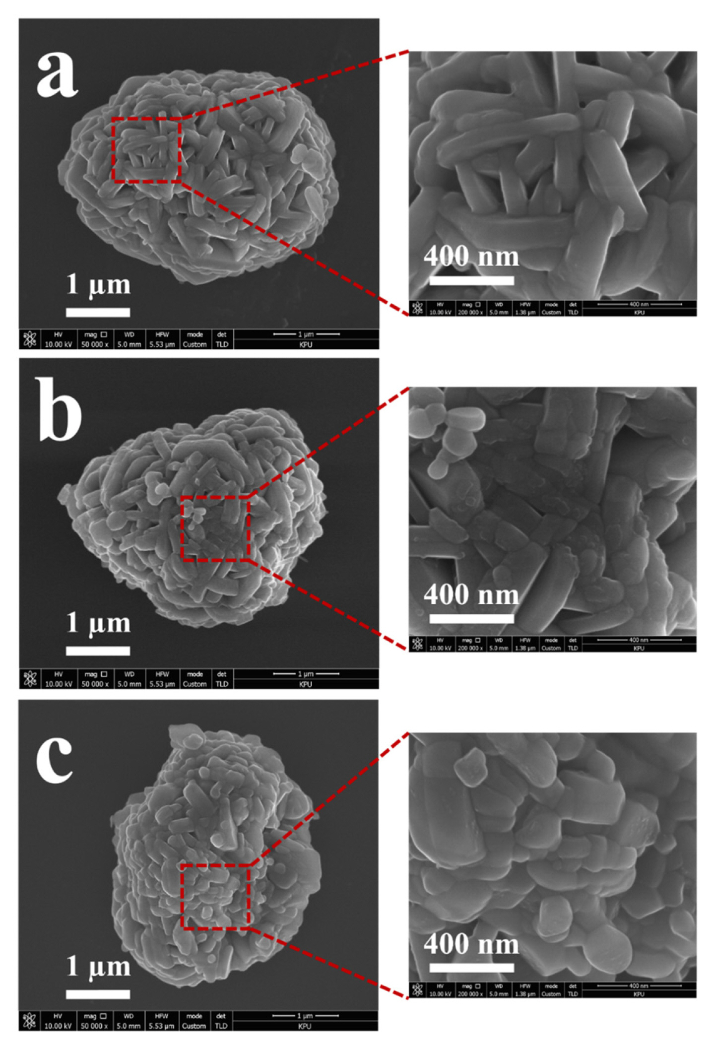
SEM images of pristine and surface-modified LiNi0.6Co0.2Mn0.2O2 powders. (a) NCM622, (b) NCM-Zr, and (c) NCM-Mo.

SEM and elemental mapping images of surface-modified
The surface of the sample powders was characterized using the XPS depth profiles obtained from the surface to a certain depth using an ion-gun etching system to clearly confirm the existence of the coating layer. As shown in Fig. 3a, the NCM-Zr sample exhibits two distinct peaks, corresponding to Zr 3d3/2 (~184.3 eV) and 3d5/2 (~181.9 eV) in the XPS spectra, while the pristine powder does not exhibit detectable peaks. Interestingly, the intensity of the two peaks decreased as the etching time increased. This shows that the amount of Zr gradually decreases with increasing depth of the NCM-Zr sample, indicating the existence of a surface coating layer that contains a high concentration of Zr ions; however, some portion of the Zr ions diffuse into the structure. As shown in Fig. 3b, the intensity of the two peaks corresponding to Mo 3d3/2 and 3d5/2 also decreased as the etching time increased, confirming the formation of a surface coating layer, which contains Mo, during the surface modification process.
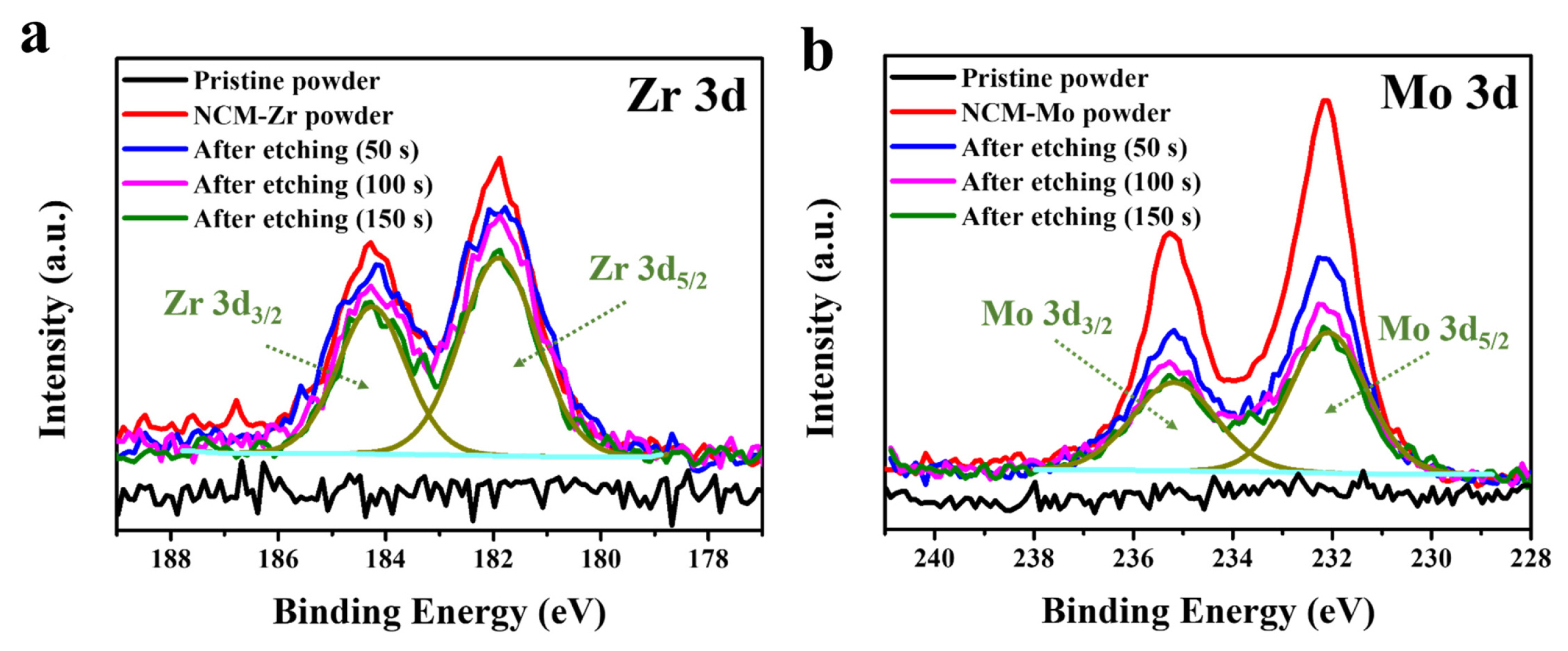
XPS spectra of the pristine and surface-modified powders before and after etching (a) Zr 3d and (b) Mo 3d.
The precursor-based surface modification process is expected to result in a cationic migration of the coating ions as well as the formation of a coating layer. In order to characterize the effect of this, the crystal structure of the samples was observed using XRD. As shown in Fig. 4a, the pristine and surfacemodified samples present similar diffraction peaks, indicating that the structure of the samples is not critically affected by the surface modification. They can be well-indexed by the α-NaFeO2 structure (space group R−3m). As shown in Fig. 4b, the position of the diffraction peaks does not change significantly, except for a slight shift in several peaks. However, it is noteworthy that the I(003)/I(104) values increased due to the surface modification. The I(003)/I(104) value is associated with the degree of cation mixing within the cathode material [36]. A portion of the Li sites in the NCM622 are occupied by Ni ions (cation mixing), which negatively affect the rate capability of the cathode as the presence of Ni ions in the Li sites disturbs the movement of Li ions during charging/discharging. The I(003)/I(104) value of NCM622 was 1.866, and that of NCM-Zr and NCM-Mo was 1.988 and 2.061, respectively. The increased I(003)/I(104) value due to surface modification indicated that the Zr and Mo ions in the cathode reduce cation mixing. Thereby, we inferred that the surface-modified samples were favorable for increasing the rate capability.

XRD patterns of pristine and surface-modified powders. (a) XRD patterns of powder, and (b) magnified near the (003), (104), (006)/(012), and (108)/(110) peaks.
Fig. 5 shows the observed and calculated XRD patterns using Rietveld refinement to analyze the effect on the structure due to surface modification in detail. The calculated lattice parameters a and c and the unit cell volume (V) of NCM622 were 2.8644 Å, 14.209 Å, and 100.96 Å3, respectively; However, the values for the NCM-Zr sample decreased to 2.8624 Å (a), 14.205 Å (c), and 100.79 Å3, respectively. Moreover, NCM-Mo showed much lower values of a (2.8610 Å), c (14.202 Å), and the unit cell volume (100.67 Å3). This result may be attributed to the doping effect of Zr and Mo ions during surface modification. Zr and Mo can diffuse into the cathode and incorporate into the NCM622 structure due to the high heating temperature and long heating duration of the precursor-based surface modification process. The ionic radii of Zr4+ (0.745 Å) are larger than those of the transition-metal ions such as Ni2+ (0.69 Å), Co3+ (0.545 Å), and Mn4+ (0.53 Å) present in LiNi0.6Co0.2Mn0.2O2; thus, the substitution of transition-metal ions by Zr4+ does not reduce the lattice parameter of the cathode. Considering that the ionic radius of Li+ (0.76 Å), the Zr4+ ions may migrate into the Li sites of the cathode structure. A previous study has also reported a reduction in the lattice parameter due to Zr doping and has assumed that the Zr4+ ions occupied the Li sites [38]. It is also reasonable to assume that the Mo5+ (0.61 Å) or Mo6+ (0.59 Å) ions moved to the Li sites during the surface modification process as the lattice parameter was largely reduced due to the doping effect of Mo. However, the possibility that some of the Ni2+ ions are substituted by Mo5+ (or Mo6+) ions cannot be excluded. Table 1 summarizes the crystal structural parameters of NCM622, NCM-Zr, and NCM-Mo. The diffraction peak related to the surface coating layer (expected for Li2ZrO3 or Li2MoO4) was not detected in the XRD analysis, which may be due to their small amount. Therefore, the exact composition of the coating layer could not be confirmed in this study. However, as shown in Fig. 3, high concentration of Zr or Mo may result in a reaction with Li and O, which is expected to form Li-Zr-O and Li-Mo-O oxides as coating layers or concentration-gradients in the cathodes.
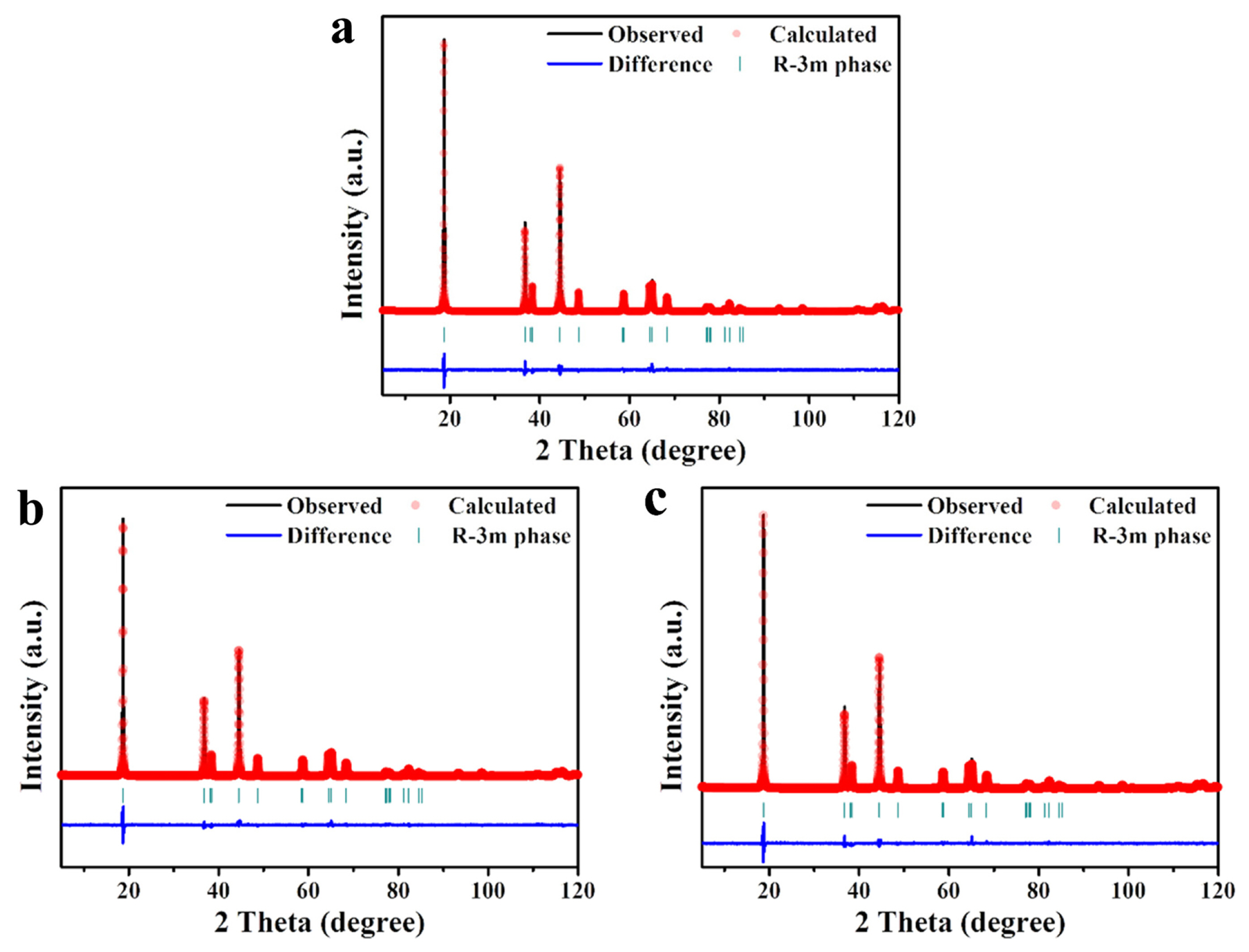
XRD patterns of pristine and surface-modified powders. Rietveld refinements of (a) NCM622, (b) NCM-Zr, and (c) NCM-Mo.
The crystal structural parameters of NCM622, NCM-Zr, and NCM-Mo.
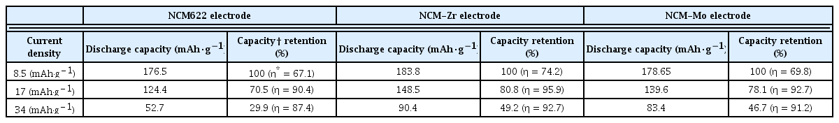
The electrochemical performance of the composite electrodes containing NCM622, NCM-Zr, and NCM-Mo powders were measured using the sulfide solid electrolyte. Fig. 6a shows the change in discharge capacities at various current densities (8.5, 17, 25.5, and 34 mA·g−1). The voltage range was set to 3.88~1.88 V, considering the voltage drop at the anode (Li-In). At a current density of 8.5 mA·g−1, the discharge capacities of the electrodes were 176.5 (NCM622), 183.8 (NCM-Zr), and 178.7 (NCM-Mo) mAh·g−1. Although the surface-modified samples presented a slightly higher capacity, the difference in the capacities was not prominent. However, as the current density increased, the capacity difference between the pristine and surface-modified electrodes significantly increased. At current densities of 17 and 34 mA·g−1, the discharge capacity of the NCM622 sample was 124.4 and 52.7 mAh·g−1, respectively. However, at the same current densities, the discharge capacity of the NCM-Zr increased significantly to 148.5 and 90.4 mAh·g−1, respectively. The NCM-Mo also exhibited higher capacities of 139.6 (at 17 mA·g−1) and 83.4 mAh·g−1 (at 34 mA·g−1) than those of the NCM622. The retained capacity of NCM622 at 34 mA·g−1 as compared to that at 8.5 mA·g−1 was just 29.9%. In contrast, those of NCM-Zr and NCM-Mo were improved to 49.2 and 46.7%, respectively. This indicated that the surface modification effectively enhanced the rate capability of the cells.
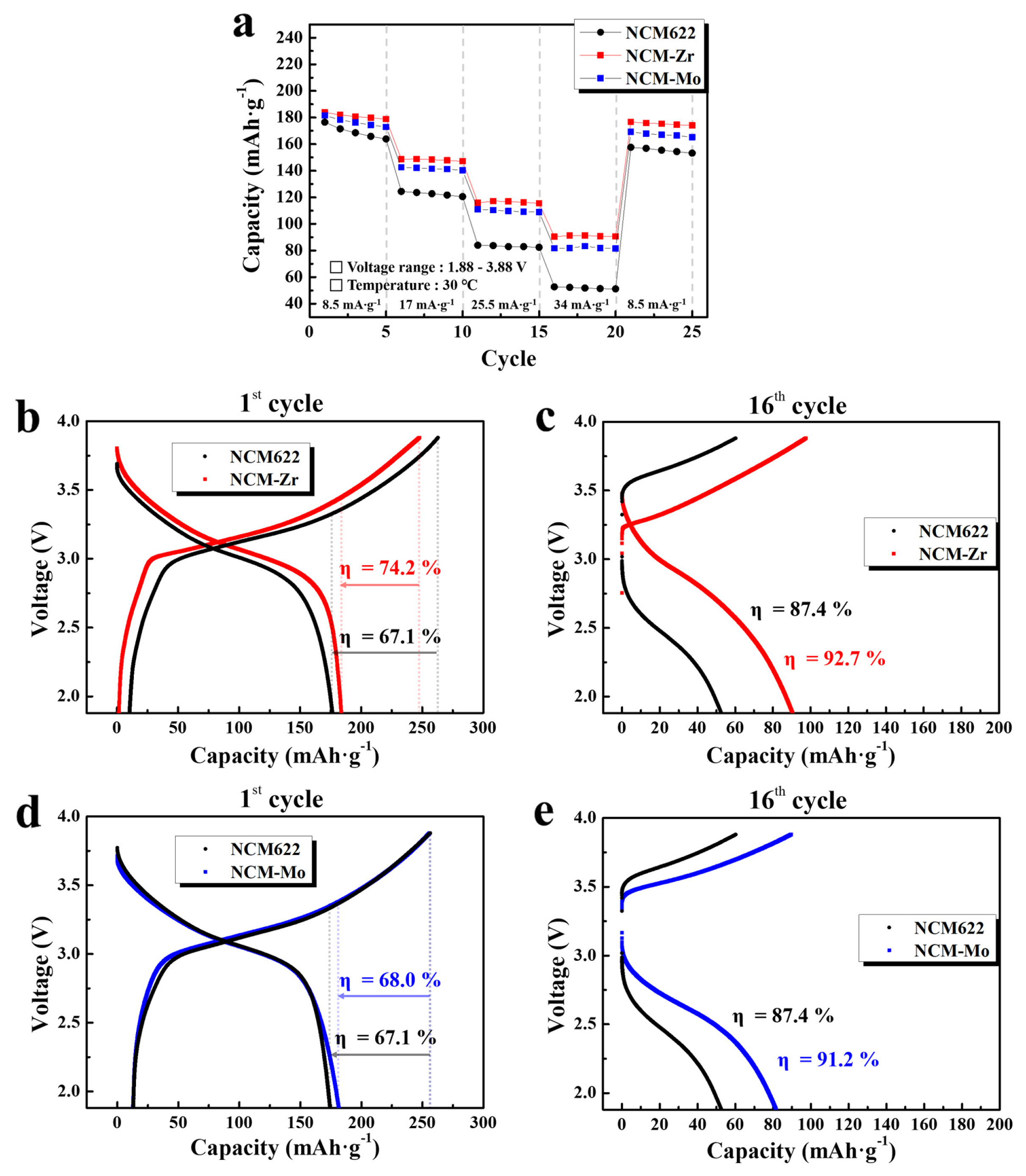
(a) Discharge capacities of pristine and surface modified electrodes at current densities of 8.5, 17, 25.5, and 34 mA·g−1. Charge-discharge profiles of the NCM622 and NCM-Zr at (b) 8.5 and (c) 34 mA·g−1, and those of NCM622 and NCM-Mo at (d) 8.5 and (e) 34 mA·g−1.
The significant drop in capacity of the all-solid-state cells at high current densities was largely dependent on the unstable interface between the cathode and sulfide electrolyte. The undesirable interfacial layer formed due to the side reactions at the cathode/sulfide electrolyte interface increased the resistance of the all-solid-state cell, which significantly decreased the capacity at high current densities. The enhanced rate capability of the electrodes containing NCM-Zr and Mo indicated that the precursor-based surface modification successfully reduced the side reactions between the cathode and sulfide electrolyte. Fig. 6b–6e show the charge-discharge profiles of the composite electrodes. As seen in Fig. 6b and 6d, the voltage profiles at 8.5 mA·g−1 (initial cycle in Fig. 6a) do not show the effect of the surface modification clearly. However, at 34 mA·g−1 (16th cycle in Fig. 6a), the capacity and columbic efficiency of the cells are significantly improved by the surface modification, as shown in Fig. 6c and 6e. The discharge capacity, capacity retention, and columbic efficiency (η) of the electrodes are summarized in Table 2.
Electrochemical properties of pristine and surface-modified electrodes at different current densities.
The effect of the surface modification on the cyclic performance of the electrodes has also been characterized, as shown in Fig. 7. At a current density of 17 mA·g−1, the initial discharge capacity of NCM622 was ~ 136 mAh·g−1, which gradually decreased to ~ 102 mAh·g−1 during 30 cycles. The capacity retention after 30 cycles was approximately 75%. In contrast, NCM-Zr and Mo presented much higher capacities of approximately ~157 and ~159 mAh·g−1 after 30 cycles, respectively; furthermore, at the same current density, the capacity retention after 30 cycles was significantly improved to ~89% (NCM-Zr) and 81% (NCM-Mo). It was thought that this enhanced electrochemical performance, such as rate capability and cycle life, is attributed to the synergistic effect of the coating and doping of Zr and Mo. Side reactions at the cathode/sulfide electrolyte interface were suppressed by the coating layer on the surface of the NCM622. Furthermore, the doping effect derived from the diffusion of Zr and Mo also contributed to the reduction of cation mixing and stabilization of the structure.

Cyclic performance of pristine and surface-modified electrodes at a current density of 17 mA·g−1.
The impedance of the cells containing the samples was measured to observe the effect of the surface modification on the interfacial resistance. As shown in Fig. 8, the Nyquist plots of the cells consist of overlapped semicircles that are associated with several resistance components, showing an unstable interface. The size of the semicircle is related to the impedance value of the cells. As shown in Fig. 8a, the size of the semicircles of the cells before the test were increased due to the surface modification using Zr and Mo. This is attributed to the surface coating layer that acts as a new resistance component, which results in an increased impedance value of the cells before the tests. In contrast, the size of the semicircles of the cells after five cycles surprisingly decreased due to the surface modification. In particular, the impedance value of the cells after the surface modification using Zr is largely reduced compared to that after the surface modification using Mo, as shown in Fig. 8b. This may indicate that the Li-Zr-O layer is a more effective coating material for suppressing undesirable cathode/sulfide electrolyte interfacial reactions than the Li-Mo-O layer. This is well supported by the superior rate capability and stable cyclic performance of the NCM-Zr shown in Fig. 6 and 7.
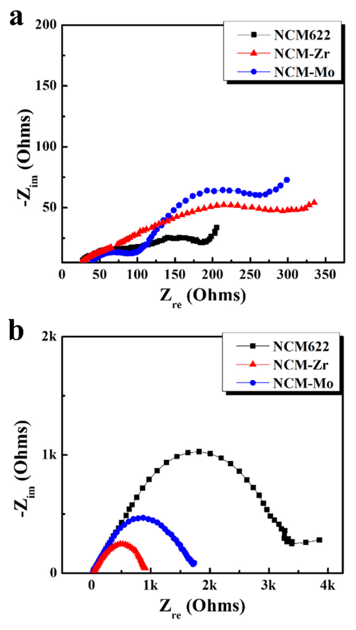
Nyquist plots of pristine and surface-modified electrodes in all-solid-state cells (a) before cycles and (b) after five cycles in a charged state.
The undesirable side reactions at the cathode/sulfide electrolyte interface were also characterized using the XPS analysis. The composite electrodes containing NCM622, NCM-Zr, and NCM-Mo were collected after 20 cycles, and their XPS spectra were recorded. As shown in Fig. 9a, the XPS spectrum of the NCM622 electrode before the test was composed of two main peaks (marked in orange). They are associated with the S 2p1/2 (~162.9 eV) and 2p3/2 (~161.7 eV) components of the non-bridging sulfur (S−) in the sulfide electrolyte [39]. The small peaks (marked in red) may be associated to the P-[S]n-P type bond [40]. They may also indicate the formation of reaction products from the side reactions such as the oxidation of sulfides. As shown in Fig. 9b–9d, the XPS spectra of the composite electrodes were significantly changed after the cycles. The intensity of the main peaks (marked in orange) is considerably decreased. In contrast, the intensity of the small peaks (marked in red and blue) was largely increased, which is attributed to the side reactions between the cathode and sulfide electrolyte. However, it can be clearly observed that the XPS spectra of the NCM-Zr (Fig. 9c) and NCM-Mo (Fig. 9d) exhibited relatively smaller peaks (marked in red and blue) as compared to those of the NCM622 (Fig. 9b). This result shows that interfacial side reactions were suppressed due to the surface modification using Zr and Mo. The surface coating layer reduced undesirable reactions between the cathode and sulfide electrolyte, and the enhanced stability by doping also contributed to the reduction of the reactivity of the cathode. This synergic effect may have enhanced the interfacial stability, which resulted in the improved rate capability and cyclic performance of the cells containing the surface-modified samples.

S 2p XPS spectra of the pristine electrolyte and composite electrodes of the all-solid-state cells (a) NCM622 before test, and after 20 cycles for (b) NCM622, (c) NCM-Zr, and (d) NCM-Mo electrodes.
4. Conclusions
To reduce undesirable side reactions between the cathode and sulfide electrolyte, the surface of LiNi0.6Co0.2Mn0.2O2 cathode was modified using either Zr or Mo. The coating process was initiated using a precursor to easily obtain a homogeneous coating of Li-M-O oxides (M=Zr or Mo). The precursor-based surface modification process influenced the structural parameters, indicating that the coating ions acted as dopants and formed a surface coating layer. The doped Zr and Mo reduced cation mixing, which may have enhanced the rate capability of the surface-modified electrodes. The surfacemodified electrodes using Zr and Mo exhibited an increased capacity, improved rate capability, and a stabilized cyclic performance as compared with those of the pristine electrode. The impedance value (after cycling) of the cells was also reduced due to the surface modification, confirming that the surface modification successfully reduced the interfacial resistance between the cathode and sulfide electrolyte. In particular, the surface modification using Zr was more effective than that using Mo to enhance the electrochemical performance and reduce the impedance value. Considering the XPS analysis results, the reaction products formed from undesirable side reactions during cycling were also reduced due to the surface modification. This indicated that the surface coating layer, which are expected to be Li-Zr-O or Li-Mo-O oxides, successfully suppressed the side reaction between the cathode and the sulfide electrolyte. The doping effect may have contributed to the structural stability of the cathode against the reactive sulfides. The synergistic effect of coating and doping was more effective than the single effect of coating or doping.
Acknowledgment
This work was supported by Kyonggi University Research Grant 2018.