1. Introduction
Excessive use of fossil fuels is without a doubt the main cause of current climate change and ever-increasing air pollution. There is an urgent need today to reduce carbon dioxide emissions in order to tackle upcoming environmental crisis. High energy density rechargeable batteries have drawn large attention as key devices for large-scale energy storage systems and electric transportation [1,2].
Recently, lithium-sulfur (Li-S) batteries have been highlighted as one of highly efficient and innovative battery systems due to the attractive features of sulfur: environmentally friendliness, low cost and high abundance in nature, and high theoretical capacity [3]. Significant efforts have been made to develop high performance and sustainable Li-S batteries in the past two decades [4–6]. Despite remarkable improvements, mass commercialization has been hampered by their low performance (e.g., practical energy density, cycle life, and sulfur utilization) and safety issues [4–6]. The insufficient performance of Li-S batteries is closely associated with the dissolution and diffusion of polysulfides [7].
Diverse strategies have been proposed to block the migration of polysulfides, including a carbon-sulfur composite, a porous carbon interlayer, and a modified separator with a protective coating [8–13]. These approaches have been shown to be highly effective for improving cycling stability and sulfur utilization. Substantially enhanced performance was obtained mostly with low sulfur loading (less than 2 mg/cm2) [14,15]. As a results the merit of sulfur and its high theoretical capacity are overshadowed, which makes the realization of competitive Li-S batteries impossible when compared to present lithium-ion batteries [15]. To address this issue, efforts toward increasing sulfur loading in the Li-S cells have focused on fabricating highly porous carbons such as graphene foam, free-standing carbon film and carbon nanotubes [16–21]. These carbon materials were found to be highly beneficial for making high-loading sulfur cathodes with high performance [19–22]. However, most of materials reported in the literature have been obtained through complex and expensive synthesis methods, which make their practical application difficult. Previously, we found that Li2S particles electrically isolated from the carbon cathode can be converted to elemental sulfur via the electrochemical reaction of medium order polysulfides that are generated by the chemical reactions between solid Li2S and polysulfides [23]. Based on this finding, we expected that additional active materials can be supplied to the cathode during charge process by including Li2S particles between a conventional sulfur cathode and a lithium metal anode. To achieve a high areal capacity, we suggest a new design of Li-S cell, composed of a sulfur cathode, lithium anode, and Li2S-impregnated glass fiber separator fabricated via a simple solution-based method.
2. Experimental
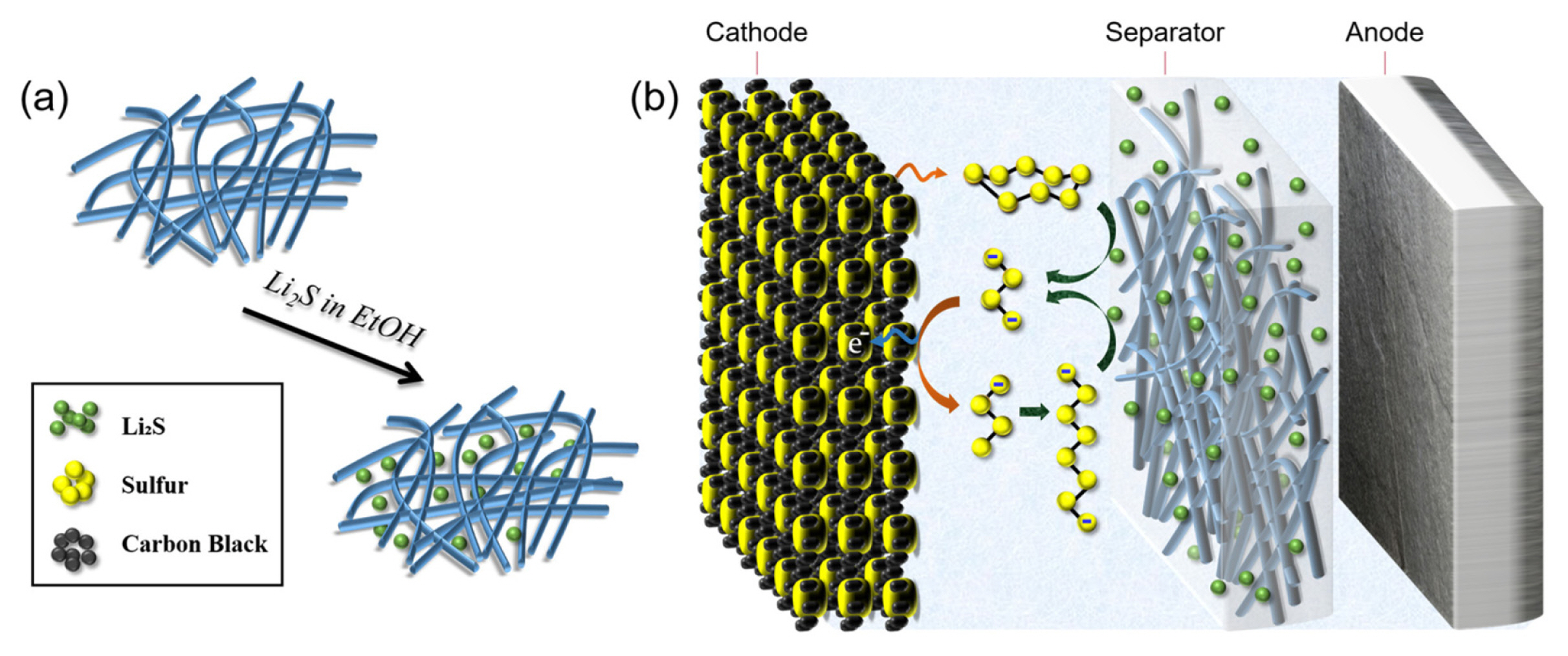
Li2S particles were incorporated into a glass fiber separator (Advantec, GC-50) by a solution-based infiltration method (Fig. 1a). Commercial Li2S powders (Aldrich) were dissolved in anhydrous ethanol (Aldrich) and stirred for 6 h to obtain a 0.80 M Li2S solution. The separator was submerged in a sealed vessel containing the Li2S solution for 5 h to ensure that Li2S penetrates deep into the separator. The obtained separator was dried at room temperature and then left at 40°C under vacuum for a day to completely evaporate ethanol. All the fabrication processes involving Li2S were performed in an argonfilled gloveboxif to avoid harmful reactions of Li2S with moisture and oxygen. The loading level of Li2S in the separator was ~2.3 mg/cm2. The surface morphologies of the pristine separator and the Li2S-embedded separator were analyzed by scanning electron microscopy (FIB-SEM, Helios Nanolab 600i, FEI). The distribution and crystallinity of Li2S were investigated by energy-dispersive X-ray spectroscopy (EDS) and X-ray diffraction spectroscopy (XRD), respectively.
The sulfur electrode consists of sulfur powder (Miwon chemicals, Korea), a conducting agent (Ketjenblack, International Co.) and a polyethylene oxide (Alfa Aesar) binder with a 6:2:2 weight ratio. It was fabricated by a slurry-casting method as described in our previous work [24]. On average, the sulfur loading on the cathode was ~2.0 mg/cm2.
Coin cells containing the Li2S-impergnated separator was assembled using 1.0 M LiN(CF3SO2)2 solution in dimethoxyethane (DME) : diglyme (DG) : 1,3-dioxolane (DOL) (6:2:2 in volume) with 0.3 M LiNO3 as an electrolyte. The sulfur electrode was used as a cathode and pure lithium metal as an anode. For comparison, a control cell was prepared following the same procedures, except for using a pristine glass fiber separator without Li2S. The Li-S cells with the Li2S-impregnated separator were charged to 4.0 V at 0.05 C in the first cycle after cell assembly. Subsequently, the Li-S cells were discharged and charged in the potential range between 1.8 V and 2.7 V at 0.05 C (vs. Li/Li+) for the initial two cycles. Thereafter, cycling stability and rate capability were tested with cut-off voltages of 1.8 V and 2.7 V. Cycling performance was evaluated at 0.25 C, and rate property at various current densities from 0.1 C to 2 C. The current density values are based on the sulfur mass within the cathode (1 C = 1675 mA/g-S). Note that all specific capacity values were recorded with respect to the sulfur mass within the cathode, except for the first charge, in which case the specific capacity was evaluated by the Li2S mass in the glass fiber separator. The control cell was tested using the same charge/discharge protocol, except that it was discharged to 1.8 V in the first cycle.
Moreover, the Li-S cells with Li2S-containing separator were disassembled in the end of first and second charge cycles to determine the amount of unreacted Li2S in the separator. The collected separators were cut into two pieces. One piece was washed several times with distilled DME solvent to remove lithium polysulfides and LiTFSI in the separator, followed by drying at 50°C for 6 hours. The resulting separators were investigated using a FIB-SEM. The other piece was washed several times with distilled DME and subsequently rinsed with CS2 to eliminate sulfur precipitates that were formed in the separator during charging. The separator treated with CS2 was dried at 40°C for 2 hours and examined by a FIB-SEM and EDS.
3. Results and Discussion
Electrically and ionically insulating Li2S has been considered electrochemically inactive for a long time. However, Yang et al. reported that even micrometer-sized Li2S particles can be utilized as a cathode material for Li-S batteries [25]. There, the authors suggested that the electrochemical reactions of Li2S particles would proceed over charge transfer between carbon and solid Li2S and the extraction of lithium ions from solid Li2S particles at the beginning of the fist charging cycle [25].
Using a specially designed cell comprising an active material-free carbon cathode and commercial micro-sized Li2S powder in the electrolyte region, we found that as-received Li2S particles electrically isolated from a carbon cathode are completely consumed, thus exhibiting considerable capacities on charging [23]. We suggested following reaction routes: (1) a trace amount of medium order polysulfides (i.e., S32−, S42−), impurities in the commercial Li2S powder, are oxidized to generate their monoanions (S3− and S4−) in the initial step; (2) monoanions are converted to high order polysulfides through dimerization; and (3) the high order polysulfides diffuse towards the separator and react with solid Li2S particles to produce medium-order polysulfides. Thus, Li2S material does not require the presence of carbon to be oxidized, due to the presence of intermediate polysulfides that continuously consume Li2S [23].
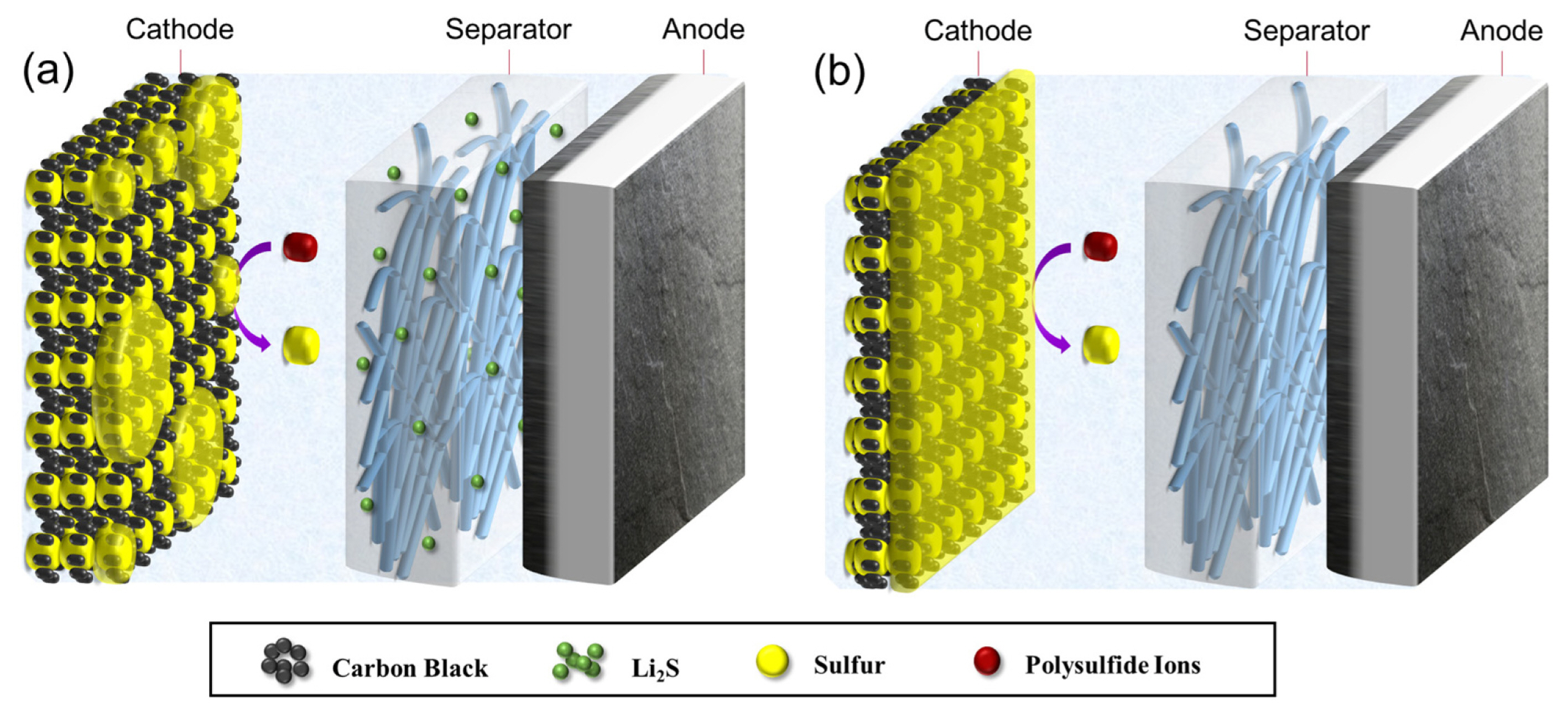
Based on this finding, it has been expected that the integration of a Li2S-impregnated separator to a conventional Li-S battery would have following effects: (1) generation of a significant amount of medium order polysulfides via a well-known chemical reaction of solid Li2S and sulfur molecules dissolved in the electrolyte solution (see Fig. 1b); (2) conversion of Li2S particles into sulfur through the reaction routes mentioned above upon charging, and (3) improvement of the areal capacity by supplying additional sulfur to the cathode.
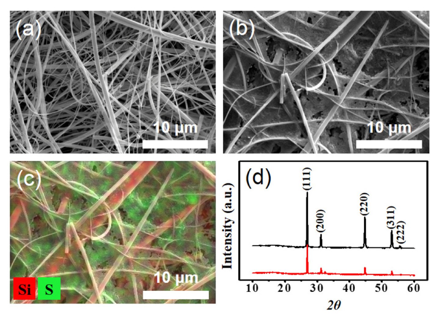
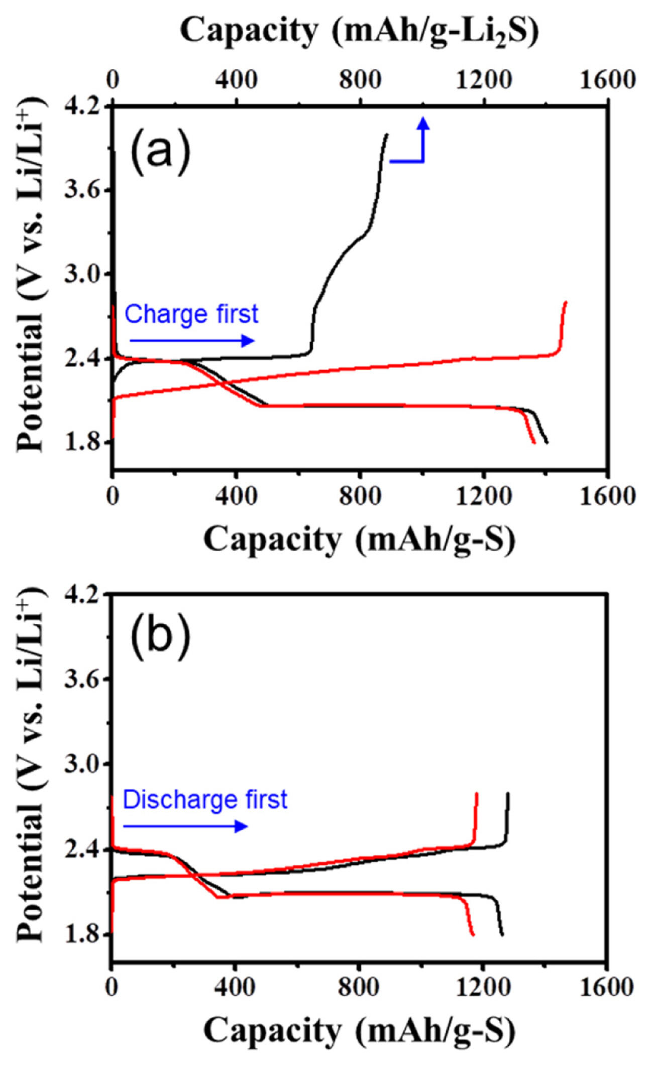
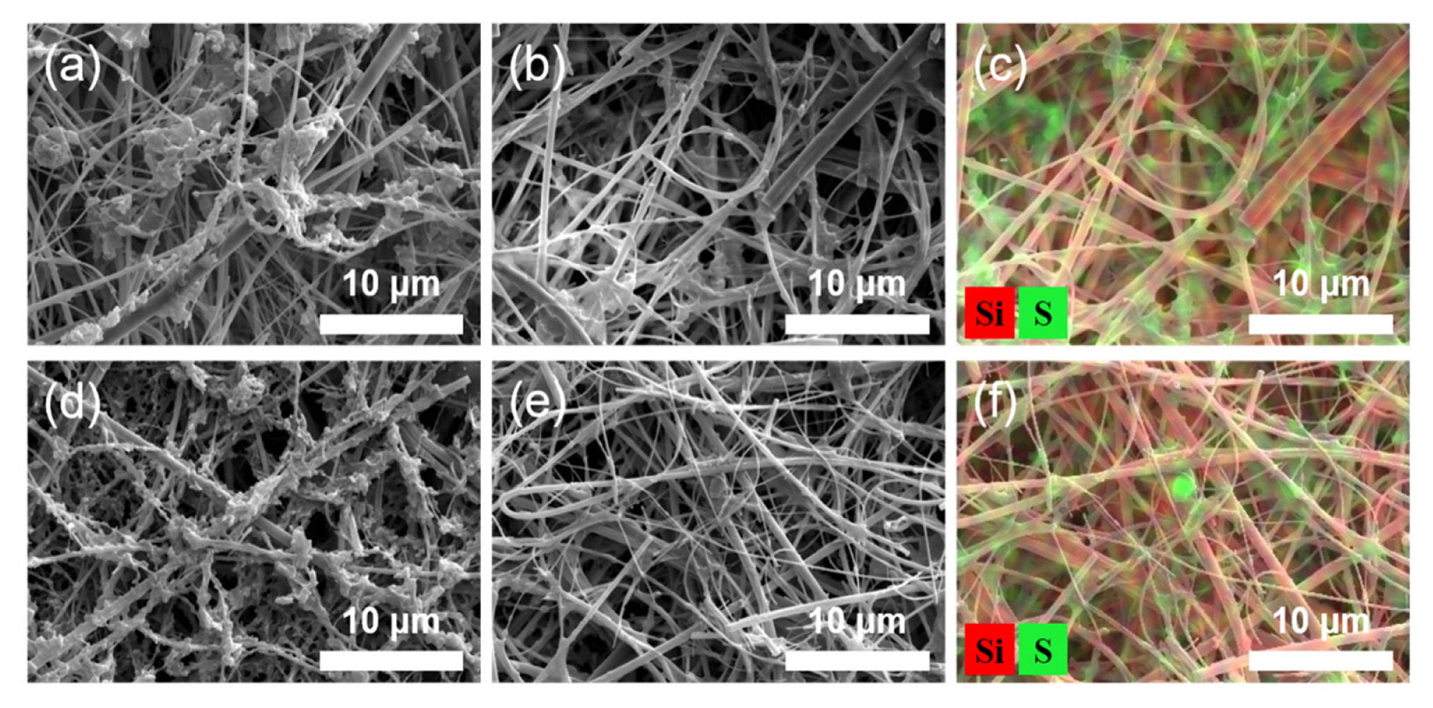
To verify this scenario, we constructed a new type of Li-S cell combining a Li2S-infiltrated glass fiber separator with a conventional sulfur cathode. The Li2S-infiltrated separator was prepared by soaking the pristine separator in the solution of Li2S in anhydrous ethanol (Fig. 1a). Fig. 2a and 2b show the SEM images of the surface of a pristine separator and the Li2S-incorporated separator. The pores of a glass fiber separator are observed to be uniformly filled with Li2S. The EDS elemental mapping results for S clearly show that Li2S is uniformly distributed in the micro-sized pores (Fig. 2c). To examine whether Li2S was successfully incorporated into a separator without exposure to moisture and oxygen, XRD analysis was carried out on the prepared Li2S-embedded separator. Measured XRD pattern well agreed with that of pure Li2S powder (Fig. 2d), indicating that the chemical nature of Li2S remained intact. To provide additional active materials to the sulfur cathode by converting Li2S to sulfur, Li-S cells with Li2S-filled separator were charged to 4.0 V after cell fabrication. The cell delivered a considerable charge capacity of ~865 mAh/g-Li2S with a distinctive charging profile (Fig. 3a). This confirms that a large portion of Li2S within the separator was oxidized to sulfur during the first charge. The potential profile can be divided into two parts with a breakpoint at around 75% of the charging process: (1) a long flat plateau region at ~2.4 V, and (2) a sulfur formation region with extremely high overpotential. This feature is clearly distinguishable from those of previous works involving coarse Li2S particles, where sharply rising potential curves were observed at the beginning of the first charge.
Yang et al. reported that the micro-sized Li2S/carbon black cathode showed a high overpotential at the beginning of charging for Li2S [25]. There, the authors explained that the large overpotential may arise from the strong bond between Li+ and S2− ions [25].
In a previous study, we showed a Li-S cell composed of a sulfur-free carbon cathode, Li2S placed between two separators and a lithium anode exhibits a significant overpotential during the entire charging process [23]. This observation indicates that the reaction rate of the cell was significantly restricted. We suggest that the slow kinetics corresponds to the chemical reactions of Li2S and high order polysulfides, and the long-distance mass transport of polysulfides between the carbon electrode surface and Li2S particles [23]. In particular, the steeply rising potential at the onset of charging is attributed to the significantly low concentration of medium order polysulfides.
In contrast, a long flat plateau (~2.4 V) without any potential spike was observed at the initial stage of charging in this work (Fig. 3a), even though large Li2S particles electrically isolated from the sulfur cathode were included in the cell. This can be explained by the chemical reaction of Li2S in separator and sulfur molecules in the electrolyte (see Fig. 1b). Due to the presence of molecular sulfur in the cell, considerable amount of medium-order polysulfides (e.g., Li2S3 and Li2S4) are produced and promote the electrochemical reactions.
In the second part of the first charge, the cell potential rose rapidly from 2.4 V to 4.0 V. This potential increase implies that the formation of sulfur induces a significantly larger higher overpotential (Fig. 3a). Since Li2S materials are placed in the electrolyte region away from the cathode, most of polysulfides exist outside the cathode and undergo oxidation reactions preferentially at the outer surface of the cathode. As sulfur formed participates on the cathode surface, the active sites (i.e., the surfaces of carbon particles) are covered with insulating sulfur and electrolyte access is significantly restricted by sulfur deposition at the cathode surface (See Fig. 4a). Such sulfur precipitates make further oxidation of the high-order polysulfides to sulfur at the cathode surface difficult, thereby causing a large overpotential. We expect that most reaction sites near the outer surface of the cathode would be blocked against the further charge transfer reaction at the end of the charge process, as shown in Fig. 4b.
Subsequently, the cells were discharged to a lower cut-off voltage of 1.8 V at a current of 0.05 C. The cells with the Li2S-incorporated separator delivered higher capacities than the control cell due to additional sulfur produced during the first charge (Fig. 3). However, the increase in the discharge capacities was found to be much lower than the charge capacities (~865 mAh/g) of Li2S. This can be ascribed to the low utilization of the sulfur that was mainly formed at the sulfur cathode surface. We think that the long-chain polysulfides, resulting from deposited sulfur on the cathode surface upon discharge, may diffuse more easily towards the lithium anode, thus limiting their further reduction.
In the following cycles, the cell with the Li2S-impregnated separator showed extra capacity with potential profiles similar to the control cell (Fig. 3a). This is in good agreement with previous results [23,25]. Above all, this demonstrates that by simple addition of the Li2S-embedded separator, a high loading cathode can be achieved, resulting in improving the capacities of Li-S cells.
The electrochemical oxidation of the Li2S materials in the separator was scrutinized by post-mortem analysis of the cells collected at the end of the first charge. The separator washed with DME clearly show that a substantial amount of sulfur precipitated on the surface of separator due to its poor solubility (Fig. 5a). Presumably, this is likely due to sulfur formed in the electrolyte region via the chemical reaction (4S82− → S8 + 4S62−) of polysulfides. To remove sulfur from the separator, it was rinsed several times with CS2. SEM image of the as-prepared Li2S-embedded separator shows that a large amount of Li2S had been consumed during the first charge (Fig. 5b), which is in line with the electrochemical data obtained in the first charge. Although, EDS elemental mapping result reveals that a noticeable amount of Li2S remained within the separator (Fig. 5c). We thus investigated the amount of unreacted Li2S at end of the second charge. The fine structure of the glass fiber separator was clearly visible (Fig. 5d and 5e), and the number of sulfur agglomerates was significantly reduced (Fig. 5f), indicating that that most of the Li2S materials had been consumed amidst the second charge.
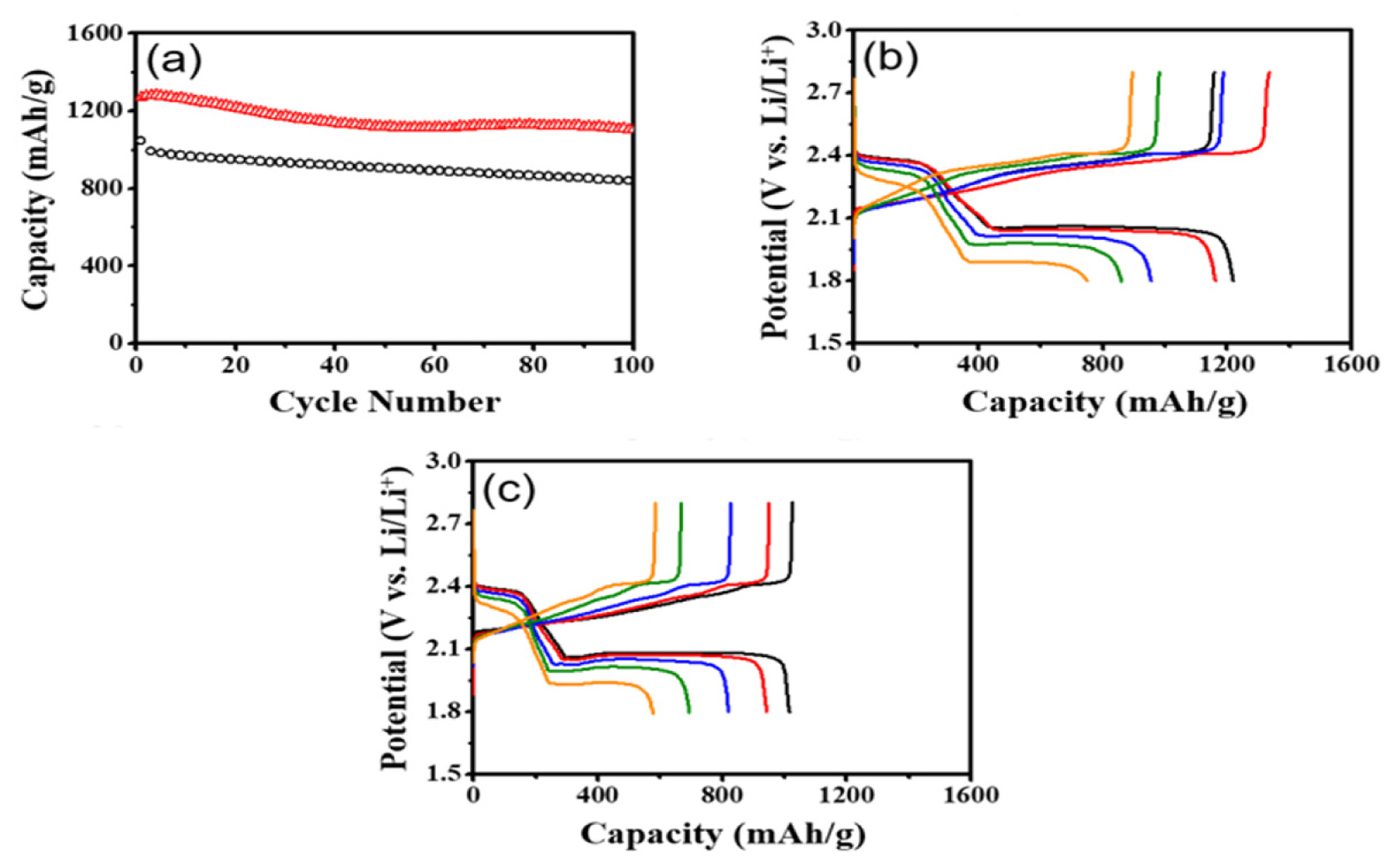
Furthermore, we evaluated the cycling stability and rate capability of the cell with the Li2S impregnated separator. The cell with Li2S exhibited significantly larger capacities of ~1100 mAh/g with an excellent capacity retention of 87% after 100 cycles than those (~840 mAh/g) of the control cell (Fig. 6a). This feature may stem from the change in utilization of extra active materials. The long-chain polysulfides generated from the reduction of extra S on the external surface of the cathode may migrate towards the lithium anode during the first discharge. In result, considerable amount of active materials are present between the cathode and the anode. During subsequent cycling, however, active materials in the electrolyte region are gradually absorbed within the cathode, resulting in enhanced utilization of extra sulfur materials as evidenced by the slight capacity increase in the beginning of cycle test. In contrast, the control cell exhibited typical capacity fading due to the ongoing loss of active materials during cycling.
In addition, high capacity retention at high rates was observed in the cell. The discharge capacities were as high as 1220, 1162, 955, and 860 mAh/g at 0.1 C, 0.2 C, 0.5 C, and 1 C, respectively (Fig. 6b). In particular, the cell with Li2S delivered a much higher capacity (751 mAh/g) at 2 C, compared with the control cell (Fig. 6b and 6c). This result can be explained by the same reason mentioned above: practical utilization of extra S increases for subsequent cycles as more active materials are involved in the electrochemical reactions. Overall the cell adopting the Li2S-embedded separator along with the sulfur cathode outperforms the control cell in terms of cycle life and rate property. This unambiguously demonstrates that the simple addition of Li2S-impregnated separator significantly improves the electrochemical performances of Li-S cells.
4. Conclusions
In this work, we present a new cell design for a high-performance Li-S battery. A Li2S-impregnated separator was sandwiched between a common sulfur cathode and a lithium anode. Li2S was found to be homogeneously distributed within the pores of the separator. The cell containing Li2S exhibits a much larger discharge capacity (1402 mAh/g) compared with a control cell without Li2S. SEM and EDS analysis of the separator after the second charge confirmed that most of Li2S is consumed and finally oxidized to sulfur during the second charge. Although the micron-sized Li2S particles are electrically isolated from the cathode, the Li-S cell was charged without an initial potential peak at the beginning of the first charge, as it had been observed in the cathode with micron-sized Li2S particles. This is ascribed to the presence of a large amount of medium-order polysulfides, which are formed by the chemical reaction between solid Li2S and dissolved molecular sulfur in the electrolyte. Moreover, the cell with Li2S outperforms the control cell regarding cycling stability and rate performance. This confirms the validity of our cell design strategy. We expect the performances of the cell to be further improved by optimization of key design parameters (e.g., thickness and pore structure of a separator, the content of Li2S in a separator, and the structure of a sulfur cathode). Owing to its simplicity, we believe that our design is suitable for the development of cost-effective and high-energy-density Li-S batteries.
 ).
).
 ) and the control cell without Li2S (○). Rate performances of the prepared Li-S cells: (b) the Li-S cell with Li2S and (c) the control cell at different current densities of 0.1 C (―), 0.2 C (
 ), 1.0 C (
 ), and 2.0 C (
 ).
).