1. Introduction
Highly-ordered anodic TiO2 nanotubes, which can be produced by simple electrochemical oxidation of Ti in F−-based electrolytes, have been widely used in various applications such as photocatalytic pollutant degradation [1–3], water splitting [4,5], dye-sensitized solar cells [6,7] biomaterials for implants [8] high cycling retention Li ion batteries [9,10], and so on.
Since through-hole anodic TiO2 membranes can effectively enhance the physical properties of devices in energy and environmental fields, [11] several methods have been developed based on ultrasonic-assisted separation, [12] solvent evaporation, [13] selective dissolution of metallic Ti in CH3OH/Br2, [1] voltage decreasing, [14] and voltage increasing (potential shock) [15]. In addition, doping of foreign elements into TiO2 nanotubes has been reported as an alternative method to tailor the physical properties of TiO2 [16–18]. For example, water splitting for hydrogen generation was enhanced in anodic TiO2 nanotubes containing RuO2 catalysts, [16–18] and electrochromic performance was dramatically improved by the doping of WO3 into TiO2 nanotubes [19]. Using the potential shock process, where a high anodic voltage is applied suddenly for a short period of time (e.g., 140 V for 10 s) immediately after the fabrication of nanotubes, can produce either through-hole membranes in an F−-containing electrolyte (MPS, membrane potential shock) [15] or metal oxide doping (DPS, doping potential shock) in negatively-charged dopant precursors [16–18]. Thus, electrolytes are very important factors to make either the membranes or doping of TiO2 nanotubes. In addition, a newly-grown thick barrier oxide is unavoidably formed if the potential of DPS is above 100 V, which prevents easy formation of completely through-hole TiO2 in MPS [16]. Thus, the optimized combination of potential shock is necessary to produce through-hole TiO2 containing functional catalysts.
In this report, we suggest an effective way to produce through-hole RuO2-doped TiO2 membranes by a simple electrochemical method, which can be easily applied to through-hole TiO2 nanotube membranes with a doping of other catalysts.
2. Experimental
Ti foil (0.127-mm-thick, 99.7% purity, Sigma-Aldrich) was cleaned with acetone, ethanol, and distilled water (DI) via ultra-sonication for 15 min, 10 min, and 5 min, respectively. The foil was subsequently dried in an oven at 60°C overnight. Anodization was conducted at 40 V for 2 h at room temperature using a power supply (source meter 2400, Keithley) in a two-electrode-type electrochemical cell. The electrolyte consisted of ethylene glycol (EG, Sigma-Aldrich), 0.25 wt. % ammonium fluoride (NH4F, Sigma-Aldrich), and 1 vol. % DI. The TiO2 nanotubes that were prepared initially were mechanically eliminated with epoxy [20], and a second anodization was carried out on the same Ti foil. In the case of DPS (Fig. 1 (a)), a second anodization was carried out in the electrolyte that was used during the first anodization at 40 V for 3 h. Subsequently, an anodic voltage (140 V for 10 s) was imposed on the nanotubes for doping in 0.002 M KRuO4 [17]. During single-step anodization doping (SSA) (Fig. 1 (b)), the second anodization was carried out in ethylene glycol, 0.25 wt. % ammonium fluoride, 1 vol. % DI, and 0.002 M KRuO4 (purity 97%, Sigma-Aldrich) for simultaneous fabrication and RuO2-doping of TiO2 nanotubes. Anodization was carried out at 40 V for 3 h at room temperature. For the fabrication of through-hole membranes, a constant high voltage (ranging from 100 to 180 V for 10 s) was imposed on the RuO2-doped nanotubular TiO2 in the F−-based solution (MPS). The electrolyte for MPS was the same as the one used in the first anodizing solution, in which fluoride ions drilled the bottom of the RuO2-doped TiO2 nanotubes. The morphologies of the fabricated TiO2 membrane were examined by a field-emission scanning electron microscope (FESEM, 4300SE, Hitachi, Japan). The presence of ruthenium ions in the membrane was confirmed by energy dispersive X-ray spectroscopy (EDX, 4300SE, Hitachi, Japan) and X-ray photoelectron spectroscopy (XPS, VGESCALAB 220i-XL spectrometer, Fisons, Al-Kα X-ray source). For the XPS measurements, nanotubes were detected from a Ti substrate, and the bottom sides of the nanotubes were measured to confirm that RuO2 doped both the surface of the nanotubes and also inside of the TiO2.
3. Results and Discussion
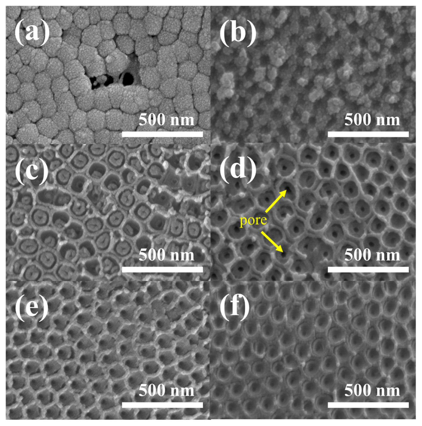
Fig. 1 shows the two processes used to produce through-hole RuO2-doped TiO2 membranes. In the first method (Fig. 1 (a)), potential shock was applied twice for the doping (DPS) and through-hole membrane (MPS) processes. In the case of DPS, a negatively-charged dopant (RuO4−) was used, whereas aggressive F− ions were employed for MPS. Since a thick barrier oxide is formed during DPS [18], through-hole membranes are not easily obtained, even at a high voltage in the subsequent MPS process (see Fig. 2 (a)). It has been well established that barrier oxide is newly grown on the bottom of TiO2, which is linearly increased by the potential of DPS, leading to less effective catalytic properties. In addition, further higher potential shock (for example, 200 V) leads to formation of voids in the oxide film, which further increases overpotential for electrochemical catalytic reactions [17].
Thus, SSA was employed as an alternative second method to avoid the formation of additional barrier oxide layer. Note that SSA is known as the method to dope the foreign catalysts into the TiO2 films without the formation of barrier oxides. Instead, the thickness of nanotube wall is increased up to more than twice, compared to that obtained under conventional anodization [18,21].
Since anodic nanotubes were simultaneously grown and doped with RuO2 and thick barrier oxide growth could be avoided during SSA, [16] the formation of through-hole membranes is possible in the subsequent MPS process. For example, through-hole membranes are clearly obtained on the RuO2-doped TiO2 nanotubes in Figs. 2 (b-f). The through-hole membrane prepared at 140 V shows the clearest hole on the barrier oxide (Fig. 2 d), whereas unclear openings on the barrier oxide are exhibited at potential shock voltages lower or higher than the optimized value [15,17]. Please notice that the potential shock time for making the through-hole TiO2 membranes from the pristine non-doped TiO2 nanotubes was optimized for 10 s [15]. Herein, since the thickness of barrier oxide is little increased when the TiO2 is doped by SSA, the potential shock time was optimized for 10 s. In fact, 5 s did not entirely open the bottom of pores.
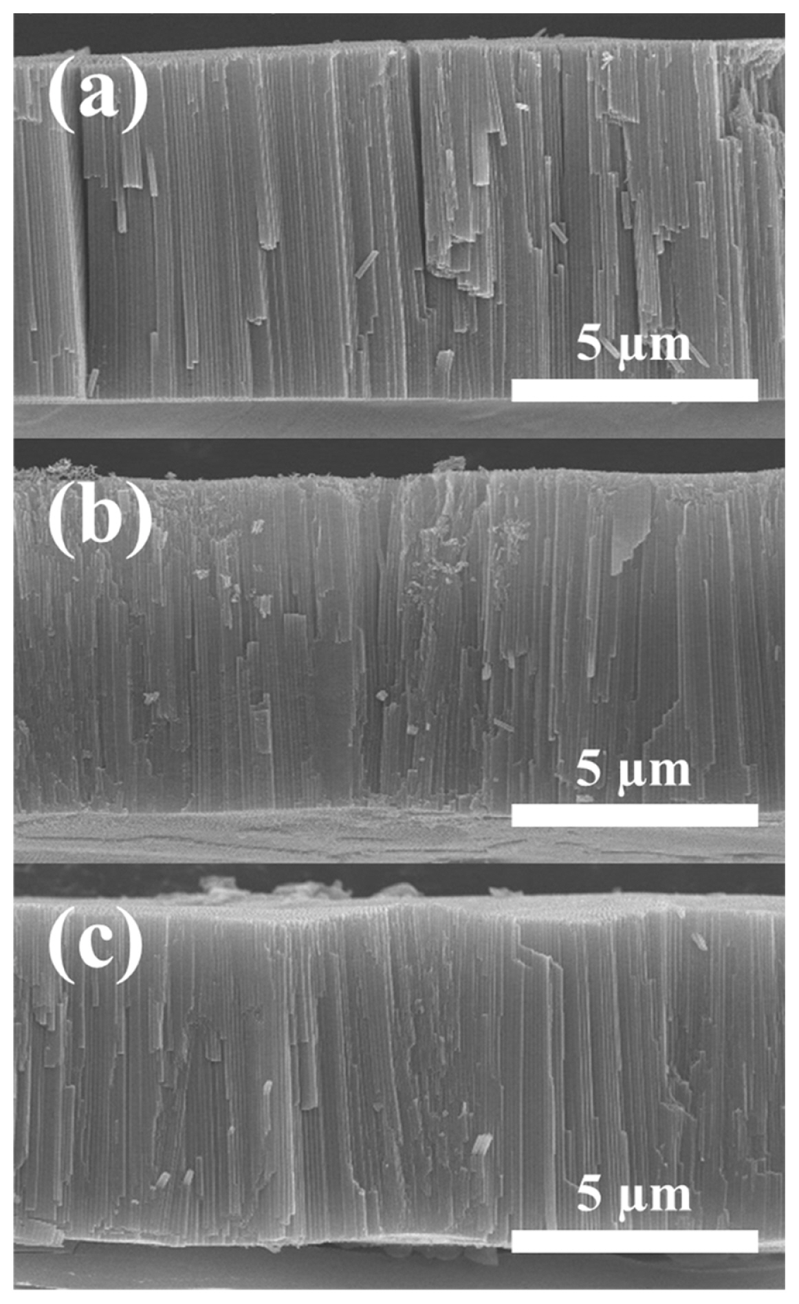
Fig. 3 shows the cross-sectional view of through-hole membranes, demonstrating that any structural deformation on 9-μm-thick TiO2 membrane does not happen during MPS even at high voltage. The straight nanochannels were clearly observed on all the samples.
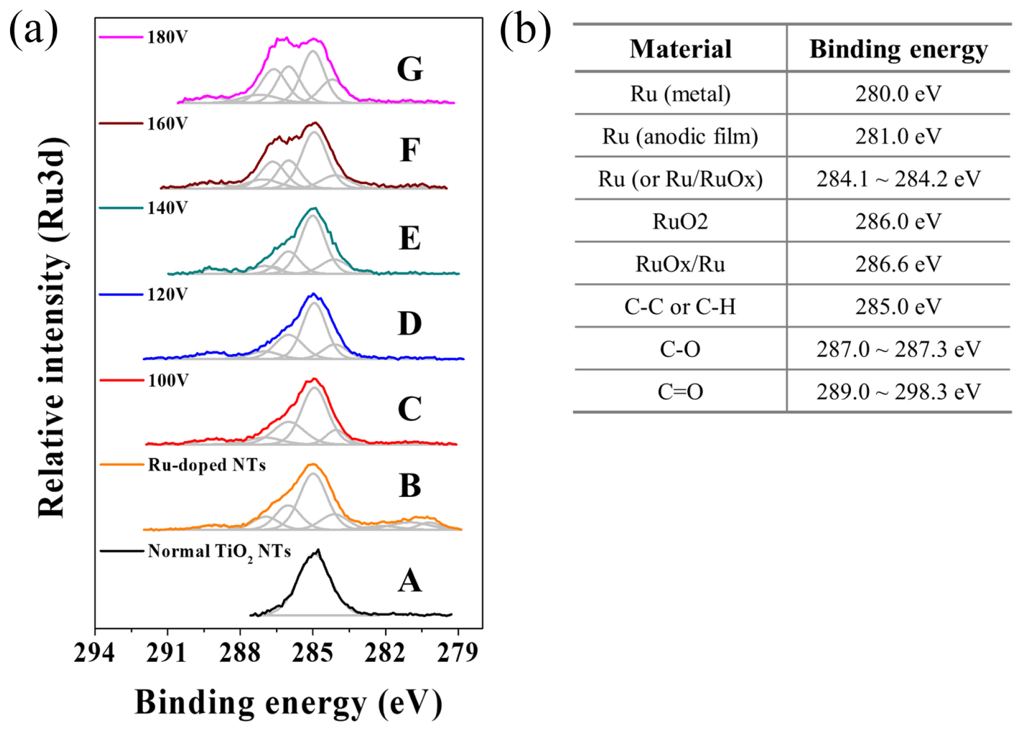
Fig. 4 confirms that the through-hole TiO2 membrane contains ruthenium oxides. Compared to non-doped TiO2 nanotubes showing C-C binding energy at 285 eV (Fig. 4 (a) A), peaks at 280 and 286 eV, which are attributed to Ru metal and RuO2, respectively, were detected on the as-prepared RuO2-doped TiO2 nanotubes made by SSA (Fig. 4 (a) B). The peak at 280 eV disappeared after MPS, indicating that the Ru metal was oxidized or dissolved in the electrolyte. Interestingly, as the MPS voltage increased, the peak intensity at 286 eV, which corresponds to RuO2, increased (Fig. 3 (a)). This indicates that the RuO2 inside of the TiO2 film moves deeply into the interface between the oxide and the Ti substrate during MPS. The peak at 288.6 eV, corresponding to RuOx/Ru, appeared above 140 V; this demonstrates that further increases in the MPS voltage led to the formation of multiple amorphous ruthenium oxides. All of the XPS results indicated that there was not a significant loss of ruthenium oxide in the TiO2 nanotubes during MPS. Thus, the suggested method is a reasonable way to produce through-hole-type catalyst-doped TiO2 nanotube membranes. In addition, we found that the morphology of the nanotubes is not destroyed, even after experiencing very high voltages during MPS.
4. Conclusions
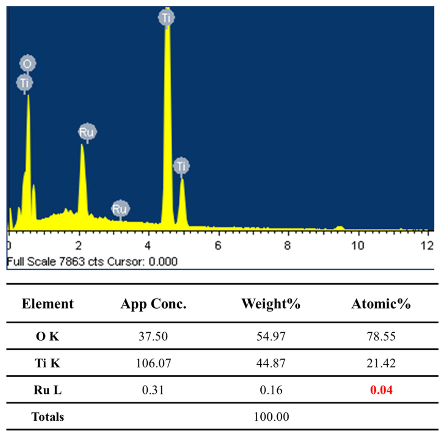
We demonstrated an effective method to produce through-hole TiO2 membranes containing a RuO2 catalyst. Since DPS produced a thick barrier oxide on the bottom of TiO2 nanotubes, subsequent MPS could not easily produce through-hole membranes, even at a high MPS voltage. Thus, doping RuO2 into the TiO2 nanotubes was carried out by SSA in an electrolyte containing a negatively-charged RuO4− precursor, which avoided forming a thick barrier oxide. Subsequent MPS at the optimized voltage (140 V in this study) led to the formation of through-hole RuO2-doped TiO2 membranes. In the XPS analysis of the bottom sides of TiO2 nanotubes, peaks at 286 and 286.6 eV were observed. These were attributed to RuO2 and RuOx/Ru, respectively, and clearly confirmed that RuO2-doped TiO2 nanotubes were successfully formed by the suggested method. EDX analysis showed that 0.04 at% Ru is successfully doped into TiO2 nanotubes.