


1. Introduction
As our demand for electrical power grows, it becomes increasingly urgent to find new ways of meeting it both responsibly and safely. Of various fuel cell systems available, the microfluidic membraneless fuel cells have been recognized as one of the most promising candidate for small-scale portable power applications [1-4]. A membraneless fuel cell is a well known electrochemical device that enables the conversion of chemical energy of fuels directly into electrical energy without a membrane as long as the fuel is supplied. Membraneless micro fuel cells use liquid reactants (fuel and oxidant) that flow side by side in a laminar fashion in a single channel without a membrane [5].
In this study, membraneless sodium perborate fuel cell (MLSPBFC) employs an alkaline solution of hydrazine as a fuel and an acidic solution of sodium perborate (NaBO3. 4H2O), as an oxidant. All the aforementioned membrane-related issues can be avoided in the MLSPBFC studied here. The performance implications of operating fuel cell under ŌĆ£alkaline-acid mediaŌĆØ, i.e. one electrode is acidic and the other is alkaline is the focus of our study. Sodium perborate is an environmentally friendly, cheap, nontoxic, large scale industrial chemical used primarily in detergents and as a mild oxidant. Sodium perborate is a true peroxo salt and is a convenient source of hydrogen peroxide [6,7].

As mentioned in our earlier study, the sodium perborate fuel cell is unique from other fuel cells using H2O2, as it can be used not only as an oxidant but also as a reductant [8,9]. On the performance side, the membraneless sodium perborate fuel cell generates electric power comparable to a typical air breathing direct methanol fuel cell when operating in a microchemical channel at room temperature. In addition, the membraneless sodium perborate fuel cell requires no membrane electrode assemblies. Thus, the cost for the materials is low and the structure of the cell is simple. With these advantages, membraneless sodium perborate fuel cells (MLSPBFC) can be used as an alternative for portable power applications.
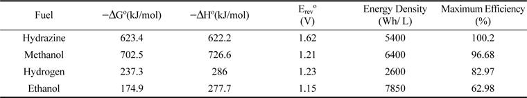
Hydrazine (N2H4) is a low cost material and its synthesis is relatively simple. Hydrazine is composed of only hydrogen and nitrogen; theoretically, the anode reaction produces only nitrogen. Therefore perfect zero emission equal to a pure hydrogen fuel can be realized [10]. The absence of carbon atom in hydrazine leads to zero production of species that may poison the electrocatalysts [11]. Compared with ethanol, methanol, hydrogen and V2+, hydrazine has a higher overall theoretical open circuit potential and maximum efficiency as indicated in Table1. In addition, studies have shown that the hydrazine electro-oxidation process does not suffer from any poisoning effect [12,13]. In sum, hydrazine seems to be a promising fuel for fuel cells and thus has been explored by us as the fuel with the membraneless fuel cell in this paper.
In this study, we have attempted to use sodium perborate as the oxidizer to develop a new type of hydrazine- based membraneless fuel cell. The unsupported pt black nanoparticle was fabricated and used as the catalyst for perborate electroreduction reaction. The influence of anolyte and catholyte on cell voltage and cell performance was studied. The effect of media (Alkaline-acid) flexibility and the electrode polarization were evaluated. This development was based on our previous results regarding the electro-oxidation of methanol in acid-alkaline media.[14].
2. Experiments
2.1 Materials and reagents
All experiments were conducted at room temperature using hydrazine (98%, Merck) in de-ionized water as the fuel, and sodium perborate (99%, Riedel) dissolved in 0.5 M sulfuric acid (98%, Merck) or 0.5 M Sodium hydroxide (98%, Merck) in de-ionized water as the oxidant.
2.1.1 Catalyst deposition
For all the experiments of MLSPBFC, unsupported platinum black nanoparticles are used as a catalyst for cathode and anode that line the microfluidic channel. The catalyst suspensions for both anode and cathode were prepared by mixing at a concentration of 6.0 mg-1 Pt black nanoparticles (Alpha Aesar) in a 10 wt% Nafion solution (Nafion stock solution: Dupont 5% (w/w)solution). This mixture was sonicated and applied to the inner walls of the graphite plates that line the microfluidic channel, at a loading of 2 mg cm-2. The solvent was then evaporated by using a heat lamp for uniform loading.
2.1.2 Design of membraneless sodium perborate fuel cells (MLSPBFC):
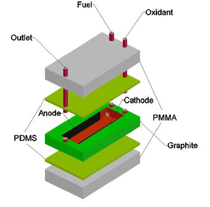
In the MLSPBFC configuration, a laminar flow channel with catalyst-coated graphite plates of 1 mm thickness is used. Unsupported platinum black nanoparticles are electrodeposited to the sides of the graphite plates that act as anode and cathode and line the microfluidic channel. With the subsequent deposition of catalyst to the cathode and anode, the microfluidic channel structure is moulded with PDMS poly(dimethylsiloxane), typically 1-10 mm in thickness, and finally sealed with a solid substrate such as 2 mm thick pieces of PMMA poly(methylmethacrylate) to provide rigidity and strength to the layered system. Silicon tubing is used to guide the fuel and oxidant into the microfluidic channel systems at the top and to guide the waste stream out at the bottom of the channel Fig. 1.
2.2 Test of the fuel cell
The fuel and oxidant solutions were pumped through the device using a syringe pump (Schiller India). The flow rate of each of the streams was 0.3 mL min1 (total flow rate of 0.6 mL min1). Also, the cell was allowed to run for an hour for the flow to reach a steady state. In multistream laminar flow, two or more liquid streams merge into a single microfluidic channel (Fig. 2), and continue to flow laminarly in parallel without turbulent mixing, if the system is characterized by a Reynolds number, Re < ~2100 [15]. In the previous work, we were able to show that this phenomenon can be utilized to create a membraneless micro fuel cell by merging two streams, one containing fuel (Hydrazine) and one oxidant (sodium perborate), respectively, and allowing these streams to flow over the anode and cathode electrodes placed on opposing side walls within the microfluidic channel [16,17]. Fuel and oxidant react at the electrodes while the two liquid streams and their common liquid-liquid interface provide the required ionic conductance to complete the fuel cell chemistries.
Fig.┬Ā2.
A cross section of channel showing depletion boundary layer over anode and cathode metal catalyst and inter diffusion zone at the liquid-liquid interface with vertical electrodes on side walls.
Cell measurements were recorded using a CS310 computer controlled potentiostat (Zhengzhou triangle instrument Co. Ltd.) with the associated Thales Z software package. For each analyzed factor, the performance of the fuel cell was evaluated by recording the cell polarisation and obtaining the corresponding power density curves. Consequently, the microfluidic cell was found to keep these fluids stable without a separation membrane.
2.3 Alkaline-acid media flexibility of membraneless sodium perborate fuel cell
This membraneless micro fabrication method eliminates several of the technical issues related to the use of polymer electrolyte membrane fuel cells (PEMs) [18,19]. In addition, lack of a membrane also allows for operation of MLSPBFCs in more than one media. Moreover, the chemical composition of the cathode and anode streams can be designed individually to optimize individual electrode kinetics as well as overall cell potential. Furthermore, the MLSPBFC has the flexibility to run in all-acidic, all-alkaline, or in an ŌĆ£Alkaline-acid mediaŌĆØ mode in which the anode is exposed to acidic media while the cathode is exposed to alkaline media, or vice versa. The performance of MLSPBFC in Alkaline-acid media configuration, using an alkaline anode and an acidic cathode was higher overall cell potential than what was obtained from all-acidic and all-alkaline fuel cell experiments.
3. Results and discussion
Two different approaches have been pursued: the first step consisted in analysing the flexibility and performance implications of operating membraneless sodium perborate fuel cell (MLSPBFC) in an alkaline-acid media and the subsequent second step was intended to further improve the cell performance by characterising the main cell by changing several operational parameters, such as fuels compositions, oxidant compositions, electrolyte compositions, distance effect and flow rate, and to observe their influence on the polarisation behaviour of the cell.
3.1.1 Performance of MLSPBFC in all-acidic and all-alkaline media
The pH of the electrolyte influences reaction kinetics at the individual electrodes, as well as the electrode potential at which oxidation or reduction occurs [20-24]. Equations (2) and (3) represent the half-cell reactions and standard electrode potential of hydrazine oxidation and peroxide reduction in acidic media and the Equations (5) and (6) represent the alkaline media. Equations (4) and (7) represent the overall cell reaction, in all-acidic and all alkaline media. The acidic-acidic media and the alkaline-alkaline media have a maximum theoretical open circuit potential (OCP) of 1.56 V and 2.156 V respectively. On the other hand, we use the bipolar electrolyte to force reactions (3) and (5) to achieve further improvement in fuel cell performance.


3.1.3 Hydrazine / Perborate in Alkaline Medium:


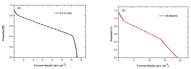
A comparison of the performance of an MLSPBFC in all-acidic and all alkaline media is exhibited in Figs. 3a and 3b respectively. Initially at low current densities, both the polarization curves are identical and thus it is clear that the performance of MLSPBFC is independent of the medium. The mass transport limitation region is around 6 mA cm-2 in the MLSPBFC running for both acidic and alkaline media was in agreement with the previous study [25]. The MLSPBFC worked for several days without any drop in its performance in a vast array of test conditions.
Fig.┬Ā3.
Polarisation curves for overall cell performance of MLSPBFC operating in: (a) all acidic and (b) all alkaline media at room temperature. For both experiments the fuel stream is 0.075 M hydrazine + 0.5 NaOH (a) and in 0.5 M H2SO4 (b) and the oxidant streams is 0.1 perborate + 0.5 M NaOH (a) and 0.5 M H2SO4 (b). Stream flow rates: 0.3 mL min-1.
3.2 Performance of MLSPBFC in Alkaline-acid media 1: acidic anode, alkaline cathode:
The performance of MLSPBFC using a fuel stream of 0.075 M Hydrazine in 0.5M H2SO4 and an oxidant stream of 0.1M Perborate in 0.5M NaOH was investigated. The measurements were taken at room temperature for two configurations: Alkaline-acid media 1: acidic anode, alkaline cathode and alkaline-acid media 2: alkaline anode, acidic cathode. In these Alkalineacid media configurations the neutralization reaction of OH- and H+ to water occurs at the liquid-liquid interface between the fuel and oxidant streams. In the first configuration, the overall cell reaction, Eq. (8), can be obtained from Eqs. (2) and (6):
3.2.1 Alkaline-acid media 1: Acidic Anode & Alkaline Cathode:


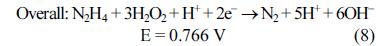
In this alkaline-acid media configuration 1, the maximum theoretical OCP that can be obtained is 0.766 V. The energy liberated in hydrazine oxidation and peroxide reduction reactions is mostly consumed by the water ionization reaction. In this configuration, coexistence of the galvanic and hydrazine electrolytic reactions has been found to be the reason why useful amounts of energy could not be yielded, and why it was not studied any further.
3.3 Performance of MLSPBFC in Alkaline-acid media 2: alkaline anode, acidic cathode:
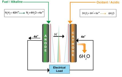
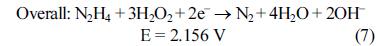
In contrast, in alkaline-acid media configuration 2, the MLSPBFC using a fuel stream of an alkaline anode and an acidic cathode allows energy to be obtained both from the Hydrazine oxidation/peroxide reduction reactions and from the acid/alkaline electrochemical neutralization reactions, as evident from the overall cell reaction Eq.(9):
3.3.1 Mixed Media 2: Alkaline Anode and Acidic Cathode:

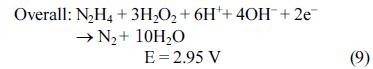
In this Alkaline-acid media 2 configuration, the combination of two galvanic reactions yields a desirable high theoretical OCP of 2.95 V. Note that the inherent value of the electromotive force of the MLSPBFC is higher than that of the HFC (1.23 V) and the PEMFC or DMFC (1.21 V). However, because of the over potential resulting from the slow kinetics of peroxide reduction and hydrazine oxidation, the open circuit potential is reduced to a measured value of 1.72 V as shown in Fig. 4. In the Alkaline-acid media configuration both OHŌłÆ and H+ are consumed at the anode and cathode, respectively, at a rate of four for each molecule of hydrazine.
Fig.┬Ā4.
Performance of media flexibility on current and power density of MLSPBFC at room temperature. a) All acidic [Fuel]: 0.075M hydrazine + 0.5M H2SO4. [Oxidant]: 0.1M perborate + 0.5M H2SO4, b) All alkaline [Fuel]: 0.075M hydrazine + 0.5M NaOH. [Oxidant]: 0.1M perborate + 0.5M NaOH. c) Alkaline-acid media [Fuel]: 0.075M hydrazine + 0.5M NaOH. [Oxidant]: 0.1M perborate + 0.5M H2SO4.
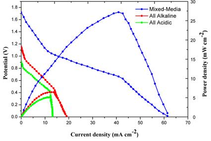
The MLSPBFC can thus be run in a mixed-media configuration in which the anode can be alkaline while the cathode is acidic, or vice versa, to improve individual electrode kinetics and thermodynamics. The MLSPBFC operated in the alkaline anode/acidic cathode mixed-media configuration, a large OCP of 1.72 V was measured, which, in light of the known overpotentials at both the cathode and the anode, is in good agreement with the theoretical OCP of 2.95 V. These large potentials result in a rather unusual phenomenon for fuel cells; at high current densities, once the oxygen has been depleted from the oxidant stream, proton reduction becomes the cathode reaction [25,26]. Operating in this Alkaline-acid media configuration, with an alkaline anode and an acidic cathode, resulted in a higher overall cell potential than those obtained for the all acidic and all- alkaline MLSPBFC experiments. In MLSPBFC, the all-acidic and all-alkaline experiments have maximum power densities of 5.2 and 6.4 mW cmŌłÆ2 respectively, both at a cell potential of about 0.91 V, 1.16 V whereas the Alkaline-acid media experiment results in a power density maximum of 27.2 mW cm-2 at a cell potential of about 1.72 V. Within this condition, the Alkaline- acid media fuel cell clearly outperforms both the all acidic and all-alkaline fuel cell. The higher power densities in the Alkaline-acid media MLSPBFC are a direct result of higher overall cell potentials due to the unprecedented ability to operate the cathode and anode at different pH in an MLSPBFC.
3.4 Influence of fuel composition
The effect of fuel on the performance of MLSPBFC has been observed by varying the Hydrazine concentration between 0.025 M and 0.125 M as shown in Fig. 5.
Fig.┬Ā5.
Effect of hydrazine concentration on the current and power density of the MLSPBFC at room temperature. [Fuel]: x M hydrazine + 0.5 M NaOH. [Oxidant]: 0.1 M perborate + 0.5 M H2SO4.
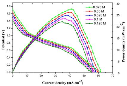
The experiment results show that the fuel cell performance decreases as the Hydrazine concentration increases. This decreasing trend in cell performance at higher hydrazine concentrations is due to four reasons i) creation of mixed potential at the cathode due to fuel crossover ii) kinetic decrease in anode iii) transport resistance increase at the anode iv) ohmic resistance increase.
In a fluidic system, fuel crossover can create mixed potential, decrease cell efficiency, and even deactivate the catalyst. Fortunately, the device design and operating parameters can be controlled so that fuel crossover can be prevented [27,28] in any membraneless fuel cell. Therefore higher hydrazine concentration is not the cause for decrease of performance in fuel cell. The kinetic decrease in anode also cannot be the reason because the electro-oxidation of hydrazine on Pt has a positive reaction order between 0.025 M and 0.075 M. The activity at the anode increases as the concentration of fuel increases. Therefore, the anode is not limited by kinetic performance with higher hydrazine concentration.
Also, mass transport resistance should actually decrease with increased hydrazine concentration. This is because a higher concentration would create a higher driving force for the hydrazine to diffuse across the depletion boundary layer to the electrode. This increases the ohmic resistance; hence, the protons cannot be transported efficiently and this leads to a poor cell performance. This is the only explanation for decreased cell performance with higher hydrazine concentrations. From these reasons, the 0.075M seems to be the best composition for the fuel; this value being fixed for the remaining experiments.
3.5 Influence of oxidant composition
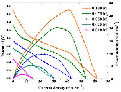
The effects of perborate concentration on the cell performance were investigated at 0.01, 0.025, 0.05, 0.075 and 0.1 M. The power density increased in correlation to increased sodium perborate concentration in the MLSPBFC system and reached the maximum of 1.72 V at 0.1 M sodium perborate. Peak power densities of 1.77, 5.28, 9.66, 20.30, 27.2 mW cmŌłÆ2 were obtained at 0.01, 0.025, 0.05 0.075 and 0.1 M respectively as shown in Fig. 6. Further increase in the oxidant concentration shows no improvement in the cell performance. Therefore, the value of 0.1 M has been fixed for the perborate concentration in the oxidant solution.
Fig.┬Ā6.
Effect of perborate concentration on the current and power density of the MLSPBFC at room temperature. [Fuel]: 0.075 M hydrazine + 0.5 M NaOH. [oxidant]: x M perborate + 0.5 M H2SO4 .
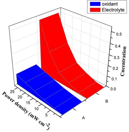
The effects of perborate and H2SO4 composition in the oxidant solution have also been analyzed. The H2SO4 concentration was varied between 0.01 M and 0.5 M. The maximum power density 27.2 mW cmŌłÆ2 was obtained at 0.5 M H2SO4 as shown in Fig. 7. Further increase in the H2SO4 concentration shows no improvement in the cell performance. Therefore, the value of 0.5 M has been fixed for the H2SO4 concentration in the oxidant solution.
Fig.┬Ā7.
Effect of various combinations of perborate and sulphuric acid concentrations on the maximum power density (27.2 mW cmŌłÆ2) of the MLSPBFC at room temperature. The fuel mixture for variation of oxidant is ([fuel]: 0.075 M hydrazine + 0.5 M NaOH, [oxidant]: x M perborate + 0.5 M H2SO4) and the fuel mixture for variation of sulphuric acid is ([fuel]: 0.075 M hydrazine + 0.5 M NaOH, [oxidant]: 0.1 M perborate + x M H2SO4).
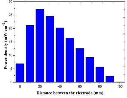
3.6 Influence of distance effect on the performance of MLSPBFC
In order to find the potential benefit from a reduced diffusion length of reacting species moving between the anode and cathode the fuel cell test was conducted to find between 1 to 100 mm. When the distance between the anode and cathode decreased from 100 to 20 mm, the maximum power density increased as shown in Fig. 8 and on further decrease in distance results in an increase in ohmic resistance, hence the fuel cell power also decreases. Considered the role of a charge carrier, a shorter diffusion length is believed to give a faster electrochemical reaction because the diffusion time of reacting species would be shorter. Therefore, more reactions can take place at a given time, which increases the total number of charges involving the electrochemical reactions at the anode and cathode. This finding provides good evidence of the presence of a charge carrier moving between the anode and cathode in the fuel mixture to complete redox reactions of the fuel cell [29].
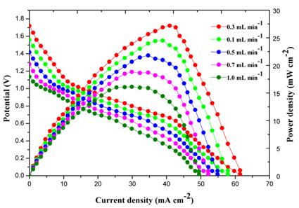
3.7 Influence of fuel mixture flow rate
Since maximum power density is dependent on the transport time of reacting species it can be controlled by its flow rates. In this experiment, flow rates of 0.1, 0.3, 0.5, 0.7 and 1.0 mL minŌłÆ1 were tested. The cell potential and current were measured with different external loads as a function of the flow velocity of fuel mixture. Using the flow rate applied and the cross sectional area of the channel, a flow velocity can be calculated. In this work, the maximum power density was obtained at about 0.3 mL minŌłÆ1. After that the maximum power density decreased with increase in flow rate as shown in Fig. 9. It is believed that more electrochemical reactions will take place in a given time and a greater output current can develop in the end. Lower flow rates result in enhanced fuel utilization and higher energy density. Higher flow rates have greater power densities but lower utilization [30]. It may be possible to increase the power at low flow rates without compromising utilization by increasing the concentration of the supporting electrolyte, increasing the surface area of the catalyst, or by using a fuel with greater electrochemical activity. The lower flow rate improves performance by increasing the reactant flux and by decreasing the concentration boundary layer thickness providing better reactant supply to the electrodes [31].
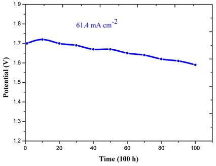
3.8 Stability test
Durability of the MLSPBFC was examined Shortterm stability of MLSPBFC under alkaline-acid media configurations was tested by monitoring the cell voltage change during the galvanostatic discharge of 61.4 mA cmŌłÆ2 of the MLSPBFC in a period of about 100 h (Fig. 10).The MLSPBFC maintained a relatively stable performance with a little decay of cell voltage over the test period. The fluctuation in the cell voltage was due to addition of the new fuel solution, restarting the experiments, or small variation in cell temperature. The result of the durability test showed that the MLSPBFC in our research has good stability at room temperature which is able to satisfy the necessary conditions as portable power sources.
4. Conclusions
A small scale membraneless sodium perborate fuel cell (MLSPBFC) was fabricated on PDMS and its operating behaviour were evaluated under different conditions. Standard microfabrication techniques were used to develop this device. Hydrazine is used as a fuel at the anode and sodium perborate is used as an oxidant at the cathode in this membraneless fuel cell under alkaline-acidic media. The experiments described in this study clearly indicate that membraneless sodium perborate fuel cells are media flexible and they can be operated in all-acidic, all-alkaline, or even combined alkaline-acidic media.
At room temperature, the laminar flow-based microfluidic fuel cell produced a maximum power density of 27.2 mWcmŌłÆ2. In the fuel cell, power density was found to increase with an increase in perborate concentration till 0.1M and above this concentration, a decrease in cell performance was noted. The variation of hydrazine concentration at the anode produced was found to have little influence on the cell performance. Thus, the present experimental results have confirmed that this membraneless microfuel cell is cathode-limited, and indicate that a crucial factor for improving cell performance is increasing the concentration of the oxidant in the cathode stream.
The flexibility of membraneless fuel cells to function with different media allowed for the successful working of mixed alkaline and acidic fuel cells. The membraneless microfuel cell system investigated in this study seems to be a good candidate having many potential applications because its performance is comparable to an air-breathing DMFC without CO2 emission.
The results demonstrated that the performance of the developed membraneless fuel cell is significantly enhanced if the concentration of the oxidant in the cathodic stream is 10 times larger, and the current density is also increased approximately 10 times.
The MLSPBFC proposed here is a conducive to novel based microfuel cells and future work will be driven toward the development of media flexible microfluidic fuel cells using suitable metal catalysts which in turn could have a wide range of applications in portable power electronic systems.
The MLSPBFC has the advantages of a miniature size, simplicity of fabrication, use of aqueous fuel, and good cost efficiency. Furthermore, perborate is a cheap, nontoxic, stable, easily handled, environmentfriendly, large-scale industrial chemical, and is a convenient source of hydrogen peroxide. We expect that the MLSPBFC promises to be the environmentally friendly power source of the future for portable power applications.


