The Role of Metal Catalyst on Water Permeation and Stability of BaCe0.8Y0.2O3-δ
Article information
Abstract
Perovskite type ceramic membranes which exhibit dual ion conduction (proton and oxygen ion conduction) can permeate water and can aid solving operational problems such as temperature gradient and carbon deposition associated with a working solid oxide fuel cell. From this point of view, it is crucial to reveal water transport mechanism and especially the nature of the surface sites that is necessary for water incorporation and evolution. BaCe0.8Y0.2O3-α (BCY20) was used as a model proton and oxygen ion conducting membrane in this work. Four different catalytically modified membrane configurations were used for the investigations and water flux was measured as a function of temperature. In addition, CO was introduced to the permeate side in order to test the stability of membrane against water and CO/CO2 and post operation analysis of used membranes were carried out. The results revealed that water incorporation occurs on any exposed electrolyte surface. However, the magnitude of water permeation changes depending on which membrane surface is catalytically modified. The platinum increases the water flux on the feed side whilst it decreases the flux on the permeate side. Water flux measurements suggest that platinum can block water permeation on the permeate side by reducing the access to the lattice oxygen in the surface layer.
1. Introduction
The world’s increasing concern about environment and descending of energy resources lead researchers to investigate cleaner and renewable energy production methods. One way of developing this kind of technology is the use of hydrogen as an energy carrier in fuel cells. Fuel cells can offer the world high energy conversion and low, even zero emission. Solid oxide fuel cell is one of the main kind of fuel cell technology which is the most promising sustainable clean energy converter. Perovskite type proton conductors have been taking much attention for solid oxide fuel cells lately owing to their intermediate working temperature and high ionic conductivity [1,2]. Yttrium-doped barium cerates have been recognised as the best high temperature proton conductors due to its high conductivity and selective water transport among others. Yttrium-doped barium cerates exhibit both proton and oxide ion conductivity at intermediate temperatures and create protonic defects in water vapour containing environments according to the reversible Wagner reaction shown below (in Kroger-Vink notation) [3-9].

Reaction 1 shows formation of protonic defects (OHO•) at the high water partial pressure surface. The protonic defects then travel through oxygen sites by hopping within the lattice. The recombination of protonic defects occur at the low water partial pressure surface according to reverse reaction 1 which create oxygen vacancies. The oxygen vacancies then diffuse back to high water partial pressure surface (Grotthuss mechanism) [5,6]. In a perovskite membrane the water permeation composes of adsorption of water from the gas phase to the membrane surface, water dissociation, bulk diffusion, water recombination (incorporation of hydroxide groups) and desorption of water.
Proton and oxygen ion conduction in these types of perovskite ceramics is studied by many researcher by means of ac impedance measurements [5,6,9-16]. Coors [16] carried out conductivity measurement of BaCe0.9Y0.1O3-δ (BCY10) in moist and dry helium and proposed a water permeation flux model. Water solubility of single crystals of yttrium and gadolinium doped BaCeO3 was studied using thermal gravimetric analysis (TGA) by Kreuer et al. [6]. Their result suggested that dopant distribution strongly affects water saturation limit. Ricote et al. [9] carried out similar study using BaCe(0.9-x)ZrxY0.1O(3-δ). They determined concentration of protons incorporated into the membranes via water uptake measurements at 400-600°C. The transport properties of BCY10 under different water partial pressure was also studied by Grimaud et al. [11] using Raman spectroscopy and calculated defect concentrations under humid air. The chemical diffusion of water in double perovskites Ba4Ca2Nb2O11 and Sr6Ta2O11 was investigates via hydration experiments by Animitsa et al. [10]. Although, there has been some research going on water permeation, his study will investigate and evaluate a different aspect of these materials which can be adopted as a water permeable electrolyte in fuel cells. This approach can assist to solve various operating problems. For instance, introduction of water to cathode instead of anode can eliminate fuel dilution, carbon deposition and temperature gradient (due to fast and endothermic reforming reactions versus slow and exothermic fuel cell reactions) in the cell. Permeation of water from cathode to anode can remove deposited carbon from anode surface as well as promoting hydrocarbon reforming when a hydrocarbon fuel is used in the anode [16,17].
Water permeation in such a device has not been investigated in any detail. The kinetic behaviour of this type of device, which could operate as a fuel cell and a water permeator, and more specifically the effect of electrodes on water permeation is not explored in detail to the best of author’s knowledge. For such an approach to be feasible it is crucial to understand water permeation mechanism, especially the nature of the surface sites that are necessary for water dissociation into the membrane as well as water incorporation. Such understanding will allow the rational design of water permeable fuel cell. This study investigates the impact of electrode modification on water permeation and tests stability of the membrane during water permeation and water-gas shift reactions via using different membrane modifications with platinum.
2. Experimental
The commercially obtained BaCe0.8Y0.2O3-α (BCY20) powder (Pi-kem LTD) was used to fabricate BCY20 membranes by pressing at 3 × 10³ bar as a 16 mm diameter discs of 1 mm thickness. The membranes were then sintered at 1450°C for 12 hours. The geometrical dimensions were used to calculate the density of membranes. The obtained densities of membranes were more than 96% theoretical density (6.154 g/cm3 [18]). Platinum (Pt) ink (ESL Europe, type 5542-print grade) was used to modify membranes in different configurations (Pt was applied on the only feed side, permeate side, both side membrane surfaces and without Pt). After modifications, the membranes were sintered at 980°C for 10 minutes. The membranes were then bonded to an alumina tube with 8 mm ID and 12 mm OD. The gas tightness of the membranes was ensured by using the prepared ceramic sealants (60% BCY20 and 40% Pyrex by weight) [19] around the alumina tube and the membrane as shown in Fig. 1. This alumina tube was then placed into a quartz tube and the final reactor was inserted into the furnace. Water permeation experiments were conducted in the temperature range of 500-800°C. Measurements were taken at each temperature three hours after the water flux reached at a stable value. Dry helium (after Cole-Parmer CRS moisture trap) was fed to the permeate side and 3 mole % humidified nitrogen (the water mole fraction was controlled by Grant Instruments water bath) was fed to the feed side of the membrane reactor. The total flow rates of the feed and permeate gas streams were 100 mL (STP)/minute. The nitrogen leak to the helium side was monitored during experiments by a mass spectrometer (MKS CirrusTM Benchtop Atmospheric RGA System). The permeate side outlet water stream mole fraction and feed side inlet water stream mole fraction were monitored using dew point Vaisala hygrometers. The mass spectrometer was connected to the permeate side hygrometer to measure any leaks and to confirm the water mole fraction. The water permeation fluxes as a function of temperature at atmospheric pressure were measured. The partial pressure of the water on the feed side is kept constant for the all membranes. The water permeation flux was calculated by taking into account inlet and outlet partial pressures, flow rates of gases and exposed membrane area.

The reactor used for water permeation experiments.
3. Results and Discussion
The structural analysis of BCY20 membranes were carried out by X-ray diffraction (CuKα, 1.5406 A°) as shown in Fig. 2. BCY20 membranes were showed an excellent match with BCY2020 rhombohedral structure [18,20]. The data does not exhibit any new phases or impurities.

XRD patterns of BCY20 membranes in comparison with the reference data.
The electrode (Pt) surface morphology and the interface between the membrane and platinum was examined using scanning electron microscopy (SEM) and presented in Fig. 3. Fig. 3a and Fig. 3b demonstrates surface and cross section of BCY20. A dense membrane morphology (no cracks) with different grain sizes (1 μm to 2 μm) can be seen from the image. A porous platinum surface with bigger platinum particles is shown in Fig. 3c. Based on Fig. 3d, there is a good contact in the Pt/BCY20 interface along with a large porosity which creates a higher uncovered surface area by platinum.
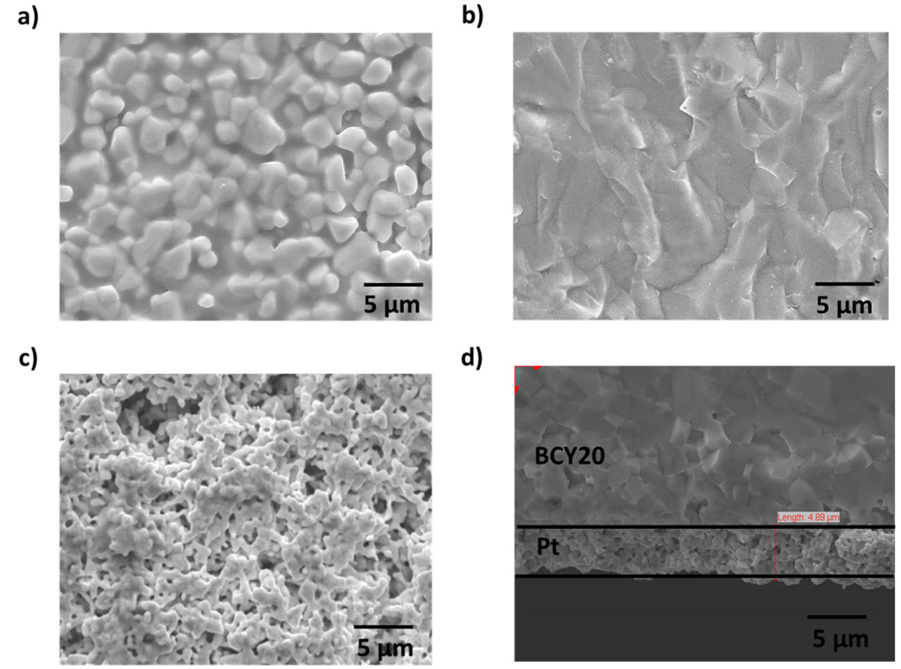
a) The surface of fresh BCY20 membrane, b) cross section SEM image of BCY20, c) The surface image of platinum layer and d) cross section of SEM image of the porous platinum layer. Platinum layer thickness is about 5 μm.
The water permeation of BCY20 membrane modified with different configurations (no platinum, one or both surfaces modified with platinum) were measured. The main purpose was to investigate the impact of surface modification on surface reactions and overall water flux. Under the current experimental conditions, only defect transports are considered. Thus, water permeation process can be described in the following successive steps; water adsorption from the gas phase to the membrane surface (Equation 2), water dissociation (Equation 3), diffusion of protonic defects within the membrane (Equation 4), water recombination (incorporation of hydroxide groups, Equation 5) and desorption of water (Equation 6) from the surface of the membrane.


Water permeation fluxes for different membrane configurations are demonstrated in Fig. 4. Pt|BCY20 presents the membrane configuration where platinum is applied on the feed side of the membrane and the permeate side is left as it is whereas both side modification is shown as Pt|BCY20|Pt. Similarly, permeate side modification is expressed as BCY20|Pt whilst bare membrane is only shown as BCY20. As Fig. 4 indicates that surface kinetics have an impact on overall water flux.
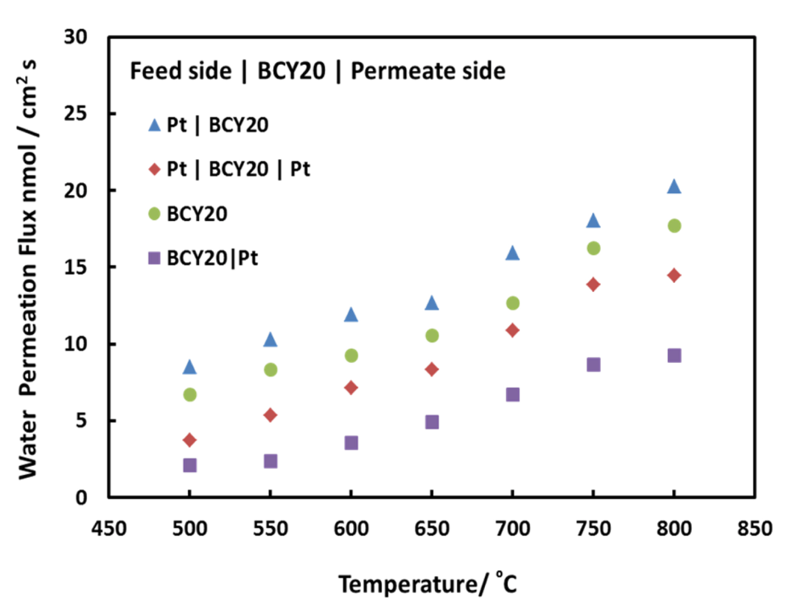
Water permeation fluxes of BCY20 membranes with different configurations between 500°C and 800°C. Feed side; 3% H2O balance with N2, permeate side; dry He.
Examining the impact of platinum on water permeation allows us to understand surface mechanism through the membrane. It can be seen from Fig. 4 that water permeation increases as the temperature rises from 500ºC to 800ºC. This implies that the overall process is thermally activated and temperature has an important role on surface reaction rates or bulk diffusions. Further analysis and discussion will continue at 700ºC since it is an optimum temperature to operate a proton conducting intermediate solid oxide fuel cell and water permeation [21,22].
The water permeation increases slightly when platinum is applied on feed side of the membrane. The water flux is about 13 nmol/cm2s at 700°C for BCY20 and about 17 nmol/cm2s for Pt|BCY20. The surface reaction on feed side consists of multiple steps such as adsorption of water onto the membrane surface, dissociation of water and incorporation of hydroxyl groups and proton into the membrane. These steps have similar effect on permeation. Thus, this suggests that platinum coating on feed side enhances the combined rate of water adsorption, dissociation and incorporation into the membrane.
It has been reported that [23,24] surface coatings such as platinum or silver enhances oxygen exchange kinetics greatly and lowers oxygen dissociation activation energy on its surface compared to bare membrane surface. In addition, platinum is shown to be highly catalytic for protons incorporation into the bulk of Fe-doped SrTiO3 membrane [25,26]. Moreover, the impact of platinum on the surface exchange rate of hydrogen was explored by Hancke et al. Their findings indicated that hydrogen surface exchange energy slightly declined when platinum was coated onto the surface and the authors suggested that either hydrogen dissociation or charge transfer is rate limiting for platinum coated BCY10 surface. Also, water dissociates on Platinum (Pt[110]) surface with an activation energy of 0.44 eV [27] whereas the BCY20 membrane dissociates water on its surface with an activation energy of ~ 0.54 eV [6]. Thus, it may be said that platinum enhances the dissociation and incorporation of water (as hydroxyl groups) into the membrane in this study. Because of that the concentration of hydroxyl groups rises on the feed side, as a result water permeation rate across the membrane increases.
It is reported that migration of protons is faster within the membrane than that of oxygen vacancies [5,13]. As the concentration of hydroxide groups increases on the feed side, protonic defect concentration increases within the membrane and thus, the transport of them increases across the membrane. In order to maintain electro-neutrality condition, the rate of oxygen vacancy transportation may increase which in turn may result in an increase in the rate of water permeation.
On the contrary, Fig. 4 also exhibits that there is a reduction in water permeation when platinum is applied only to both and permeate side of BCY20. The obtained water fluxes are about 7 nmol/cm2s and 11 nmol/cm2s, respectively. This implies that water recombination or water desorption is not catalytically activated by platinum. Water recombination is a different process than water dissociation and may follow a different route. By presuming that platinum surfaces are similar, it can be said that less number of active sites is available for water recombination owing to some site-blocking mechanism in comparison with no platinum surface. Forming one O-H bond requires breaking another O-H bond and during the process proton can switch partner hydroxyl atoms to form water on the permeate side. Therefore, it can be said that water evolution on this surface depends on rapid recombination of protons and oxygen. Moreover, recombination of two hydroxyl groups may result in adsorbed oxygen on the platinum surface. This adsorbed oxygen could restrict other hydroxyl group recombination to form water and as a result decrease water evolution from that surface.
It was previously reported that [28] water desorption from platinum surface does not have simple kinetics, but rather have several paths, including OH recombination and oxygen surface coverage. However, it is not clear which step is the rate determining step. Alternatively there might be the existence of counter reaction which could give the impression of a decrease in water permeation. Instead of water permeation, platinum may catalyse hydrogen evolution from the system  [29].
[29].
Following the water permeation experiments, 1% CO was introduced to the permeate side in order to test the stability of membrane for future use of the membrane in a real fuel cell application with a hydrocarbon fuel. The water-gas shift reaction (CO + H2O ↔ CO2 + H2) is expected to occur with the permeated water on this side. After simultaneous water permeation and water-gas shift experiments, the post operation analysis of the membranes were carried out by XRD, SEM and EDXS in order to determine any possible change in the crystal structure, phase and chemical composition of the membrane. The XRD result of post operation analysis is presented in Fig. 5. All membrane configurations are compared to a fresh BCY20 membrane. Fig. 5b demonstrates the XRD result of feed side BCY20 membrane that is fed with 3% H2O in argon about 45 hours at 700ºC. A decomposition to CeO2 and BaCO3 is observed on this surface which confirms previous reports [30-32]. The following reactions occur in the presence of water on this surface [33];
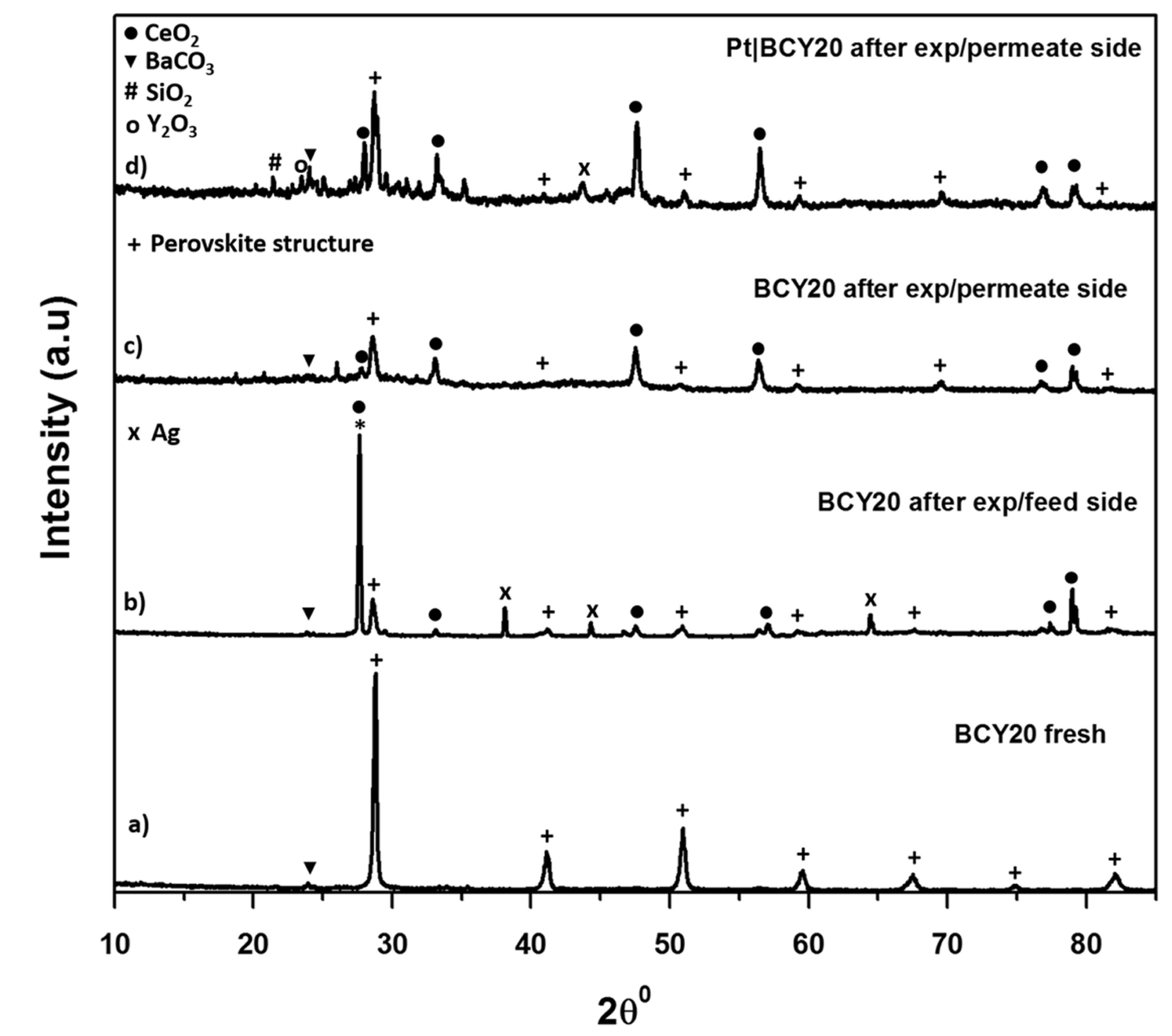
XRD patterns of the fresh and used BCY20 membranes. a) Fresh BCY20 membrane, b) Feed side of the bare BCY20 membrane after the experiment, c) Permeate side of the bare BCY20 membrane after the experiment, d) Permeate side of the “feed_ Pt|BCY20_permeate” membrane after the experiment. The perovskite structure is indicated by +, the peaks indicative of BaCO3, CeO2 and Y2O3 are indicated by ▼,● and o, respectively.


Fig. 5b exhibits no Ba(OH)2 peak owing to a reaction between BCY20 and water in the XRD results which could due to loss of Ba at the surface during sintering or amorphous nature of Ba(OH)2 [34]. The peak at about 26° 2θ may be CeO2 or crystallised silicate.
Fig. 5c and 5d depicts permeate side of BCY20 where 1% CO in helium is fed about 30 hours at 700°C. As can be seen from the figure that BCY20 lost most of its crystal structure and the perovskite structure is disappeared. Both membranes decompose to BaCO3 and CeO2. In addition, multiple minor phases are seen. The presence of SiO2 and Ag might be due to the sealant that is used to seal the membrane to the tube. As the analysis indicates bare BCY20 is unstable under water, CO and CO2 containing atmosphere.
Further analysis is carried on bare and platinum covered surfaces of BCY20 by SEM and EDXS and is presented in Fig. 6. Fig. 6a and 6b shows the feed side surfaces of BCY20. Small particle distribution is seen in Fig. 6a. EDXS measurements depict an approximate atom surface composition of ca 36.3% barium, ca 0.6% cerium and ca 63.1% oxygen on this surface as given in Table 1. From XRD and EDXS result these small particle can be attributed to CeO2. The platinum surface SEM image exhibits a little agglomeration and morphology change underneath, possible due to a reaction between water and barium cerate as shown in Equation 7.

Post operation SEM images of the external surfaces of feed sides (a&b) and permeate sides (c &d). Feed side: a) bare surface b) platinum surface, Permeate side: c) bare surface d) platinum surface.
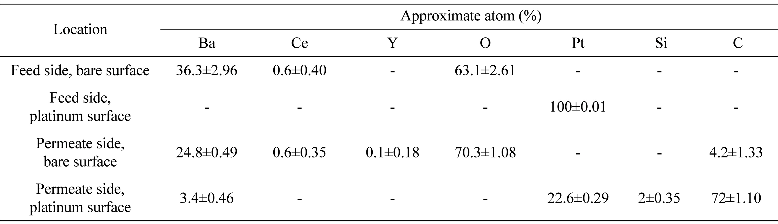
Post operation EDXS average surface compositions of feed sides and permeate sides.
Fig. 6c and 6d exhibit surface images of permeate side of the membrane. A morphology change and distribution of black spots is seen all over the surfaces. Platinum agglomeration is observed in Fig. 6d. The analysis of EDXS in Table 1 shows the presence of carbon on both surfaces with higher content on the platinum surface. This indicates that carbon accumulation is high on the platinum surface possible due to carbon monoxide disproportionation. Additionally, carbon monoxide has the ability to bind on platinum active sites even at low ppm levels [35, 36]. Carbon monoxide can also react with the surface lattice oxygen and could cause a surface morphology change as in Fig. 6c [37].
4. Conclusions
BCY20 membranes were used with different modifications for water permeation. The results demonstrated that water permeation can be increased by application of platinum on the feed side, indicating that platinum has a catalytic effect on water dissociation/incorporation. However, a decrease in water flux is observed when platinum is applied on the permeate side, suggesting that platinum on that side has a negative role in water recombination. Platinum seems to block water recombination mechanism which could be owing to a reduction in the active sites for water recombination or low ionic conductivity of platinum. In addition, the stability experiments revealed that the presence of platinum on the permeate side is detrimental for both water permeation and carbon deposition.
Acknowledgements
The authors would like to acknowledge the Ministry of National Education Turkey for funding. Also, we would like to thank Prof Ian Metcalfe for the useful discussions and School of Chemical Engineering, Newcastle University, UK for the university’s resources.