Characterization of Electric Double-Layer Capacitor with 0.75M NaI and 0.5 M VOSO4 Electrolyte
Article information
Abstract
We describe a redox-enhanced electric double-layer capacitor (EDLC) that turns the electrolyte in a conventional EDLC into an integral, active component for charge storage—charge is stored both through faradaic reactions with soluble redox-active molecules in the electrolyte, and through the double-layer capacitance in a porous carbon electrode. The mixed-redox electrolyte, composed of vanadium and iodides, was employed to achieve high power density. The electrochemical reaction in a supercapacitor with vanadium and iodide was studied to estimate the charge capacity and energy density of the redox supercapacitor. A redox supercapacitor with a mixed electrolyte composed of 0.75 M NaI and 0.5 M VOSO4 was fabricated and studied. When charged to a potential of 1 V, faradaic charging processes were observed, in addition to the capacitive processes that increased the energy storage capabilities of the supercapacitor. The redox supercapacitor achieved a specific capacity of 13.44 mAh/g and an energy density of 3.81 Wh/kg in a simple Swagelok cell. A control EDLC with 1 M H2SO4 yielded 7.43 mAh/g and 2.85 Wh/kg. However, the relatively fast self-discharge in the redox-EDLC may be due to the shuttling of the redox couple between the polarized carbon electrodes.
1. Introduction
The addition of redox-active ions to electrolytes is a recent strategy for enhancing the energy density of electric double-layer capacitors (EDLCs) by extending electrode/electrolyte interface-limited charging sites into the electrolyte matrix [1-5]. Typical EDLCs provide superior power and long-term stability compared with batteries, because their charging mechanisms are based on physical-ion adsorption. However, the low-to-moderate volumetric and gravimetric energy densities of EDLCs limit their widespread application [6,7]. To expand the commercial applications of conventional EDLCs, for example in hybrid automobiles, the specific energy capacity must be increased. The lower energy capacity of EDLCs is mostly attributed to intrinsically surface-limited charging processes, such that the electrolyte ions electrostatically adsorb onto the electrode surface exposed to the electrolyte. In EDLCs with redox-active ions, the added redox-active species go through oxidation/reduction (redox processes) at the operating voltages while utilizing the electrostatic adsorption. In other words, the redox-active solution expands the electric charge capacity through the additional faradaic charging in combination with the capacitive charging based on the physical-ion adsorption.
Our goal is to turn the electrolyte component in a conventional EDLC into an integral and active electrochemical energy storage component by harnessing the faradaic reactions of redox-active additives in the electrolyte. In recent years, several studies have sought to explore this additional charge storage mechanism from the dissolved redox-active ions in solution. Alkali ions, vanadium ions, indigo carmine, and quinone group compounds were employed as soluble redox-active species in the electrolyte [1-5,8]. This dissolved species redox process possibly provides faster reaction kinetics compared with a pseudocapacitor, based on the electrode-confined faradaic reaction from the solid transitional metal or two-dimensional material [9,10]. The dissolved redox-active ions in the electrolyte raise the capacitance of EDLCs through additional faradaic reactions, as well as double-layer charging at one electrode. This increased capacity is not optimized from the perspective of a cell, because the obtainable capacity relies on the presence of lower-capacitance electrodes in the complete cell [11]. Therefore, full cell capacity would be severely impaired by the capacitance of an electrode showing capacitive charging. To take full advantage of the higher faradaic changing capacity at one electrode, the introduction of a counterpart redox couple was aimed at the other electrode. In other words, the development of a redox-enhanced EDLC based on the coupling of two redox species is the main goal of this work.
To reinforce the practical merits of designing redox-enhanced EDLCs, we used an economical aqueous-based electrolyte rather than a high-cost organic solution or ionic liquid. Water-based electrolytes can be readily prepared by dissolving low-cost salts into water in ambient air, without the need for any complex procedures [12,13]. In addition, the high ionic conductivity of aqueous electrolytes can increase the specific power of an energy device based on reduced internal resistance. This can also allow a cell to have a thicker electrode, resulting in an increased ratio of active materials to the accessory component [14]. These benefits might allow aqueous-EDLCs to become commercially competitive [14]. Furthermore, water-based electrolytes do not pose the same safety risks as those associated with flammable organic solvents. However, the narrower operable potential of aqueous systems would significantly lower the achievable energy of EDLCs, because of the square dependence of the stored voltage energy [12]. The additional faradaic charging by redox-active ions makes the aqueous-based system more practical, by compensating for the reduced achievable energy of the water solvent.
Given our primary objective of designing a high-energy aqueous supercapacitor, we have screened a variety of soluble redox-active species as conjugate pairs for energy storage in redox-EDLCs. In particular, the redox-active species that oxidize/reduce within the stable potential of water were regarded as candidates to prevent energy loss by the electrolysis of aqueous electrolytes. The redox electrolytes were assembled with practical carbon electrodes into a full cell, which was then electrochemically tested to study its charge storage reactions and accompanying self-discharge. We evaluated the specific capacity and energy density achievable by the redox-enhanced EDLC, as well as other performance parameters, such as coulombic and energy efficiency.
2. Experimental
2.1. Synthesis of CO2-activated carbon
The CO2-activated carbon used as the electrode material of the redox supercapacitor was manufactured by activating the CO2 on the carbon precursor (Donacarbo, Osaka Gas Co., Ltd.). Approximately 1 g of carbon precursor was positioned in a tube furnace, and was activated at 890 ℃ under 100 mL min-1 of flowing CO2 for 22.5 h, with heating and cooling ramp rates of 5 ℃ min-1. The burn-off of the sample was estimated at 70.97 % based on the reduced mass.
2.2. Electrode preparation
The electrodes for the redox supercapacitor were fabricated by mixing the CO2-activated carbon, binder, and conducting additive in an 85:10:5 mass ratio. Polytetrafluoroethylene (PTFE) and acetylene black were employed as the binder and conducting additive, respectively. The mixture compound was pressed into a pellet by a pellet die under 2000 psi. Fabricated self-standing pellets of approximately 10 mg were used as the electrodes in the supercapacitor device. A stainless-steel bar was employed as the current collector.
2.3. Electrolyte preparation
The electrolyte solutions were prepared by dissolving the salts (including the redox-reactive ions or electrochemically inert ions) in deionized ultrapure water (18.2 MΩ). The salts used for solution preparation were purchased as follows: sodium iodide (KI, 99 %, Alfa Aesar), potassium bromide (KBr, 99.999 %, Alfa Aesar), and sulfuric acid (Showa).
2.4. Electrochemical characterization
For the electrochemical measurement of a supercapacitor composed of electrode pellets and redox electrolytes, a tee-type Swagelok device was used to configure the three-electrode cell. Two identical carbon pellets made with CO2 activated carbon were separated by Whatman filter paper in the Swagelok device, and both electrodes were pushed by the stainless-steel bar. The variation of the independent potential at the positive and negative electrodes was monitored versus a reference saturated calomel electrode (SCE, Hg/Hg2Cl2) during the measurement. Self-discharge in the redox supercapacitor was tested not only by monitoring the potential change at an open circuit, but also by estimating the remaining capacity. Prior to measuring the self-discharge, the cell was charged by applying a constant current to the appropriate potential. Subsequently, the cell remained in an open-circuit condition, monitoring the potential change for different amounts of time, followed by discharging with a constant current to 0 V. The preserved capacity in the cell was indirectly calculated from the discharge capacity. All electrochemical tests were performed using a potentiostat/galvanostat (SP-200, Bio-Logic).
To take advantage of the redox reactions of the aqueous electrolytes, the redox potential of the redox couples must be in the stable potential range of the water. Because of the large overpotential of carbon electrodes, the redox reaction could occur at a redox couple outside the water-stable window without water decomposition.
3. Results and Discussion
Iodide (I-/I3-) was investigated as a candidate redox couple for positive electrodes by galvanostatic cycling because the redox potential of iodide falls within a water-stable range. Fig. 1 (a) shows a galvanostatic charge/discharge graph for a 0.75 M KI solution. A flat potential curve is observed on the positive electrode (orange line). This potential profile at the positive electrode is assumed to be the redox reaction between I-/I3-, based on the Pourbaix iodide diagram shown in Fig. 5 (b). In contrast, the potential profile at the negative electrode (blue line) linearly decreased/increased when a charging/discharging current was applied, respectively. The linearly dependent potential curve of the applied current indicates the capacitive charging of K+ ions on the negative electrode. The charge/discharge cycle in a KI solution has a coulombic efficiency of 99 %. The high coulombic efficiency of this electrochemical cell (close to 100 %) indicates that only the redox reaction of the iodide redox couple occurs in the redox electrolyte, including an iodide couple without water decomposition. Thus, the iodide electrolyte could be used as the redox couples for the successful development of a positive electrode.
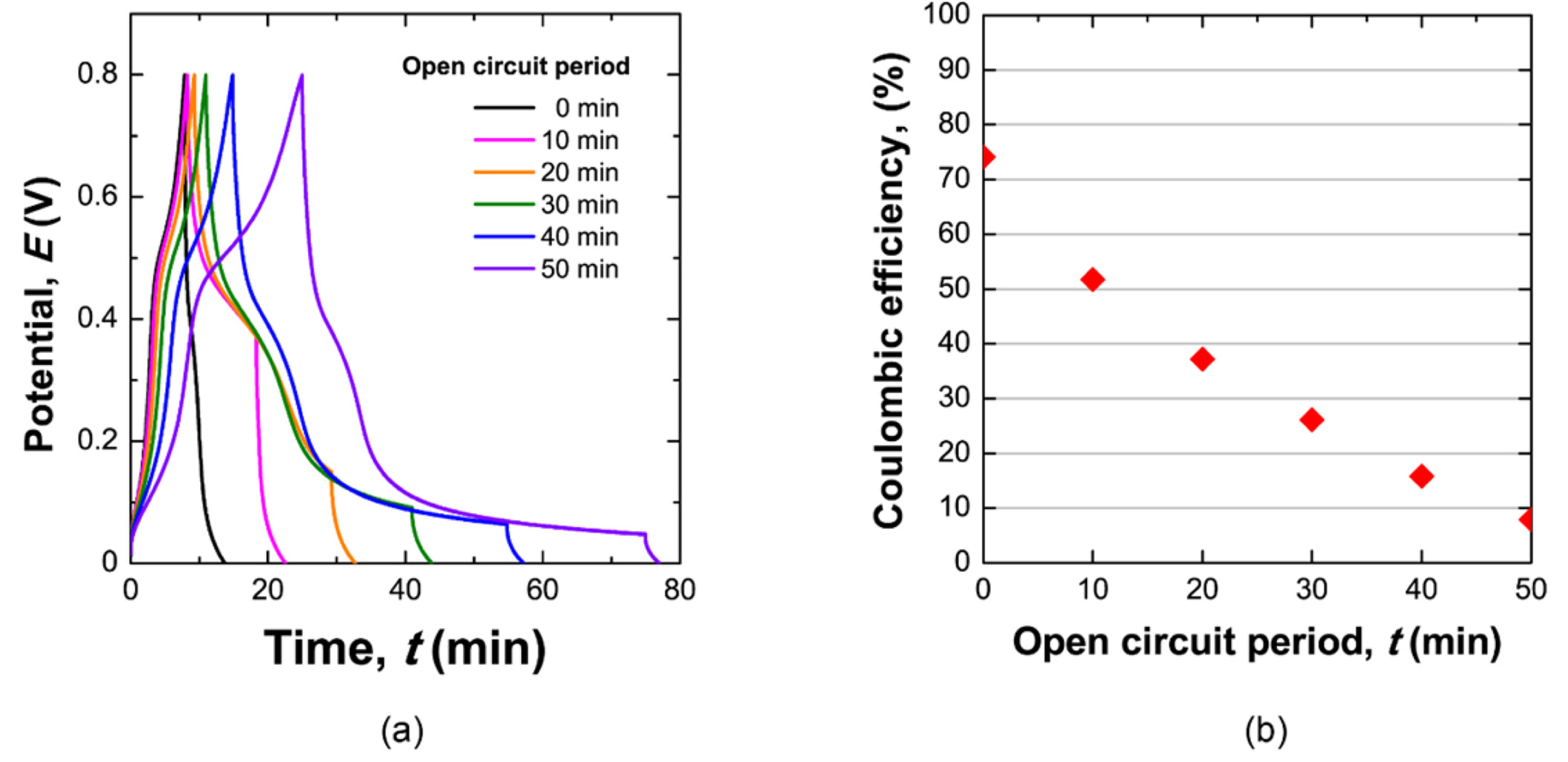
(a) The potential profile of a cell containing a 0.75 M NaI and 0.5 M VOSO4 electrolyte during the self-discharge experiment. After charging to 0.8 V with a constant applied current, the cell remained in an open circuit for different amounts of time. After the open circuit period, the cell was discharged by applying a constant negative current. (b) Corresponding results for the conserved capacity as a function of open circuit time.
Self-discharge should be considered as a critical parameter of a candidate redox electrolyte because a cell with rapid self-discharge cannot play the role of an energy storage device. Self-discharge was measured by a galvanostatic charging/discharging test, as described in the Experimental Methods section. The experimental result for the self-discharge of the KI solution is shown in Fig. 1 (a), and the charge loss in the open circuit is shown in Fig. 1 (b). According to the self-discharge test, 96 % of the stored charge remained after 10 min of self-discharge. In a redox supercapacitor with KI solution, the self-discharge rate is comparable to that of an EDLC.
The redox reactions in a VOSO4-only solution were studied using galvanostatic cycling, with the results shown in Fig. 3. The supercapacitor was initially charged with a constant current of 1 A g-1 (black trace line). However, the cell potential can never reach the maximum set potential of 1 V. While applying a constant current of 1 A g-1, a potential plateau was observed near 0.80 V (vs. NHE) and 0.12 V (vs. NHE) for the positive and negative electrode, respectively. Comparing the potential plateau at each electrode with the Pourbaix diagram of vanadium, these two potential plateaus correspond to redox potentials of VO2+/VO2+ and VO2+/V3+ at the positive and negative electrode, respectively. Therefore, the reason that the cell does not reach its maximum potential under 1 A g-1 charging is thought to be the fast self-discharge by the redox reaction between the oxidized VO2+ and reduced V3+ from VO2+. When the applied current is increased to 2 A g-1, the maximum potential (1 V) can be reached, with a coulombic efficiency of 22.39 %, which is quite low. This low efficiency can be attributed to the redox reaction between the oxidized and reduced species from VO2+. In other words, when the oxidized and reduced species are simultaneously evolved, and meet each other in a solution, rapid self-discharge is induced by the electron exchange between the two species.
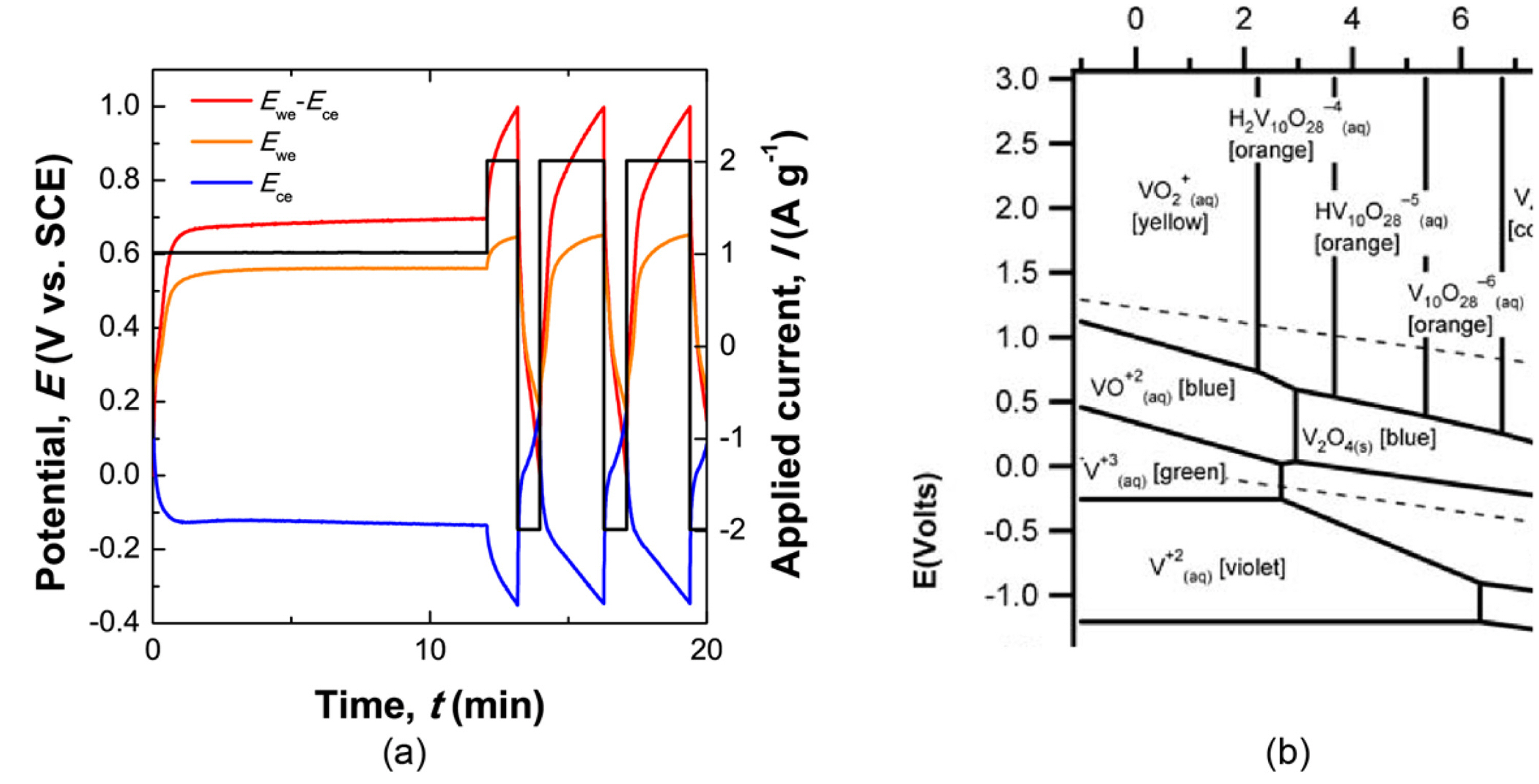
(a) Galvanostatic charge/discharge cycling in a 0.5 M VOSO4 solution, and (b) Pourbaix diagram of vanadium.
(a) Self-discharge test in 0.75 M KI solution, and (b) corresponding results of the preserved capacity as a function of the open circuit period.
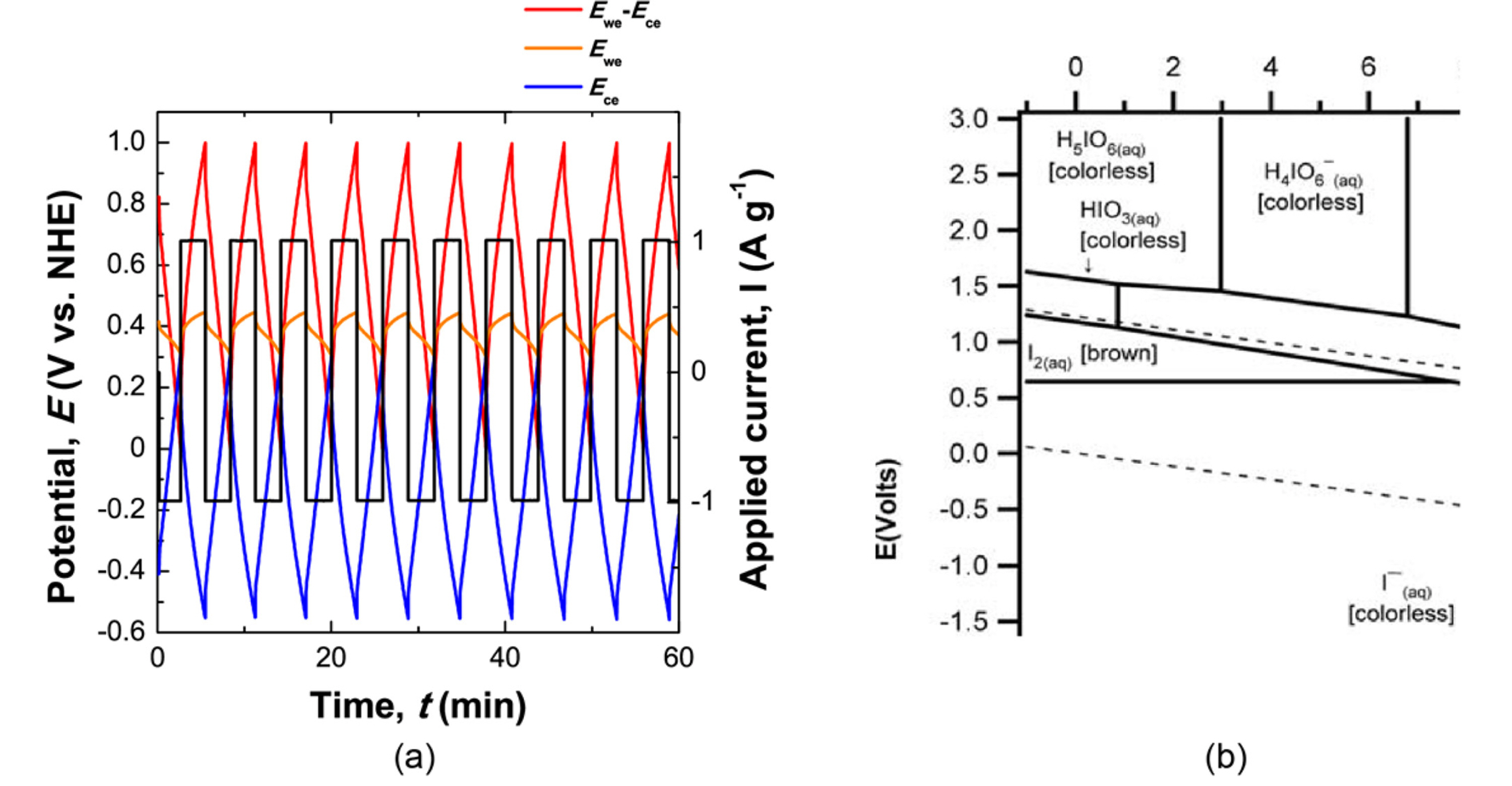
Since our main goal is to fabricate electric double-layer capacitors based on two redox couples, we assembled a cell with redox couples of both iodide and vanadium ions. Charge capacity and self-discharge were measured for this assembled redox cell. We analyzed the electrochemical reactions in this supercapacitor, which had a 0.75 M NaI and 0.5 M VOSO4 solution, during cell charging/discharging under a constant applied current (galvanostatic cycling). Fig. 5 (a) shows the potential profile of each electrode in response to an applied current of 1 A g-1 during galvanostatic cycling. As a control parameter, the applied current is colored in black. The response potentials at positive and negative electrodes are represented by orange and blue-colored lines, respectively. The coulombic efficiency (discharge capacity/charge capacity) is calculated to be 57.53 %.

Galvanostatic cycling graph measured on a redox supercapacitor with a 0.75 M NaI and 0.5 M VOSO4 solution of pH 1.76. The potential change at each electrode was monitored in response to a constant applied current. The red, orange, and blue trace lines correspond to the full cell potential (Ewe–Ece), the positive electrode potential (Ewe), and the negative electrode potential (Ece), respectively. Pourbaix diagrams of iodide and vanadium are presented in the right column for comparison.
We investigated the redox reactions occurring in an electrolyte with two different redox couples by comparing the response potentials and Pourbaix diagrams of two redox species. For a fully discharged cell (0 V at the red-colored cell potential), the potentials of both electrodes remained at 0.44 V (vs. NHE). During charging/discharging, the potential at the positive electrode swung between 0.44 V (vs. NHE) and 0.53 V (vs. NHE), and the potential at the negative electrode oscillated between 0.44 V (vs. NHE) and −0.47 V (vs. NHE). Potential plateaus were observed for the electrodes near 0.49 V (vs. NHE) and 0.04 V (vs. NHE). These values are comparable to the redox potentials of I-/I3- and of V3+/VO2+ at pH 1.76 in the Pourbaix diagrams of iodide and vanadium, respectively. In practice, because the mixed solutions could have various complex compositions of iodide and vanadium, the possible redox reactions in actual cells are not as simple as those suggested here. This is a first-order estimation of a primary redox reaction in a redox supercapacitor.
The discharge capacity of this redox supercapacitor was tested to explore the self-discharge rate and mechanisms of a supercapacitor using two redox electrolytes. For the self-discharge test, the cell was previously charged to a cell potential of 0.8 V by applying a positive constant current. The cell remained under an open circuit condition for various amounts of time, and then discharged to a cell potential of 0 V with an applied negative constant current. The reduced capacity of an open circuit can be considered to be the capacity loss due to self-discharge, and is indirectly calculated based on the capacity measured during discharging (discharge capacity). The capacity remaining after self-discharge was plotted as a function of the open circuit period, as shown in Fig. 5 (b). Only approximately 10 % of the charged capacity was conserved after 50 min of self-discharge. The rapid self-discharge rate in mixed solutions of 0.75 M NaI and 0.5 M VOSO4 is presumably related to the quite low coulombic efficiency of 57.53 %. During charging, the oxidized I3- from I- and reduced V3+ from VO2+ could diffuse away from the electrode, and electrons could be exchanged in the solution. This charge transfer between two different redox species would contribute to the low coulombic efficiency and fast self-discharge rate.
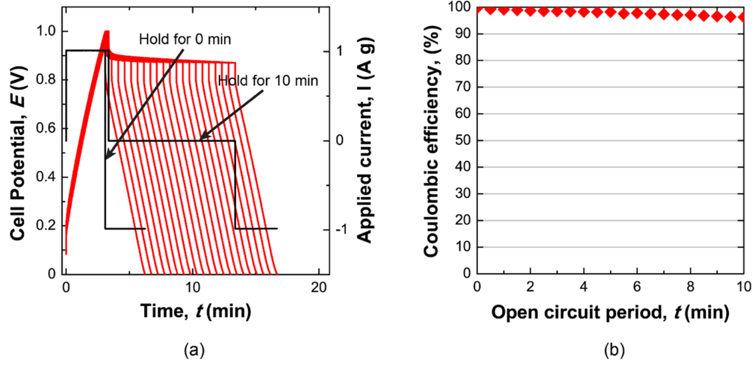
As a reference for the self-discharge rate in the redox supercapacitor, the self-discharge of an EDLC was measured in a 1 M H2SO4 solution. The self-discharge of the EDLC was estimated by the same procedure used to measure the self-discharge of the redox supercapacitor. During charging, H+ and SO42- ions can introduce electric double layers in the negative and positive electrode, respectively. Fig. 6 (a) shows the cell potential profile during the self-discharge experiment, and Fig. 6 (b) shows the conserved capacity after self-discharge. The EDLC cell has a significantly slower self-discharge rate than the redox supercapacitor with the NaI and VOSO4 solution.

(a) Graph of the potential change monitored during a sequence of charging, self-discharge, and discharging. (b) Corresponding conserved capacity as a function of the open circuit period.
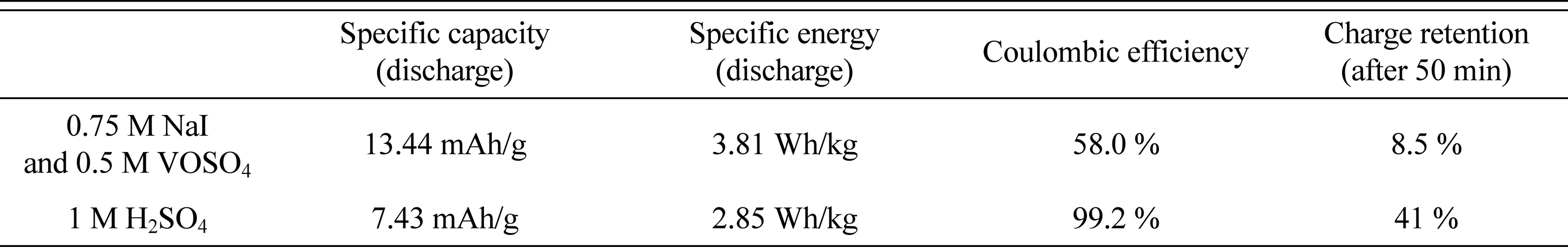
Performance metrics obtained from the cells with 0.75 M NaI and 0.5 M VOSO4 solutions and 1 M H2SO4 solution.
The redox supercapacitor with mixed NaI and VOSO4 electrolytes exhibits a higher specific capacity and energy density, based on the faradaic charging process of the iodide and vanadium ions. However, the lower charge retention and coulombic efficiency of the 0.75 M NaI/0.5 M VOSO4 solution (relative to a 1 M H2SO4 solution) can be attributed to the faster self-discharge of the redox ions (iodide and vanadium ion). The self-discharge mechanism in the redox supercapacitor has not yet been clarified by these electrochemical tests. A redox-enhanced EDLC using 0.75 M NaI and 0.5 M VOSO4 can only perform short-term energy storage. To mitigate self-discharge in redox electrolyte-based supercapacitors, a fundamental understanding of self-discharge mechanisms is required. Further research on such electrochemical reactions should be conducted.
4. Conclusions
We designed a redox-enhanced EDLC based on an iodide and vanadium redox couple to boost the charge capacity and energy density of a traditional EDLC. The specific capacity and energy density of a cell with 0.75 M NaI/0.5 M VOSO4 were measured as 13.44 mAh/g and 3.81 Wh/kg, respectively. These values indicate higher performance than that for a 1 M H2SO4 EDLC cell. The rapid self-discharge could occur because of the shuttling of redox ions between electrodes. We estimated the charge retention to calculate the self-discharge rate after charging the assembled cells. The redox-EDLC lost 91.5 % of its charged capacity during an open circuit period of 50 min, which is much faster than the self-discharge rate of an EDLC (59 % charge loss of the initial charge). For the redox-EDLC to be used as an energy device, further study on the self-discharge mechanism should be conducted.
Acknowledgements
This work was supported by the National Research Foundation of Korea (NRF) grant funded by the Korean government (Ministry of Science and ICT) (No.2017R1C1B2005470).