1. Introduction
A consensus has been reached among most countries worldwide regarding the need to replace fossil fuels with renewable energy sources, with the majority of countries committed to becoming carbon-neutral. Electric vehicles (EVs) are key to a paradigm shift that can dramatically reduce greenhouse gas emissions, such as CO2 [1ŌĆō4]. EVs use electric motors rather than fossil fuels, and Li-ion batteries (LIB) are their major power source. LIBs have revolutionized modern society over the past decade by powering portable devices such as cell phones and laptops [5ŌĆō7]. A surge in the supply of LIBs has driven prices down over the last decade, making EVs economically viable [8ŌĆō11]. However, despite the mass adoption of LIBs in EVs, some consumers still worry about an insufficient driving range, which is highly dependent on the energy density of the battery [12ŌĆō17]. Therefore, a further increase in the energy density of LIBs is urgently required.
Optimizing cell engineering is a straightforward approach to increasing the energy density of battery packs. In particular, a high loading level (thick electrode) is essential during electrode fabrication to meet the high energy density demands of LIBs [18]. However, the development of cell configurations at high loading levels is limited because the internal resistance drastically increases with increasing electrode thickness upon cycling. Internal resistance generally includes ionic and electronic resistances, and numerous studies have recently reported that these two resistances are more dominant in terms of cell degradation in thick electrodes. Lee et al. reported electrochemical reaction heterogeneity in a thick LiNi0.6Co0.2Mn0.2O2 electrode after long-term cycling with three stacked electrodes [19]. The uneven Li-ion distribution in the electrode thickness direction due to pore clogging from the top implies that the deterioration of Li-ion conduction is more dominant than that of electronic conduction during cell failure.
In light of the above, Ni-rich layered oxides, such as LiNixCoyMn1ŌłÆxŌłÆyO2 (NCM) and LiNixCoyAl1ŌłÆxŌłÆyO2 (NCA) with greater than 80% Ni content, may suffer from more severe capacity fading because of the intrinsically low mechanical strength compared to LiNi0.6Co0.2Mn0.2O2 [20]. Ni-rich NCM and NCA undergo several phase transitions from the hexagonal phase to the monoclinic phase, to the H2 phase, and finally to the H3 phase. This crystal structural transformation is accompanied by the microcracking of particles owing to the anisotropic volume change during charging [21,22]. The active particles at the top of the thick electrode experiences a wider change in state of charge (SOC) than that at the bottom. Therefore, the particles at the top of the electrode are cracked earlier than the particle at the bottom during cycling, leading to blocking the pores in the electrode and increasing the resistance against Li-ion diffusion in the pore network of electrode [23,24]. Hence, a new thick electrode design should be proposed to achieve a high energy density of LIBs while considering the mechanical fragility of the cathode materials according to the SOC.
Herein, we provide new insights into the design of thick Ni-rich layered oxide electrodes via multilayer coating between the LiFePO4 (LFP) (top) and LiNi0.8Co0.1Mn0.1O2 (NCM811) (bottom) to mitigate microcrack issues at the top of the electrode. The outstanding electrochemical, structural, and mechanical stabilities of LFP are beneficial for mitigating microcracks and further electrolyte decomposition on top of thick electrode configurations, even with uneven SOC, resulting in a significantly improved cycling performance of thick electrodes. Furthermore, ex-situ analyses, including scanning electron microscopy (SEM) with energy dispersive X-ray spectroscopy EDX and X-ray diffraction (XRD) of the electrode after long-term cycling at a high current rate of 1 or 2 C, were conducted to thoroughly investigate the mitigation of microcracks and uneven SOC distribution. We expect that the new design strategy presented herein will help mitigate the inherent challenges of a thick electrode configuration.
2. Expermental
2.1 Preparation of single-layer electrodes
NCM811 and LiFePO4 cathode materials were purchased from the MTI Corporation and used without further processing. The cathode electrode was prepared by mixing the electrode material (NCM811 or LFP), Super-P (TIMCAL), and PVDF (Solvay) at a mass ratio of 90:5:5 in NMP (99%, Sigma-Aldrich) solvent. The slurry was thoroughly mixed at 1,000 rpm for 1 h using a paste mixer (Han-tech) to obtain a homogeneous mixture. The slurry was then cast onto an Al current collector. All electrodes were dried at 120C in a vacuum oven overnight. The total thickness of electrode was fixed by 55 ╬╝m including Al of 20 ╬╝m. The areal capacities of all electrodes are 1.0ŌĆō1.2 mAh cmŌłÆ2. Note that the areal capacity and mass loading of each electrode was set arbitrarily to make the electrode thickness 35 ╬╝m.
2.2 Preparation of multilayer electrodes
A slurry of the cathode materials for the top layer was prepared in the same manner as that for the single-layer electrodes. First, the slurry was cast onto an as-prepared single-layer electrode, and then the electrodes were dried at 120C in a vacuum oven overnight. The thickness of the NCM811 layer was 25 ╬╝m and LFP was 15 ╬╝m. The difference is to achieve moderate energy density. The electrodes were rollpressed after each casting the bottom and top layer.
2.3 Electrochemical analyses
Coin type 2032 half cells were fabricated by pairing each cathode electrode with a Li metal anode as the reference and counter electrodes in a dry room where the dew point was controlled to be under ŌłÆ60┬░C. The electrolyte used was 1 M LiPF6 in EC/EMC at a volume ratio of 3:7 (Panaxetec). All the cells were cycled at a C/10 rate for the initial cycle, followed by 200 or 100 cycles at a 1 or 2 C rate between 3.0 and 4.3 V (vs. Li/Li+), respectively. The rate performances of the electrodes were also compared at various current densities (C/10 to 20 C).
2.4 Characterization
Powder XRD patterns were collected with Cu K╬▒ radiation (╬╗ = 1.54184 ├ģ) over a 2╬Ė range of 10ŌĆō80┬░ with an Empyrean instrument (PANanalytical). The morphology and microstructure of the cross-sectioned electrode after 100 cycles were examined using SEM and EDX. Inductively coupled plasma mass spectroscopy (ICP-MS) was also performed to determine the content of each cathode material between NCM811 and LFP in the multilayer electrode. The uncycled electrode was scraped, dissolved in an acidic solution, and filtered to eliminate the contributions of carbon and other substances.
3. Results and Discussion
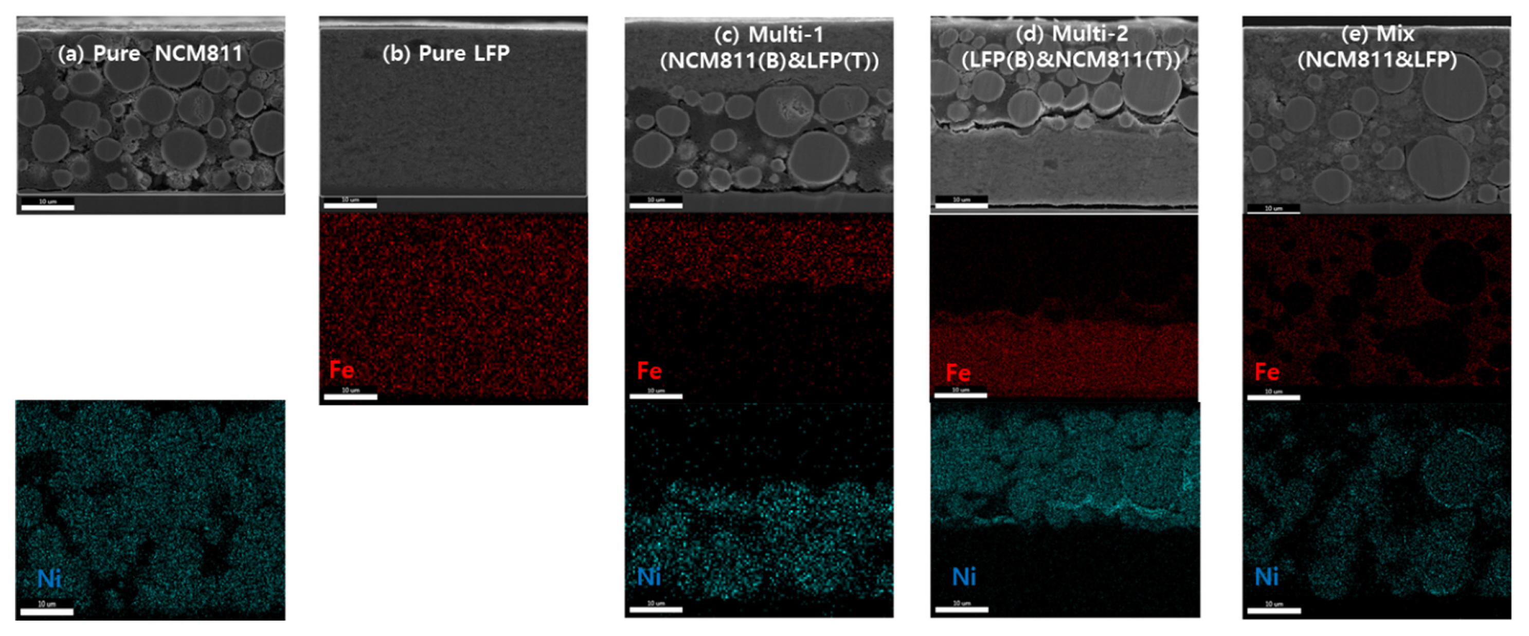
For electrochemical performance comparison, five types of electrodes were created: three single-layered electrodes and two multilayered electrodes. The cross-sectional SEM and EDX images confirmed the layered structure of the prepared electrodes (Fig. 1). The LFP and NCM811 layers can be clearly distinguished in the SEM images because of their particle sizes, and EDX mapping further confirmed the elemental identification of each layer (Fig. 1a,b). For SEM, the Ni in the NCM811 particles and the Fe in the LFP particles could be distinguished using EDX-mapping images of Ni and Fe. The Multi-1 and Multi-2 electrodes in Fig. 1c,d are both composed of LFP and NCM811 in a 31:69 weight ratio but are casted by different orders. The compositions of LFP and NCM811 of multi electrodes were determined from the Fe and Ni concentrations determined using ICP-MS. Based on the ICP-MS values, the transition metals Ni and Fe concentrations were converted to the total masses of NCM811 and LFP, respectively. LFP and NCM811 powders in the mixed electrode were homogeneously mixed in the same ratio as the ICP values of Multi-1 and Multi-2. The thicknesses and compositions of the Multi-1, Multi-2, and mixed electrodes were the same. Similarly, the mixed electrode was also prepared (Fig. 1d).
The active materials at different positions on the electrode exhibited different polarization behaviors. The voltage curves of the four cell types during the 1st cycle are shown in Fig. 2a. The voltage curves of the NCM811 and LFP cells with a single type of active material demonstrated voltage plateaus of 3.8 and 3.5 V vs. Li/Li+, respectively. These two types of active materials exhibited clearly distinguishable voltage curves. The voltage plateaus of the single-type electrodes were highly consistent with those in previous reports [25ŌĆō27]. Fig. 2b depicts the cyclability of the electrodes. The specific capacity of the NCM811 electrode was 180 mAh gŌłÆ1 for the first cycle and gradually declined with subsequent cycles (black dots in Fig. 2b). The capacity faded rapidly from 130 mAh gŌłÆ1 for the 80th cycle to 20 mAh gŌłÆ1 for the 170th cycle. The failure during prolonged cycling can be attributed primarily to particle microcracks and electrolyte decomposition, as reported in the literature [21,28]. The failure mechanism is discussed in comparison with other electrodes in the following discussion. By contrast, both the Multi-1 and Multi-2 electrodes exhibited improved cyclability, with cycle retentions of 68% and 50% compared to that of 11% for NMC811. The LFP electrode displayed a better cycle life than the NCM811 electrode. LFP ensures a high cycle life with a low operating potential and a stable crystalline structure. Interestingly, the Multi-2 electrode lost 40% of its capacity during the initial 60 cycles, and then, the capacity stabilized with a moderate capacity decrease for the remaining cycles. In contrast, the capacity of the Multi-1 electrode decreased linearly over 200 cycles. The different capacity fading behaviors are apparent in the voltage profiles shown in Fig. 2c,d. The voltage profile of the Multi-1 electrode in Fig. 2c shows that both LFP and NCM811 contributed to the total capacity, although their capacities gradually decreased during cycling. However, the voltage profile of the Multi-2 electrode in Fig. 2d indicates that the discharge plateau of LFP at ~3.4 V was significantly shortened and polarized during initial cycling. After the 50th cycle, the LFP layer of the Multi-2 electrode was not lithiated during the discharging period and thus became almost inactive in the subsequent cycles. In other words, after the 50th cycle, the LFP layer does not participate in the electrochemical reaction. A reasonable explanation is that electrolyte decomposition or particle cracking occur on top of NCM811, and the decomposition products or cracked particles hinder ion transportation in the pores, leading to a capacity loss in the bottom layer. Subsequently, only the NCM811 layer delivered a capacity of approximately 80 mAh/g. In contrast, the increase in resistance in the Multi-1 electrode was not significant, as shown in Fig. 2c, which is likely attributed to the LFP contained in the upper layer had good structural safety and interfacial stability. The mixed electrode contained NCM and LFP powders in the same ratio as in the Multi-1 and Multi-2 electrodes, and its performance was comparable to that of the pure NCM811 electrode. Consequently, the cyclability characteristics of the mixed electrode, in which NCM and LFP were scattered without a defined location, were between the performances of the Multi-1 and Multi-2 electrodes.
Cracking of the NCM811 particles after prolonged cycling are observed in the SEM images shown in Fig. 3. The particles at the top of the NCM811 electrode (Fig. 3a) were broken down into small particulates after cycling, whereas the bottommost particles were relatively stable (Fig. 3b). The inhomogeneity in the electrode implies that the active particles at the top experienced a more severe volume change and mechanical stress than those at the bottom. At the top of the electrode, Li+ diffusion is straightforward during Li insertion/desorption because the top of the electrode is in contact with the electrolyte, which enables the supply and dissolution of large amounts of Li ions. However, the ion diffusion from the electrolyte side to the current-collector side is relatively convoluted due to the porous electrode layer. This problem is minor indeed under a low-current operation; however, a high-current density operation leads to a significant gradient in the concentration of Li+, thus concentration polarization. The relatively small concentration polarization at the top of the electrode allows a locally high current density on the top of the electrode layer, such that the top layer is locally overcharged and discharged compared to the bottom layer. The isolated particles will likely be electronically inactive and block the pores, impeding ion diffusion. In contrast, the particles in the Multi-1 electrode remained stable for 200 cycles (Fig. 3c). The LFP layer in the Multi-1 electrode remains stable even under a local high current because of its structural stability and marginal volume change. The particles at the top of the Multi-2 electrode were broken during cycling, which again indicates that the top region of the electrode is in an electrochemically stressful environment, leading to mechanical degradation of the NCM and electrolyte oxidation (Fig. 3d).
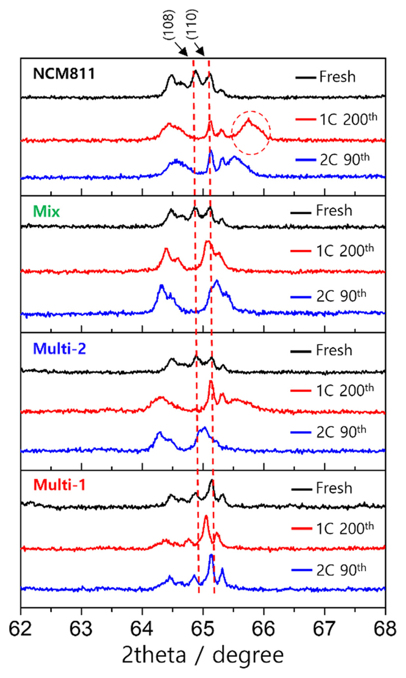
XRD measurements were performed to confirm the SOC of the cycled electrodes, as shown in Fig. 4. The electrodes were collected in the discharged state. After 200 cycles, the NCM811 electrode showed an additional peak at 66┬░, which is the characteristic peak of delithiated NCM811. The XRD pattern confirmed the presence of lithiated and delithiated particles in the discharged electrode, consistent with the failure of NCM811 and Multi-2, shown in the SEM images in Fig. 3. The XRD pattern obtained from the Multi-1 electrode shows that the inhomogeneity was significantly suppressed.
4. Conclusions
High-loading electrodes with minimal amounts of inactive components are highly desirable for advanced LIBs with high energy densities. However, the electrochemical uniformity of thick electrodes degrades during cycling because of the loss of electronic or ionic conductivity. In this work, a laminated cathode was proposed to overcome ionic conductivity loss. The multilayered cathode with an LFP top layer and NCM811 bottom layer exhibited superior cycle retention compared to the pure NCM811 and LFP electrodes. The superior cycle retention can be attributed to the structural and interfacial stability of LFP at the top of the thick electrode, which is in an electrochemically harsh environment. This work provides a meaningful strategy for fabricating LIBs with a high energy density for various applications.