


1. Introduction
Flexible energy sources are gaining much attention owing to their potential use in flexible electronic devices such as flexible displays, wearable electronics, and so on. Because the flexible device approach increases the degree of freedom for various applications, it will show continuous growth and research focus. Although it is in its earliest stages of development, a number of reviews on flexible lithium ion battery (LIB) systems have been reported in the last two years [1-4]. Most reviews focus on the introduction of studies made for LIB systems. In addition to overcoming difficulties associated with flexibility, state-of-the-art flexible LIBs also have to deal with the challenging issues faced by conventional LIBs such as obtaining a high energy density, an improved rate capability, and new materials development.
A LIB cell is composed of two electrodes, which are the anode and cathode, a separator, and an electrolyte. Generally, the electrodes are fabricated by applying coating slurry onto a metallic foil (copper and aluminum). The coating slurry contains an organic solvent, active materials, conducting particles, and binders. Polyolefin-based porous membranes, which are flexible films, are used as separators. Carbonate-based liquid containing lithium salt is used as the liquid electrolyte. It is obvious that the basic components must be guaranteed stable under external deformation stress in order to maintain flexibility of the LIB. Flexibility can be classified as being curved, bendable, rollable, foldable, stretchable, and ultraflexible. In the case of applying bending stress to a LIB, electrodes are the most vulnerable among the major components under repeated deformation stress. The current collector works as electrical conductor between the electrode and external circuits as well as a support for the coating of the electrode materials. It has been reported that the physical and chemical properties of the current collector can influence the performances of LIBs [5-7]. Copper foil current collectors show tensile strength over 245 MPa and elongation of 5% for thicknesses ranging from 12 to 35 μm [8]. Based on electrochemical analysis, aluminum foil is the most suitable current collector for the cathode [9]. However, break up of the metallic foil and detachment of the active materials from the current collectors can be problematic issues for the fabrication of flexible electrodes.
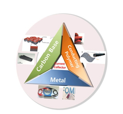
When applying a new current collector it should be in the form of a free-standing film for use in the flexible LIB. Free-standing films can be obtained either by using electrically conducting materials able to form a film by itself or by using a nonconducting flexible substrate on which electrically conducting layer is coated. Lightweight and thin, mechanically durable under deformation stress and chemically stable are critical characteristics necessary for a current collector. Carbon-based materials, conducting polymers, and flexible thin metals are potential candidates as flexible current collectors owing to their expected advantages, which will be discussed. Carbon-based materials and conducting polymers can also act as electrode materials, which show their own specific capacity. We now demonstrate representative examples of flexible current collectors (or electrodes) using these materials.
2. Carbon-based materials
Carbon-based materials such as carbon nanofibers, graphite sheets, carbon paper, carbon nanotubes (CNT), and graphene are well known electrically conducting materials. They have also been considered as materials for transparent electrodes in displays. Flexible graphite, Grafoil®, was investigated as a replacement for copper current collectors in flexible battery applications [10]. However, among these carbon-based materials used as flexible current collectors or electrodes, CNTs and graphene are the most studied materials.
2.1. Carbon Nanotube (CNT)
Carbon nanotubes can be divided into two main groups: single wall CNTs (SWCNT) and multiwall CNTs (MWCNT). The general form of CNTs used as flexible current collectors is a membrane or a paper-like film. Often electrode materials such as SnO2, Fe3O4, Si, and S are applied to the CNTs using simple loading, a deposition technique, and vacuum filtration. Uniform dispersion of nanosized active materials is one of the important criteria for successful preparation of CNTs. Ke et al. reported on a super-aligned CNT (SACNT) film as a flexible current collector, which showed an areal density as low as 0.04 mg/cm, and a thickness less than 1 μm. The sheet resistance of a single-layer SACNT was 1000 Ω/sq. Increasing the number of SACNT layers up to 20 and 100 resulted in sheet resistances of 66 Ω/sq and 11 Ω/sq, respectively [11].
By coating Si on MWCNT sheet, followed by twisting, a flexible anode for wire-type LIBs was created [12]. Cui et al. reported CNTs coated on paper where an ~2 μm thin CNT film worked as the current collector [13]. This current collector was fabricated by coating a stainless steel substrate with CNT ink containing 10% surfactant. The current collector was then removed from the substrate after coating it with the electrode materials [14]. SWCNT paper was also used as a current collector for a Si anode by a filtration method [15]. This method began with the dispersion of 30 mg of CNTs and 10 wt.% of carbon black in 1 wt.% Triton X-100 surfactant in 60 ml of distilled water. The suspension was ultrasonically agitated for 2 h and filtered through a porous poly(vinyldene fluoride) (PVDF) membrane (0.22 μm pore size). The resultant CNT mat was washed using distilled water and peeled off to form a PVDF membrane after drying. Instead of using a PVDF filter, CNT films were filtered using a Celgard 3500 separator (polypropylene) and then used as a binder-free, current collector-free anode. However, there was a severe drop of specific capacity after the 1st cycle [16].
Goyal et al. reported on CNT-Cu2O-PVDF as an electrode-separator system for flexible LIBs as shown in Fig. 2 [17]. A LiMn2O4/CNT composite was also reported as a flexible, binder-free cathode [18]. A free-standing flexible cathode was prepared by a spontaneous redox reaction of a pre-oxidized CNT network with KMnO4, which generated MnO2 wrapped around the CNTs, and was followed by a hydrothermal treatment in the presence of LiOH. Flexible sulfur-CNT cathodes fabricated with the assistance of an anodic aluminum oxide (AAO) template, free from a binder, were fabricated for use in high rate flexible Li-S batteries [19].
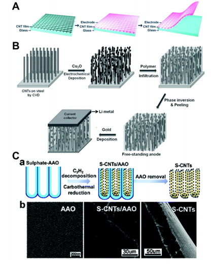
Fig. 2.
(A) Schematic of the procedure for making flexible electrodes with SACNT films functioning as lightweight and thin current collectors. The SACNT sheets are cross-stacked on a glass substrate; the electrode slurry is coated on top of the CNT film; the electrode with the CNT current collector can be then easily separated from the glass substrate after drying [11]. (B) Fabrication of schematic for Cu2O-coated CNT electrodes. The CVD-grown CNTs were coated with copper oxide using electrodeposition. After polymer infiltration, the CNTs were peeled off from the substrate to obtain free-standing electrodes on which a thin layer of gold was sputter-coated [17]. (C-a) Scheme showing the thermal decomposition of C2H2 in a sulphate-containing AAO template and the formation of S-CNTs after AAO removal. (C-b) SEM images showing the top view of a sulphate-containing AAO template, side views of S-CNTs/AAO and S-CNTs [19].
2.2. Graphene
An increasing number of intensive studies have been reported on using the use of graphene in the various fields. This also applied to the fabrication of a flexible current collector (or electrode). Gwon et al. reported graphene paper, which was fabricated from graphene nanosheets, as a flexible current collector [20]. The thickness of the graphene paper was around 2 μm and the electrical conductivity was around 80 S/cm. They reported enhanced cycle performance for a V2O5/graphene paper electrode compared to a V2O5/Al foil.
Filtration techniques are often used to prepare composites or paper with nanosized carbon materials. For example, CVD-derived graphene as a flexible paper anode has been studied. A CVD process was used to obtain graphene on expanded vermiculite, followed by acid washing. Graphene paper was fabricated by a filter method and higher reversible capacity compared to that of reduced graphene oxide (rGO) paper was reported [21]. Free-standing graphene-Si nanocomposite films can also be fabricated by the filtration of graphene oxide (GO) and nano-silicon powder, 3-80 nm in size, suspended in water. These nanocomposite films showed a discharge capacity of 708 mAh/g after 100 cycles in the form of a half-cell [22]. Similarly, free-standing graphene/SnO2 nanocomposite paper was also investigated as an alternative flexible anode [23]. As compared with CNTs, graphene-sulfur paper was investigated as a cathode for flexible LIBs by using an in situ redox reaction followed by vacuum filtration. Graphene-sulfur paper electrodes with thickness of 40-60 μm and a density of 0.4-0.6 g/cm3 were fabricated as a result.
Because the PVDF binder affects rapid capacity fading and low capacity retention of graphene-sulfur electrodes, owing to the increase of electrode polarization, binder-free cathodes showed higher cell performance [24]. Huang et al. reported a carbon nanofiber and GO-template composite solution for fabricating mesophase graphene paper. Sulfur was applied by heating the samples at 300℃ in a steel vessel for 12 h [25]. Thermally annealed graphene stacks showed severe inter-sheet aggregation that limited permeation of the electrolyte between the layers. In spite of a high Li diffusion coefficient of ~10−8 cm2/s [26], cross-plane diffusivity was low. In order to solve this problem, Zhao et al. reported the use of flexible holey graphene paper that possessed in-plane carbon vacancy defects [27]. Graphene foam, which provided a three-dimensional conductive interconnected network, worked as the current collector for a Li4Ti5O12 anode and LiFePO4 cathode, showing high rate capability [28].
3. Conducting Polymers
Electrically conducting polymers such as polypyrrole (PPy), polyaniline (PANi), and polythiophene (PTP) are of interest in fabrication of batteries. Conducting polymers can be used to prepare all-polymer-based batteries, and such batteries show a theoretical capacity ranging from 100 to 140 mAh/g [29,30]. However, the specific capacity of these conducting materials is generally low and additional active materials are required for practical consideration. The advantages of using conducting polymeric materials are that they enable free-standing and flexible film formation.
Fig. 3.
(A) Schematic representation of the nanostructured functional materials fabricated on flexible graphene paper and the interface of the composite-like structure [20]. Digital photographs of the MGP paper, exhibiting an intact paper-like morphology (B-a) and flexible property (B-b) [25].

Wang et al. have reported a flexible battery composed of a bendable paper-like polypyrrole-LiFePO4 composite cathode, flexible carbon-nanotube paper anode, and polymer electrolyte [31]. A free-standing PPy-LiFePO4 film was prepared by coating the 0.06 M pyrrole and 0.05 M tetrabutylammonium hexafluorophosphate/propylene carbonate with LiFePO4 powder onto a polished stainless steel plate, followed by the peeling off of the film after galvanostatic deposition for 1 h. The composite film exhibited a discharge capacity of 80 mAh/g, which is higher than that of PPy film (60 mAh/g) used as a comparison sample. Noerochim et al. reported a paper-like free-standing V2O5-polypyrrole cathode [32]. In this case, they used an additional steel mesh as a current collector and the polypyrrole as active material. The transparent conducting polymer, poly(3,4-ethylenedioxythiophene) (PEDOT) was also studied for fabricating a flexible anode [33]. PEDOT, with a thickness of 100 nm, was deposited on aligned CNTs on a quartz plate by chemical vapor-phase polymerization (VPP). The additional coating of a 0.5 μm thick PVDF film enabled fabrica tion of a free-standing flexible electrode. It was reported that, owing to the higher electronic conductivity of applied PEDOT, led to an increase in the discharge capacity (265 mAh/g), which is higher than using SWNT paper (173 mAh/g). Detailed information of the use of conducting polymers as electrodes for flexible batteries can be found elsewhere [34].
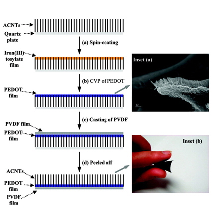
Fig. 4.
Illustration of the procedures for the preparation of a free-standing and highly conductive ACNT/PEDOT/PVDF Membrane Electrode(a) Spin-coating a thin iron (Ⅲ) tosylate film onto an ACNT modified quartz plate; (b) CVP growth of a PEDOT film on the top of ACNT forest; (c) casting of a thin PVDF film; and (d) electrode structure peeled from the quartz plate as a free-standing robust material [33].
4. Metal
Metal foils have been used in conventional LIBs as current collectors. An advantage of a metal foil is its high electrical conductivity. However, the weight of a metallic current collector is considerable and 12-μm thick current collector make up around 10% of the total weight of the battery. Also, poor adhesion owing to the smooth surface of metals is one of the disadvantages of using metallic foils. In order to utilize metallic foil as a flexible LIB current collector, the foil thickness should be thinner than that of conventional cases.
Park et al. reported use of reactive-ion etching (RIE) process to obtain honeycomb-patterned Al and Cu current collectors with a pattern width and depth of 50 μm and 10 or 5 μm, respectively. The 3D surface of the current collector enabled improved adhesion by increased surface area. A pouch cell was tested under a bending speed of 30 mm/min under 11.0 N during charge and discharge cycles at 4 C [35]. Our group has reported a thin (<1 μm) metal layer sputtered onto the porous polymeric membrane, which is generally used as a separator material. The current collector provided a rough surface, which reflects the surface morphology of the separator, and the weight of the current collector was considerably reduced owing to the small amount of metal used as the current collector. Surface resistance was lower than 1 Ω/sq, showing high electrical conductivity. When this current collector was applied as a current collector for a thin film silicon anode, it showed superior performance compared to a LIB using commercialized copper foil [36]. This concept can be extended to the new concept of sandwich current collector that exists between two different anodic materials [37]. Metallic mesh type current collectors are another approach for using metal as a flexible current collector. Unlike thin film type metal layers, the metallic mesh is a free-standing layer and the contribution of the metal to the weight of LIB can be lowered if using a thin fibrous metal. In addition, the 3D character of this material enables good electrical conductivity through the electrode, which allows for potential use as a current collector in active materials with low electrical conductivity. Stainless steel type [38] and Ni foam type meshes have also been reported for this application [39].
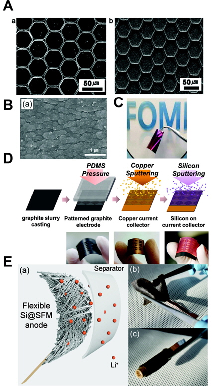
Fig. 5.
(A-a,b) Scanning electron microscopy (SEM) images (top view) of patterned Al and Cu foil [35]. (B) SEM images of the flexible current collectors based on pristine porous membrane. (C) Silicon sputtered onto the copper layer [36]. (D) Fabrication steps of graphite/Si hybrid electrode [37]. (E-a) Schematic of the flexible anode consisting of a Si coating on a nonwoven 3D stainless steel fibril mat (Si@SFM). (E-b,c) Photographs showing the flexibility of the Si@SFM anode against application of external bending and rolling stresses [38].
4. Conclusion
We have demonstrated materials for soft current collectors and the various strategies used to obtain flexible electrodes. During the last decade of research, there has been considerable progress in the field of flexible LIBs. However, certain challenges remained to be solved. One clear fact is that a light-weight, highly conductive, electrochemically stable, thin, flexible, and free-standing current collector will continue to be an important topic of investigation.


